TW4NC6012.4GhZ Color Wireless MEPG-4 Video Network Camera
Shenzhen AEE Wireless Technology Co., Ltd.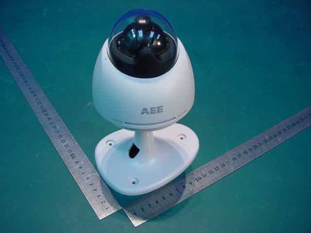
Click to zoom
Application Details
- Equipment Class
- DTS - Digital Transmission System
- Date of Grant
- Jul 13, 2006
- Application Purpose
- Original Equipment
- Date of Application
- Jul 13, 2006
- Equipment Note
- 2.4GhZ Color Wireless MEPG-4 Video Network Camera
- Frequency Range
- 2412.00000000 - 2462.00000000
- Country
- China
Documents & Files
Document Text
Text extracted from the exhibit documents filed with the FCC. Open a document above to read the original.
Users Manual
Please read this manual carefully and thoroughly before any attempt to install and operate this product and retain it for your future reference. User's Manual 2.4GHz Color Wireless MPEG-4 Video Network Camera MODEL: NC601 English R EU Environmental Protection Waste electrical products should not be disposed of with household waste. Please recycle where facilities exist. Check with your Local Authority or retailer for recycling advice. IP Finder Installation Network Parameters 29~49 INTRODUCTION1~5 Maintenance 3 Restrictions 2 Copyright 2 Warranty 2 Notice 1 Package Contents 6 Camera Feature Locations 7 6~8 PRODUCT UPnP Function 18~21 17 15~16 Proxy Server Setting 13~14 Network Camera Configuration Type 11~12 Network Camera Installation 9~10 PREPARATION9~24 Adapter 8 Approval Information (FCC/CE) 1 TABLE OF CONTENTS PC System Requirements 8 Internet Explorer Security Setting 21~23 Set the Network Camera as Virtual Server 23 Power on the Network Camera 24 NETWORK CAMERA SCREEN AND SETUP WINDOW25~51 Main Features 4~5 Network Camera Setting Interface Operating Bar Misc Setup Date & Time User Management System Identity FTP Setup E-mail Setup Motion Detection Setup UPnP Setup DDNS Setup PPPoE Setup Ethernet Setup Wireless Setup Pan/Tilt Setup Camera Setup 27~28 Firmware Upgrade Backup or Reset 48~49 47 46 45 43~44 42 41 40 39 38 35~37 34 33 32 31 30 CAMERA NETWORK ALARM TOOLS 25-26 Review images from the Network Camera 50 GLOSSARY56 TROUBLESHOOTING 55 SPECIFICATIONS 54 52~53 System Information Reboot System Wizard Support 50 51 51 50~51 Speedread your Network Camera DEFAULT SETTINGS INTRODUCTION Thank you for your interest and support in our product and purchasing this wireless home network camera. This product eel confident that you will be pleased with the quality and features of this product. works at ISM-2.4GHz frequency band, which could be legally used worldwide without permission. We f Notice This product may cause interferences with other wireless equipment that operates at 2.4GHz ISM band. Please turn off one of the equipments to eliminate the interference. Product Assurance This camera will emit electromagnetic wave, just like other wireless products. But its transmitting power is lesser than other wireless products such as mobile phones. The 2.4GHz wireless camera meets wireless frequency security standards and recommended indexes while working. These standards and indexes are certificated by academic organization and represent the cogitative research of the scientific workers who continuously explore and annotate the involved fields. So we believe that our products are safe for customers. 1 All our products meet the requirements of approval FCC or CE, and are granted the FCC or CE certification. They are authorized to bear FCC or CE mark. Approval Information After testing the product, we confirm that it complies with the provision for class C digital equipment in the 15th part in FCC regulation; and the receiver complies with the limitations for class B digital equipment in Part 15 of FCC regulation. The product generates, applies and emits radio waves. It might cause harmful interferences to wireless communication if not be installed and used following the description of the manual. The product may cause interference in residential area, and the customer should take remedies to eliminate the interference at their own costs. If the product causes any harmful interference to wireless equipment or disturbs the receiving of TV signals (it can be identified by turning on and off the product), you can solve the trouble by following methods: FCC This product complies with standards including Low Voltage Device Directive 73/23/EEC; EMC Directive 89/336/EEC and R&TTE Directive 1999/5/EC. It passed the subject tests by the authority concerned and is authorized to bear CE mark. CE This product meets the requirements specified in Part 15 of FCC Regulation. Operation rests with the following two conditions: (1) The equipment should not cause any harmful interference; (2) The equipment must receive and process any interference, including any possible interference caused by operation mistakes. (1) Readjust the product or put it in another place; (2) Extend the distance between the equipment interfered and the product; and (3) Refer to dealers or experienced radio electrician for help. Copyright This manual is furnished under license and may be used or copied only in accordance with the terms of such license. Except as permitted by such license, no part of this publication may be reproduced, stored in a retrieval system, or transmitted, in any form or any means, electronic, mechanical, recording, or otherwise, including translation to another language or format, without prior written permission of AEE Technology. Warranty AEE Technology warrants that this product will be free from defects in materials and workmanship for period of time specified. This limited warranty shall commence from the date of purchase. AEE Technology product's warranty is not transferable and is limited to the original purchaser. If the product is found to be defective then, as your sole remedy and as the manufacturer's only obligation, AEE Technology will repair or replace the product. 2 This warranty shall not apply to products that have been subjected to abuse, misuse, abnormal electrical or environmental conditions, normal wear and tear or any condition other than what can be considered normal use. Should you have problems, please consult the local dealer. The content of this manual is furnished for informational use only, is subject to change without notice, and should not be construed as a commitment by AEE Technology. AEE Technology assumes no responsibility or liability for any errors or inaccuracies that may appear in this booklet. All other product names, trademarks and registered trademarks in this document are the properties of their respective holders. 1. DO NOT use this product to violate one's privacy. Moni…
Text truncated - open the document above for the full version.
Cover Letter(s)
American Telecommunications Certification Body Inc. 6731 Whittier Ave, McLean, VA 22101 July 10, 2006 RE: FCC ID: TW4NC601_ATCB003726 Attention: Xie ShuPing I have a few comments on this Application. Please note that further comments may arise in response to answers provided to the questions below. 1. Please note that the 731 says the power out of the device is 0.2mW. Please note that the measurement results for the conducted power using the diode detector method shows the output power to be 0.25mW. Please correct the 731 to show the same measure out put power as the report. 2. Please note that PPSD of a 15.247 device is to be measured using a sweep time of (Span in MHz/3kHz). In the case of the data shown on page 25 of the report where the span is 2MHz this would be a sweep time of 2MHz/3kHz or 666seconds. Please note that the sweep time shown is only 1 second. Please redo the test using the proper sweep time as stated in the DTS test procedure provided by the FCC for DTS testing. Alternately, please show how the test method used meets the requirements of PPSD test method 2. 3. Please note that the restricted band at 2483.5MHz must meet a 54dBuV/m average and a 74dBuV/m peak emissions limitation. Please note that the test report page 27 refers to page 26 as the band edge plot and delta marker. Please note that pages 28 and 29 are the band edge plots. Please also note that the delta is not 47.2dBc for channel 11 as stated on page 27 but appears to be only 34.3dBc. Please clarify the actual page references and the actual dBc for the calculations done on page 27 of the report. 4. Please note that while it may be obvious that the MPE of the device is compliant, as this is a DTS 15.247 certification, please provide the MPE report for the device. Dennis Ward mailto:[email protected] The items indicated above must be submitted before processing can continue on the above referenced application. Failure to provide the requested information may result in application termination. Correspondence should be considered part of the permanent submission and may be viewed from the Internet after a Grant of Equipment Authorization is issued. Please do not respond to this correspondence using the email reply button. In order for your response to be processed expeditiously, you must submit your documents through the AmericanTCB.com website. Also, please note that partial responses increase processing time and should not be submitted. Any questions about the content of this correspondence should be directed to the sender.
External Photos
WT68000883 1 Photo 1 Appearance of EUT Photo 2 Appearance of EUT
ID Label/Location Info
Label 40mm The Label must not be a stick-on paper label. The Label on these products must be permanently affixed to the product and readily visible at the time of purchase and must last the expected lifetime of the equipment not be readily detachable. This device complies with Part 15 o the FCC Rules. Operation is subject to the following two conditions: (1) this device may not cause harmful interference, and (2) this device must accept any interference received, including interference that may cause undesired operation. The above FCC statement is list in user manual. Proposed Label Location on EUT FCC ID: TW4NC601 NC601 FCC ID: TW4NC601 1588 15mm Label
Internal Photos
1 Photo 1 Inside of EUT Photo 2 Inside of EUT 2 Photo 3 Inside of EUT Photo 4 Inside of EUT
RF Exposure Info
S= power density P= power input to the antenna G= power gain of the antenna in the direction of 2 interest relative to an isotropic radiator R= distance to the center of radiation of the antenna Choose Occupational/Controlled General Population/Uncontrolled Tx Frequency: 2400.00 (MHz) Maximum Peak Power at Antenna Input Terminal: -6.000 (dBm) Antenna gain : 3.00 (dBi) S=1.0000 (mW/cm^2) P=0.2512 (mW) G=1.9953 (numeric) R =0.1997(cm) S (mw/cm^2) at specific distance in cm Enter distance desired in cm 9.96E-0520 OET Bulletin 65, Edition 97-01 Prediction of MPE Limit Equation from page 18 2 4R PG S π = 4 R PG S π =
Test Report
Report No.:WT68001138 Page 1/33 EMC TEST REPORT For 2.4G Color Wireless MEPG-4 Video Network Camera Model Number: NC601 FCC ID: TW4NC601 Report Number : WT068001138 Test Laboratory : Shenzhen Academy of Metrology and Quality Inspection EMC Laboratory Guangdong EMC Compliance Test Center Site Location : Bldg. of Metrology &Quality Inspection, Longzhu Road, Shenzhen, Guangdong, China Tel : 0086-755-26941637, 26941529, 26941531 Fax : 0086-755-26941545 Email : [email protected] Report No.: WT068001138 Page 2/33 TABLE OF CONTENTS TEST REPORT DECLARATION ........................................................................................................4 1. TEST RESULTS SUMMARY ...................................................................................................5 2. GENERAL INFORMATION ....................................................................................................6 2.1. Report information ............................................................................................................6 2.2. Laboratory Accreditation and Relationship to Customer .................................................6 2.3. Measurement Uncertainty .................................................................................................7 3. PRODUCT DESCRIPTION ......................................................................................................7 3.1. EUT Description ...............................................................................................................7 3.2. Related Submittal(s) / Grant (s) ........................................................................................8 3.3. Block Diagram of EUT Configuration..............................................................................8 3.4. Operating Condition of EUT ............................................................................................8 3.5. Special Accessories...........................................................................................................8 3.6. Equipment Modifications..................................................................................................8 3.7. Support Equipment List ....................................................................................................8 3.8. Test Conditions .................................................................................................................8 4. TEST EQUIPMENT USED .......................................................................................................9 5. CONDUCTED DISTURBANCE TEST ..................................................................................10 5.1. Test Standard and Limit ..................................................................................................10 5.2. Test Procedure ................................................................................................................10 5.3. Test Arrangement............................................................................................................10 5.4. Test Data .........................................................................................................................10 6. RADIATED DISTURBANCE TEST ......................................................................................15 6.1. Test Standard and Limit ..................................................................................................15 6.2. Test Procedure ................................................................................................................15 6.3. Test Arrangement............................................................................................................15 6.4. Test Data .........................................................................................................................16 7. 6DB BANDWIDTH MEASUREMENT..................................................................................20 7.1. LIMITS OF 6dB BANDWIDTH MEASUREMENT.....................................................20 7.2. TEST PROCEDURE ......................................................................................................20 7.3. TEST SETUP ..................................................................................................................20 7.4. EUT OPERATING CONDITIONS ................................................................................20 7.5. Test Data .........................................................................................................................20 8. MAXIMUM PEAK OUTPUT POWER .................................................................................24 8.1. LIMITS OF MAXIMUM PEAK OUTPUT POWER MEASUREMENT .....................24 8.2. TEST PROCEDURES ....................................................................................................24 8.3. TEST SETUP ..................................................................................................................24 8.4. EUT OPERATING CONDITIONS ................................................................................24 8.5. Test Data .........................................................................................................................24 9. POWER SPECTRAL DENSITY MEASUREMENT............................................................25 9.1. LIMITS OF POWER SPECTRAL DENSITY MEASUREMENT................................25 9.2. TEST PROCEDURE ......................................................................................................25 9.3. 4.5.5 TEST SETUP .........................................................................................................25 9.4. 4.5.6 EUT OPERATING CONDITION .........................................................................25 9.5. Test Data .........................................................................................................................25 Report No.: WT0680…
Text truncated - open the document above for the full version.
Test Setup Photos
1 Photo 1 Conducted Emission Test Photo 2 Conducted Emission Test 2 Photo 3 Radiated Emission Test Photo 4 Radiated Emission Test
Contact Information
Applicant
James Xiao
Test Firm
Shenzhen Academy of Metrology & Quality InspectionPeter Lin
Technical Specifications
| # | Rule Parts | Frequency Range | Power Output |
|---|---|---|---|
| 1 | 15C | 2.41 GHz - 2.46 GHz | 250.00 µW |
Other Applications from Shenzhen AEE Wireless Technology Co., Ltd.
TW4870VL
Apr 06, 20082.4G Wireless Transceiver
Equipment Class
DXX - Part 15 Low Power Communication Device Transmitter
TW4-AT202-900M
Apr 06, 2008Wireless IP Camera
Equipment Class
DXX - Part 15 Low Power Communication Device Transmitter
TW4CT002
Sep 04, 20072.4G Wireless camera
Equipment Class
DXX - Part 15 Low Power Communication Device Transmitter
TW4CT011
Jun 18, 20072.4 GHz Wireless Camera
Equipment Class
DXX - Part 15 Low Power Communication Device Transmitter
TW4BT501
Dec 20, 20062.4 Ghz Wireless Camera
Equipment Class
DXX - Part 15 Low Power Communication Device Transmitter