U4A-ADA1028W2Wireless Interface Device
ASSA ABLOY Inc.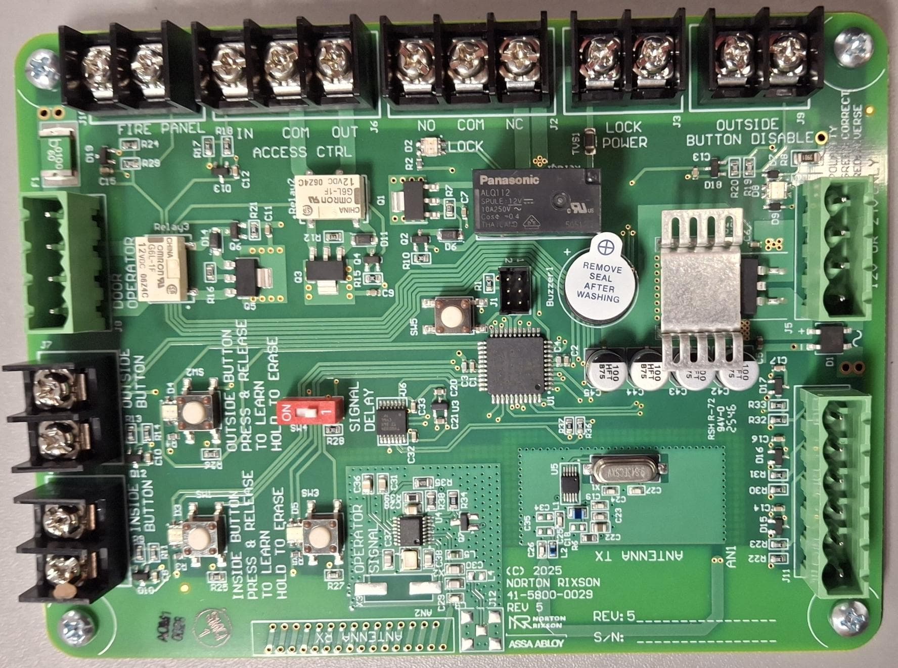
Click to zoom
Application Details
- Equipment Class
- DSR - Part 15 Remote Control/Security Device Transceiver
- Date of Grant
- Aug 07, 2026
- Application Purpose
- Original Equipment
- Equipment Note
- Wireless Interface Device
- Frequency Range
- 315.00000000 - 315.00000000
- Company
- ASSA ABLOY Inc.
- Country
- United States
Documents & Files
Document Text
Text extracted from the exhibit documents filed with the FCC. Open a document above to read the original.
Users Manual
700703 REV K 07/26 Wireless Interface Module (WIM) Installation and Operation Instructions Copyright © 2017, 202 6, A SSA ABLOY Accessories and Door Controls Group, Inc. All rights reserved. Reproduction in whole or in part without the express written permission of ASSA ABLOY Accessories and Door Controls Group, Inc. is prohibited. 1 of 16 Wireless Interface Module (WIM) Installation and Operating Instructions To obtain the latest manual and template revisions or to view installation and programming videos go to www.NortonRixson.com. For technical support call 877-974-2255 ext. 2. CAUTION Changes or modifications not expressly approved by the party responsible for compliance could void the user's authority to operate this device. INSIDE BUTTON INSIDE BUTTON PRESS & RELEASE TO LEARN HOLD TO ERASE OUTSIDE BUTTON DOOR OPERATOR FIRE PANEL IN COM OUT ACCESS CTR OUTSIDE BUTT ON DISABLE LOCK POWER NO COM NC LOCK OUTSIDE BUTTON PRESS & RELEASE TO LEARN HOLD TO ERASE OPERATOR SIGNAL SIGNAL DELAY POWER IN 12 OR 24V + CH S 700703 REV K 07/26 Wireless Interface Module (WIM) Installation and Operation Instructions Copyright © 2017, 202 6, A SSA ABLOY Accessories and Door Controls Group, Inc. All rights reserved. Reproduction in whole or in part without the express written permission of ASSA ABLOY Accessories and Door Controls Group, Inc. is prohibited. 2 of 16 Prerequisites 2 1. A 5800 Series door operator installed according to 5800 Series Low Energy Operator Installation and Operating Instructions p/n 700002 with optional Hardwire Kit p/n 1015 or 24VDC (500ma minimum) power supply by others. 2. 12 or 24V AC or DC to power the WIM. 3. 24VDC is REQUIRED if the 5800 door operator will be powered thorough the WIM with the supplied cable. 4. Protective barrier (caution/warning tape) has been set up to prevent unauthorized access to work area. 5. The door has been secured to prevent unexpected opening or closing during installation. Discussion This manual provides system description, installation instructions, operating instructions, and troubleshooting recommendations for the Wireless Interface Module (referred to as the WIM). The WIM allows the door operator to interface with the wired or wireless push buttons, wireless remote, an electric lock, fire panel, access control, and an outside push button disable contact. Applicability This manual is applicable to the 5800 Series Wireless Interface Module. Purpose 1 Precautions 3 1. This product is intended for interior use only. 2. An operating door creates pinch hazards. Be careful making operating adjustments while the door is moving. 3. The transformer wiring must not be concealed behind walls or routed through doorways, window openings, walls, ceilings, or floors. Also, this wiring must be secured to prevent it from becoming entrapped in the moving parts of the operator or door. 700703 REV K 07/26 Wireless Interface Module (WIM) Installation and Operation Instructions Copyright © 2017, 202 6, A SSA ABLOY Accessories and Door Controls Group, Inc. All rights reserved. Reproduction in whole or in part without the express written permission of ASSA ABLOY Accessories and Door Controls Group, Inc. is prohibited. 3 of 16 System Description 4 General The WIM allows the door operator to interface with: • Wireless (RF) push buttons or • Wired push buttons • Wireless (RF) hand held transmitter • Electric Lock • Access Control • Fire Panel • Switch to disable outside push button 1. Push Buttons: A wired and wireless input is provided for an INSIDE and an OUTSIDE push button. An optional handheld transmitter (p/n ADA1031) may be programmed to either the INSIDE or OUTSIDE activation connection. 2. Operator Connection: A cable assembly (p/n ADA1015C) is provided to plug in the door operator into the WIM module. 3. Access Control: Contacts are provided to interface the WIM with access control. 4. Lock Interface: Contacts are provided to control an electrical lock. 5. Lock Power: Contacts are provided to power an electric lock. 6. Outside Push Button Disable: A contact is provided to disable any input from an outside push button. 7. Power Input: A power input connector is provided to power the WIM by a 12 or 24V AC/DC* power supply or using the optional hardwire kit (p/n ADA1015P). 8. Signal Delay: A switch is provided to enable a 1 second delay before sending an activate signal to the door operator. *If the Door Operator will be powered using the supplied cable assembly (p/n ADA1015C) the WIM must be powered by a 24VDC 750mA minimum power supply. Inputs & Outpus 5 700703 REV K 07/26 Wireless Interface Module (WIM) Installation and Operation Instructions Copyright © 2017, 202 6, A SSA ABLOY Accessories and Door Controls Group, Inc. All rights reserved. Reproduction in whole or in part without the express written permission of ASSA ABLOY Accessories and Door Controls Group, Inc. is prohibited. 4 of 16 6 Mount and Apply Power to the WIM 1. Mount the WIM enclosure in a remote location as desired. NOTE: The WIM may be powered by 12 or 24 Volts AC or DC current. If the door operator will be powered directly from the WIM, a 24VDC 750ma (minimum) power supply is required. 2. Provide power to the WIM. (Refer to Figure 1) a. If the Optional hardwire kit (p/n ADA1015P) is used to power the WIM and door operator, plug the provided GREEN connector into the power port as shown. b. If Power supply is by others, connect the power supply using the provided GREEN connector. If a DC power supply is used connect the ground to the terminal marked “-“ and the positive to the terminal marked “+”. c. If the operator will be powered through the WIM,use the supplied Operator Wire Harness (p/n ADA1015C) to power the Operator. When power is properly applied to the operator, the LED on the bottom of the battery pack will light steady GREEN. d. When the WIM is properly wired with power applied LED D8 near the power connector will light GREEN. Figure 1 INSIDE BUTTON INSIDE BUTTON PRESS & RELEASE TO …
Text truncated - open the document above for the full version.
Attestation Statements
Public Date: June 22, 2026 Attention: Application Examiner RE: Certification designating a U.S. agent for service of process pursuant to 47 CFR part 2.911(d)(7) of the FCC rules To Whom It My Concern: This letter is to certify that ASSA ABLOY Inc. (“Applicant”) accepts responsibilities to act as its own agent pursuant to 47 CFR part 2.911(d)(7) of the FCC rules for service of process. I consent to the obligation to accept service of process on behalf of the applicant in regard to the FDD ID designed below. I HEREBY CERTIFY THAT I am authorized to make the representations above on behalf of the Applicant. I further acknowledge the requirement to maintain an agent extends for no less than one year after the termination of all marketing and importation or the conclusion of and commission- related proceeding involving the equipment and agree to immediately notify the FCC and Intertek if there is any change in the status identified above. Applicant Company Name: ASSA ABLOY Inc. Contact Name: James W Forte Address: 110 Sargent Drive, New Haven, CT 06511 Telephone No.: 203-821-5788 Email: [email protected] FCC ID: U4A-ADA1028W2 Applicant FRN: 0016550824 Jim Forte Regulatory Compliance Project Manager
Attestation Statements
Public Date: June 22, 2026 Attention: Application Examiner RE: Covered List, located at https://www.fcc.gov/supplychain/coveredlist and 47CFR parts 2.903 and 2.911(d)(5)(ii) of the FCC rules Applicant: ASSA ABLOY Inc FCC ID: U4A-ADA1028W2 To Whom It My Concern: ASSA ABLOY Inc. (“Applicant”) certifies that the equipment for which authorization is sought is not “covered” equipment prohibited from receiving an equipment authorization pursuant to 47 CFR part 2.903 of the FCC rules and does not originate directly or indirectly from any company named on the covered list located in the link above or any subsidiary or affiliate thereof. Applicant further certifies that, as of the date of the filing of the application, the Applicant is not identified on the Covered List as an entity producing “covered” equipment and is not a subsidiary or affiliate of any such entity pursuant of 47 CFR part 1.50002 and required by 47 CFR part 2.911(d)(5)(ii) of the FCC rules. Applicant further certifies that no Cybersecurity or anti-virus software produced or provided by Kaspersky Lab, Inc. or any of its successors and assignees, including equipment with integrated Kaspersky Lab, inc. (or any of its successors and assignees) cybersecurity or anti-virus software is installed in the equipment being certified. I HEREBY CERTIFY THAT I am authorized to make the representations above on behalf of the Applicant and agree to immediately notify Intertek if there is any change to the status identified above. Jim Forte Regulatory Compliance Project Manager
Cover Letter(s)
Public Date: June 22, 2026 Attention: Application Examiner RE: Request for Confidentiality Applicant: ASSA ABLOY Inc. FCC ID: U4A-ADA1028W2 To Whom It My Concern: Permanent Confidentiality Request is hereby submitted by ASSA ABLOY Inc. to withhold permanently from public review certain portions of the application for equipment certification for the referenced FCC identifiers. This request for confidentiality is made pursuant to 47 CFR 0.457(d) and 0.459 of the FCC Rules. In particular, the following sections of the application are to be kept permanently confidential: • Schematics • Detailed Block Diagrams • Detailed Operational / Functional Description Rationale for request for confidentiality: ASSA ABLOY Inc. has invested considerable time and materials in research and development to produce the referenced product. Disclosure of the permanently confidential portions of this application to competitors would not only give them significant competitive advantages in developing similar products, but would also disclose successful implementation of unpublished, leading edge technology developed by us. If you have any questions or need further information, please contact the undersigned. Sincerely, Jim Forte Regulatory Compliance Project Manager
External Photos
Public Date: June 24, 2026 RE: Board photos Applicant: ASSA ABLOY Inc FCC ID: U4A-ADA1028W2 IC: 6982A-ADA1028W2 The board PN 41-5800-0029, also referred to as 5800WIM, under FCC ID U4A-ADA1028W2 and IC 6982A-ADA1028W2 is not shipped in an enclosure. Below are pictures of the front of the board with the antenna called out and the back of the board with the label placement included: Figure 1 Front on board Antenna Public Figure 2 Back of board and label placement
ID Label/Location Info
Label - 5800 WIM FCC 80-9310-0592-020 Rev 1 Rev. Eng. Description 1 tommcn ECN 26-0106 New Label Copyright © 2026, ASSA ABLOY Accessories and Door Controls Group, Inc. All rights reserved. Reproduction in whole or in part without the express written permission of ASSA ABLOY Accessories and Door Controls Group, Inc. is prohibited. 80-9310-0592-020 05-261 www.nortonrixson.com 1-877-974-2255 1.10+/-.10” NOTES: 1. MATERIAL: WHITE POLYESTER W/ PERMANENT ADHESIVE. 2. PRINTED BLACK 3. POSITIONING OF TEXT IS FOR REFERENCE ONLY. 3.10+/-.10” FCC ID: U4A-ADA1028W2 IC: 6982A-ADA1028W2 HVIN: ADA1028W2 MODEL: ADA1028W This device complies with Part 15 of the FCC Rules. Operation is subject to the following two conditions: (1) this device may not cause harmful interference, and (2) this device must accept any interference received, including interference that may cause undesired operation. 80-9310-0592-020 Rev 1 REVDATE TEMPLATE NUMBER
ID Label/Location Info
© ASSA ABLOY. All rights reserved Use the Picture Library to insert a picture into the background. 1 Front of board Back of board with label placement ADA1028W2 P/N: 41-5800-0029-999 Side profile of board
Internal Photos
Public Date: July 16, 2026 RE: Board photos Applicant: ASSA ABLOY Inc FCC ID: U4AADA1028W2 The board PN 41-5800-0029, also referred to as 5800WIM, under U4AADA1028W2 is not shipped in an enclosure. Below are pictures of the front of the board with the antenna called out, back of the board, side and top edges of board, and the back of the board with the label placement included: Figure 1 Front on board Antenna Public Figure 2 Back of board Figure 3 Side of board Figure 4 Top edge of board Public Figure 5 Back of board showing label location
RF Exposure Info
DOCUMENT CONTROL NUMBER Non-Specific Radio Report Shell Rev. December 2017 © 2017 INTERTEK ASSA ABLOY INC. SAR EXEMPTION REPORT SCOPE OF WORK SAR EXEMPTION – ADA1028W2 REPORT NUMBER 106579497ATL-002A ISSUE DATE REVISION DATE 05 August 2026 N/A PAGES 8 SAR EXEMPTION REPORT Report Number: 106579497ATL-002A Project Number: G106579497 Issue Date: 05 August 2026 PMN: ADA1028W Model/HVIN: ADA1028W2 FCC ID: U4A-ADA1028W2 IC: 6982A-ADA1028W2 Standards: FCC Title 47 CFR Part 2.1093 RSS-102, Issue 6 Test Location Client Intertek 1950 Evergreen Blvd., Suite 100 Duluth, GA 30096 USA FCC Designation: US1046 CAB Designator: US0128 ASSA ABLOY Inc. 110 Sargent Drive PO Box 9725 New Haven, Connecticut USA Report prepared by Report reviewed by Jeremy Pickens / Senior Staff Engineer Uri Spector / Sr. EMC Staff Engineer This report is for the exclusive use of Intertek's Client and is provided pursuant to the agreement between Intertek and its Client. Intertek's responsibility and liability are limited to the terms and conditions of the agreement. Intertek assumes no liability to any party, other than to the Client in accordance with the agreement, for any loss, expense or damage occasioned by the use of this report. Only the Client is authorized to permit copying or distribution of this report and then only in its entirety. Any use of the Intertek name or one of its marks for the sale or advertisement of the tested material, product or service must first be approved in writing by Intertek. The observations and test results in this report are relevant only to the sample tested. This report by itself does not imply that the material, product, or service is or has ever been under an Intertek certification program. Intertek Report Number: 106579497ATL-002A Issued: 05 August 2026 Non-Specific Radio Report Shell Rev. January 2025 Page 3 of 8 ASSA Abloy Inc / ADA1028W2 Table of Contents 1 Introduction and Conclusion .............................................................................................................. 4 2 Evaluation Summary ........................................................................................................................... 4 3 Client Information ................................................................................................................................ 5 4 Description of Equipment Under Test ............................................................................................... 5 5 Maximum Permissible Exposure Criteria .......................................................................................... 6 6 ISED Routine Evaluation Exemption Criteria .................................................................................... 7 7 Revision History ................................................................................................................................... 8 Intertek Report Number: 106579497ATL-002A Issued: 05 August 2026 Non-Specific Radio Report Shell Rev. January 2025 Page 4 of 8 ASSA Abloy Inc / ADA1028W2 1 Introduction and Conclusion RF Exposure measurements were performed on the product constructed as described in Section 4. Based on the results of our investigation, we have concluded the product under evaluation complies with the standard(s) indicated. The results obtained in this test report pertain only to the item(s) evaluated. Intertek does not make any claims of compliance for samples or variants which were not evaluated. 2 Evaluation Summary Section Test full name Result 5 RF Exposure (FCC Title 47 CFR Part 2.1093) Compliant 6 RF Exposure (RSS-102 Issue 6) Compliant Intertek Report Number: 106579497ATL-002A Issued: 05 August 2026 Non-Specific Radio Report Shell Rev. January 2025 Page 5 of 8 ASSA Abloy Inc / ADA1028W2 3 Client Information This evaluation was performed at the request of Client: ASSA ABLOY Inc. 110 Sargent Drive PO Box 9725 New Haven, Connecticut USA Contact: Tommy McNally Email: [email protected] 4 Description of Equipment Under Test Manufacturer: ASSA ABLOY Inc. 110 Sargent Drive PO Box 9725 New Haven, Connecticut USA Equipment Under Test Description Manufacturer Model Number Serial Number Wireless Interface Module ASSA ABLOY Inc ADA1028W2 Not Labeled Receive Date: 19 May 2026 Received Condition: Good Type: Production Description of Equipment Under Test (provided by client) The DUT was a wireless controller board for an automated door system. Certification Purpose Original Certification Radio/Receiver Characteristics Frequency Range 315MHz Field Strength (3m): 73.46dBμV/m (measured) Maximum Conducted Power: 10dBm (10mW) Note: (From chipset data sheet - Intertek takes no responsibility for the accuracy of this information.) Antenna Type Printed Circuit Board Intertek Report Number: 106579497ATL-002A Issued: 05 August 2026 Non-Specific Radio Report Shell Rev. January 2025 Page 6 of 8 ASSA Abloy Inc / ADA1028W2 5 Maximum Permissible Exposure Criteria Per 447498 D01 General RF Exposure Guidance v06 Section 4.3.1, for frequencies between 100 MHz and 6GHz, the following may be considered for SAR test exclusion (also illustrated in Appendix A): 1) For test separation distances ≤ 50 mm, the 1-g and 10-g SAR test exclusion thresholds are determined by the following: where [(max. power of channel, including tune-up tolerance, mW) / (min. test separation distance, mm)]*[√f(GHz)] ≤ 3.0 for 1-g SAR, and ≤ 7.5 for 10-g extremity SAR,30 • f(GHz) is the RF channel transmit frequency in GHz • Power and distance are rounded to the nearest mW and mm before calculation 5.1 Calculations 10mW/5mm* √(0.315GHz) = 1.12 which is less than 3 Note: For antenna gains less than 0dBi, 0 is used for the power calculation 5.2 Results The maximum output power is less than the SAR exclusion limits for any separation distance, and therefore, no RF exposure evaluation is required. Intertek Report Number: 106579497ATL-002A Issued: 05 August 2026 Non-Specific Radio Report Shell Rev. January 2025 Page 7 of 8 A…
Text truncated - open the document above for the full version.
Test Report
Date: June 5, 2026 RE: Antenna construction report Applicant: ASSA ABLOY Inc FCC ID: U4A-ADA1028W2 1.0 TX Antenna Design The antenna for PN 41-5800-0029, also referred to as “5800 WIM”, was designed based on Micrel/Microchip’s design notes to go with the MICRF112 integrated circuit. These documents are being sent with this document for reference: a.TX112PCB_Layout.doc b.TX112_ANT_DIM_TOP.pdf c.TX112_ANT_DIM_BOT.pdf These describe the layout of the antenna, and where the ground plane should stop. There is an example layout of the RF IC and associated components, which was used as a reference, but some changes were made, since the components used and the components in the example were not one-to-one. Figure 1: Excerpt from TX112PCB_Layout.doc 2.0 41-5800-0029 TX Antenna Details The PCBA for the 41-5800-0029 is a four-layer PCBA. However, all traces and planes, except the antenna traces, stop before the antenna region, as specified by the MICRF112 antenna recommendations, as can be seen in Figure 2. Also visible in Figure 2 is the actual dimensions of the 41-5800-0029 board. Figure 2: 41-5800-0029 Layout, Viewed in Altium Figure 3 shows the layer stack-up for the PCB. In the antenna region, the Ground and Power layers have been removed. This means the total dielectric thickness between the top and bottom traces is approximately 57.8mils +/-13%. Both the top and bottom antenna traces are 1oz copper. Figure 3: 41-5800-0029 Layer Stack-up The upward protrusion of the planes to the left of the antenna starts 115mils (2.92mm) away and is outside the current loop of the antenna. The dimensions of the plane, nearest to the antenna, can be seen in Figure 4. Figure 4: Dimensions of Plane Protrusion, Near Antenna Finally, exact dimensions of the antenna were used from the dimensions in the referenced documents TX112_ANT_DIM_TOP.pdf and TX112_ANT_DIM_BOT.pdf (included with this package and referenced in Figure 5 and Figure 6). The layout of the RF circuit and board dimensions varies. Figure 5: Antenna Layout – Top Layer Figure 6: Antenna Layout – Bottom Layer
Test Report
DOCUMENT CONTROL NUMBER Non-Specific Radio Report Shell Rev. January 2025 © 2025 INTERTEK ASSA ABLOY INC. TEST REPORT SCOPE OF WORK RADIO TESTING – ADA1028W2 REPORT NUMBER 106579497ATL-001 ISSUE DATE REVISED DATE 04 June 2026 15 July 2026 PAGES 27 RADIO TEST REPORT Report Number: 106579497ATL-001 Project Number: G106579497 Revised Date: 15 July 2026 PMN: ADA1028W Model/HVIN: ADA1028W2 FCC ID: U4A-ADA1028W2 IC: 6982A-ADA1028W2 Standards: 47 CFR Part 15 Subpart C, 15.231 RSS-210, Issue 11 ANSI C63.10-2020+Cor. 1-2023+C63.10a-2024 + Errata to C63.10a-2024 Test Location Client Intertek 1950 Evergreen Blvd., Suite 100 Duluth, GA 30096 USA FCC Designation: US1046 CAB Designator: US0128 ASSA ABLOY Inc. 110 Sargent Drive PO Box 9725 New Haven, Connecticut USA Report prepared by Report reviewed by Jeremy Pickens / Senior Staff Engineer Uri Spector / Sr. EMC Staff Engineer This report is for the exclusive use of Intertek's Client and is provided pursuant to the agreement between Intertek and its Client. Intertek's responsibility and liability are limited to the terms and conditions of the agreement. Intertek assumes no liability to any party, other than to the Client in accordance with the agreement, for any loss, expense or damage occasioned by the use of this report. Only the Client is authorized to permit copying or distribution of this report and then only in its entirety. Any use of the Intertek name or one of its marks for the sale or advertisement of the tested material, product or service must first be approved in writing by Intertek. The observations and test results in this report are relevant only to the sample tested. This report by itself does not imply that the material, product, or service is or has ever been under an Intertek certification program. Intertek Report Number: 106579497ATL-001 Revised: 15 July 2026 Non-Specific Radio Report Shell Rev. January 2025 Page 3 of 27 ASSA Abloy Inc / ADA1028W2 Table of Contents 1 Introduction and Conclusion .............................................................................................................. 4 2 Test Summary ...................................................................................................................................... 4 3 Client Information ................................................................................................................................ 5 4 Description of Equipment Under Test and Variant Models ............................................................. 5 5 Bandwidth ............................................................................................................................................. 7 6 Field Strength of the Fundamental / Radiated Spurious Emissions .............................................. 9 7 Deactivation Time .............................................................................................................................. 18 8 AC Mains Conducted Emissions ...................................................................................................... 20 9 Measurement Uncertainty ................................................................................................................. 22 10 Revision History ............................................................................................................................. 23 APPENDIX: DUTY-CYCLE CORRECTION ............................................................................................... 24 Intertek Report Number: 106579497ATL-001 Revised: 15 July 2026 Non-Specific Radio Report Shell Rev. January 2025 Page 4 of 27 ASSA Abloy Inc / ADA1028W2 1 Introduction and Conclusion The tests indicated in Section 2 were performed on the product constructed as described in Section 4. The remaining test sections are the verbatim text from the actual data sheets used during the investigation. These test sections include the test name, the specified test Method, a list of the actual Test Equipment Used, documentation Photos, Results and raw Data. No additions, deviations, or exclusions have been made from the standard(s) unless specifically noted. Based on the results of our investigation, we have concluded the product tested complies with the requirements of the standard(s) indicated. The results obtained in this test report pertain only to the item(s) tested. Intertek does not make any claims of compliance for samples or variants which were not tested. 2 Test Summary Section Test Description Test Specification Result FCC ISED 5 Bandwidth 15.215(c) RSS-GEN S6.7 Compliant 6 Field Strength / Spurious Emissions 15.231(b) 15.209 RSS-210 A.1.4 RSS-GEN S8.9 Compliant 7 AC Mains Conducted Emissions 15.207 RSS-GEN S8.8 Compliant 7 Deactivation Time 15.231(a)(1) RSS-210 A.1.2(a) Compliant NA Antenna Requirement 15.203 RSS-GEN S6.8 Compliant 1 1) The antenna is an integrated PCB antenna which is not removable by the end user. Intertek Report Number: 106579497ATL-001 Revised: 15 July 2026 Non-Specific Radio Report Shell Rev. January 2025 Page 5 of 27 ASSA Abloy Inc / ADA1028W2 3 Client Information This evaluation was performed at the request of: Client: ASSA ABLOY Inc. 110 Sargent Drive PO Box 9725 New Haven, Connecticut USA Contact: Tommy McNally Email: [email protected] 4 Description of Equipment Under Test and Variant Models Manufacturer: ASSA ABLOY Inc. 110 Sargent Drive PO Box 9725 New Haven, Connecticut USA Equipment Under Test Description Manufacturer Model Number Serial Number Wireless Interface Module ASSA ABLOY Inc ADA1028W2 Not Labeled Receive Date: 19 May 2026 Received Condition: Good Type: Production Description of Equipment Under Test (provided by client) The DUT was a wireless controller board for an automated door system. Certification Purpose Original Certification Radio/Receiver Characteristics Frequency Range 315MHz Field Strength (3m): 73.46dBμV/m (measured) Antenna Type Printed Circuit Board Software No. Description of EUT Software 1…
Text truncated - open the document above for the full version.
Test Setup Photos
ASSA ABLOY, Inc. Test Setup Photographs FCC ID: U4A-ADA1028W2 IC: 6982A-ADA1028W2 Radiated Spurious Emissions 9kHz-30MHz Radiated Spurious Emissions 9kHz-30MHz Radiated Spurious Emissions 9kHz-30MHz Radiated Spurious Emissions 30MHz-1GHz Radiated Spurious Emissions 30MHz-1GHz Radiated Spurious Emissions 1GHz-10GHz Radiated Spurious Emissions 1GHz-10GHz AC Conducted Emissions AC Conducted Emissions
Contact Information
Applicant
James Forte(Senior Product Compliance Engineer)
[email protected]Fax: 2034985600
Technical Contact
ASSA ABLOY Accessories and Door Controls Group, InJames Forte
3000 Highway 74 East · Monroe, North Carolina, 28112 · United States
Test Firm
Intertek Testing Services NA Inc.Jeff Hiday
Technical Specifications
| # | Rule Parts | Frequency Range | Power Output |
|---|---|---|---|
| 1 | 15.231 | 315 MHz - 315 MHz | - |
Other Applications from ASSA ABLOY Inc.
U4A5800ADAEZ2
Feb 20, 2026Wireless Interface Device
Equipment Class
DSR - Part 15 Remote Control/Security Device Transceiver
U4A-SCYMCA1K
Jul 28, 2024Aperio V3 IN100 Keypad Variant RF Module
Equipment Class
DXX - Part 15 Low Power Communication Device Transmitter
U4A-CEX100
Jun 05, 2023Access Control Lock
Equipment Class
DXX - Part 15 Low Power Communication Device Transmitter
U4A-YRHCPMT1FM
Mar 27, 2023Wireless Module to add BLE or Thread capabilities to Smart Door Locks
Equipment Class
DTS - Digital Transmission System
U4A-HCPZB231LFM
May 02, 2021Wireless Module for Door Lock
Equipment Class
DTS - Digital Transmission System