U4A-CEX100Access Control Lock
ASSA ABLOY Inc.
Click to zoom
Application Details
- Equipment Class
- DXX - Part 15 Low Power Communication Device Transmitter
- Date of Grant
- Jun 05, 2023
- Application Purpose
- Original Equipment
- Date of Application
- May 25, 2023
- Equipment Note
- Access Control Lock
- Frequency Range
- 13.56000000 - 13.56000000
- Company
- ASSA ABLOY Inc.
- Country
- United States
Documents & Files
Document Text
Text extracted from the exhibit documents filed with the FCC. Open a document above to read the original.
Users Manual
80-9000-0005 10/22 Part of ASSA ABLOY Copyright © 2022, ASSA ABLOY Access and Egress Hardware Group, Inc. All rights reserved. Reproduction in whole or in part without the express written permission of ASSA ABLOY Access and Egress Hardware Group, Inc. is prohibited. Patent pending and/or patent www.assaabloydss.com/patents. Follow the steps in the lock installation instructions to Set Up the Exterior Escutcheon. Make sure the blue plastic ‘UP’ indicator piece is pointing up after you rotate the cardboard tool. Next insert the lever lock into the shank of the exterior escutcheon, making sure the triangle shaped boss of the lever lock is facing up as pictured below. Now insert the outside lever onto the shank until it snaps into position. Pull on the lever to ensure it is secure. No Key Override Option (CEx102) Installation: Use a Phillips screwdriver to press the spindle in and then rotate it clockwise until it locks into place. Next you need to remove the lever by pressing the lever key into the small hole on the side of the lever and then pull the lever off the shank. Now remove the lever lock from the shank and follow the steps in the installation instructions to Re-Set the Escutcheon. Once the escutcheon is reset, unlock the spindle by using a Phillips screwdriver to press the spindle in and then rotate it counter-clockwise until it unlocks. How to remove the lever if you need to re-set the lock: Parts in kit 70-9000-0254 Lever Lock Key Cam Outside Trim Shank Outside Lever Lever Lock Outside Trim Triangle Boss Outside Trim Spindle
Users Manual
Installing your Cylindrical Lock Thank you for purchasing a Centrios ™ cylindrical lock, part of the Centrios ™ smart lock system. Centrios is designed to help businesses like yours simplify how they manage who can access what and when. If you have any questions, don’t hesitate to contact us at [email protected] or view our support resources at centrios.com. Let’s do this. What’s in the box Before you get started, take a minute to make sure you’ve got everything shown on this page. Template AA Alkaline Batteries Cylinder Exterior Escutcheon Interior Escutcheon Interior Mounting Plate Keys Cylinder Retainer Retractor Latch Levers* Strike Door Sensor Magnet Kit Installation Tool What else will you need? In addition to your lock, you’re going to need a #2 Phillips head screwdriver. Optionally you may need a #1 Phillips head screwdriver, drill, chisel, hammer, and a pencil (you may also need a slot head screwdriver too). IMPORTANT Retrofitting or modifying this product may impact its fire rating, safety features and warranty. Make sure you consult with code specifications to ensure you’re complying with all codes and ratings. BEVELED EDGE DOOR ONLY HIGH EDGE LOW EDGE HIGH EDGE Fold Line 2-3/4" Beveled Backset 2-3/8" Square Backset Fold Line 2-3/4" Square Backset Fold Line 2-3/4" (70mm) Between Centers 2-1/8" Dia (54mm) Thru Door 3" 3" CAUTION: If printed from website Print 1:1 Scale Measure both 3" lines to check scale SQUARE EDGE DOOR ONLY HIGH EDGE Fold Line 2-3/8" Beveled Backset LOW EDGE Fold Line 2-3/8" Beveled Backset LOW EDGE Fold Line 2-3/4" Beveled Backset 5/16" Dia (8mm) Thru Door 5/16" Dia (8mm) Thru Door Horizontal Center Line Vertical Center Line An ASSA ABLOY Group brand CEB100 CEB102 Cylinder Override No Cylinder Override 4-1/8" Center Line Door Sensor Magnet (Mounted on Frame) (105mm) (Mounted on Frame) Center Line Door Sensor Magnet 4-1/8" (105mm) CUT CUT CUTCUT CUT CUT Cylindrical Lock 80-9000-0011 Rev A Centrios TM Cylindrical Locks For latch and strike preps refer to template 9000-0001 Product Support Tel 754-332-7496• www.centrios.com Copyright © 2022.All rights reserved. Reproduction in whole or in part without the express written permission of Yale Security Inc., an ASSA ABLOY Group company is prohibited. *Lever styles may vary Scan the QR code and follow along with our installation video Screws Lever Removal Tool BETA-1 2 Prepare your door, if necessary Here, you’ll get your door ready for its new lock, if necessary. You may have to drill holes and chisel out a space on the edge of the door for the latch plate. For this step, use the template included in the box (Template No. 80-9000-0011). This template is designed to be used on both square- edged and beveled-edge doors. Make sure you have the template oriented the right way up for your specific type of door. Double-check this is correct before drilling any holes in your door. NOTE: If you are replacing an older lock with your new Centrios lock, you may find the existing holes are already correct. Drill holes 1/2 way thru door then complete from other side to prevent splitting. 1 Prepare the frame and install the strike Here, you’ll position the strike that the latch will fit into. For this, you’ll need the strike itself and two of the #8-32 x 3/4" undercut flat head combo screws. If the door doesn’t have the required hole, drill a 1" diameter, 1/2" deep hole as shown. If needed, use a chisel to make the strike flush with the rest of the door frame. Fix the strike in place with the two screws. 2 Frame 1" Dia. x 1/2" Deep Frame #8-32 x 3/4" Undercut Flat Head Combo Screws x2 BETA-1 3 Install the latch IMPORTANT: Don’t forget, the slanted bevel of the latch must face the direction your door closes (see the overhead view). For this you’ll need the latch and two of the #8-32 x 3/4" undercut flat head combo screws. 3 Overhead View x2 #8-32 x 3/4" Undercut Flat Head Combo Screws Curved edge of latchbolt faces direction door closes. Gently tighten, then back off each latch screw by one turn, this will help you get the lock body aligned. They will be fully tightened later on. BETA-1 4 Need to reset escutcheon or mounting plate? 4a Exterior Escutcheon (Back View) Interior Mounting Plate (Back View) 4 Set up the exterior escutcheon We’re now going to make sure your escutcheon is set up correctly. Do this procedure before you put the escutcheon on the door. It’s easy to do in the palm of your hand. The escutcheon has a temporary cardboard tool fitted. Holding the IMPORTANT: the blue plastic ‘UP’ indicator piece may rotate when you turn the cardboard tool. Make sure the blue arrow is always pointing up after you rotate the cardboard tool. Remove cardboard tools. Save blue tool for later step. Cylinder Cam (correct position) cam IMPORTANT: DO NOT remove the QR code label on the exterior escutcheon until the lock is completely installed, set up, and functioning. escutcheon up to the outside face of the door, rotate the cardboard tool 90° so that the printed arrow points towards the latch. It will click into place. You can now remove the cardboard tools. Be sure to save the blue tool for a later step. If you set up the exterior escutcheon or interior mounting plate with the cardboard tool pointing in the wrong direction, here’s how you change it: If the escutcheon or mounting plate is installed on the door, remove it from the door. If the lever and cylinder are installed, remove them from the escutcheon/mounting plate (step 5). If the exterior excutcheon retractor is installed, remove it (step 6). Replace the cardboard tool on the escutcheon or mounting plate if necessary. On the back of the escutcheon or mounting plate use a flat bladed screwdriver to push the tab labeled HAND LEVER down. You should now be able to rotate the cardboard tool in the correct direction so that it points to the latch side of the door. BETA-1 5 Install the cylinder into the lever (if necessary) 5 Need to remove the outside lever? Turn the key 45°, pre…
Text truncated - open the document above for the full version.
Users Manual
Installing your Exit Device Trim Thank you for purchasing a Centrios Exit Trim, part of the Centrios ™ access management family of products. Centrios is designed to help businesses like yours simplify how they manage who can access what and when. If you have any questions, don’t hesitate to contact us at [email protected] or view our support resources at centrios.com. Let’s do this. Scan the QR code and follow along with our installation video What’s in the box Before you get started, take a minute to make sure you’ve got everything shown on this page. Note that the parts shown here are the trim parts. See the exit device installation instructions for specific exit device parts. AA Alkaline Batteries Keys Cylinder Retainer Door Sensor Magnet Kit Installation Tool Lever* *Lever styles may vary Cylinder **Push bar monitoring retrofit kit is only included with the Trim Only option. When trim is purchased with the exit device, the bar monitoring switch is already installed in the push bar from the factory Trim Screw PackSVR Spacer Kit Push bar monitoring retrofit kit** Exterior Escutcheon Interior Escutcheon Interior Mounting Plate Template Exit Trim Locks CEE100 CEE102 Cylinder Override No Cylinder Override Exit Trim Lock 80-9000-0013 Rev A An ASSA ABLOY Group brand 3" 3" CAUTION: If printed from website Print 1:1 Scale Measure both 3" lines to check scale CUT CUT CUT CUT /4" Dia3 (19mm) hru DoorT CUT /4" Dia3 19mm)( hru DoorT CUT 1" Dia (25mm) Thru Door UC UC 1/2" Dia (13mm) Thru Door Rail & Lever 1/2" Dia (13mm) Thru Door 1/2" Dia (13mm) Thru Door 1/2" Dia (13mm) Thru Door CUT CUT Centrios TM T Center Line r* see device / st rike template fo height above finished floor TrimVertical Center Line * see device / strike template for backset T (M) denotes door material: 0= Hollow Metal Doors, 1= Wood Doors * If trim used with compatible Von Duprin ® device, consult device mfg for proper device & strike templates. Device Series StrikeTypeTemplate # 6100ED(F) (Rim) 7470-M002 6150ED(F) (SquareBolt) 7470-M052 6100ED or 6150ED793Double Doors 7470-M793 726 & 790 7470-M070 1/2" Threshold 7470-M071 No Threshold 7470-M072 726 LBR Less Bottom Rod 7470-M075 757Single Door 6170ED(F) (Surface Vertical Rod) 726 & 794 Template list for Yale ® 6000 Series Devices* Product SupportTe l888-425-1001• www.centrios.com Copyright © 2022. All rights reserved. Reproduction in whole or in part without the express written permission of Yale Security Inc., an ASSA ABLOY Group company is prohibited. Lever Removal Tool BETA 2 Other things you will need: The Centrios Exit Trim works with several different exit devices. Please refer to centrios.com/exitinstall for quick links to compatible exit device installation instructions. • Yale 6100ED(F) Rim and 6150ED(F) SquareBolt exit devices (instruction part number 80-9460-6000) • Yale 6170ED(F) Surface Vertical Rod exit device (instruction part number 80-9460-6005) • Von Duprin 98/99(-F) Rim exit device (instruction part number 911373-00) • Von Duprin 98/9927(-F) Surface Vertical Rod exit device (instruction part number 911375-00) In addition to your lock, you’re going to need a #2 Phillips head screwdriver. Optionally you may need a drill and a pencil (you may also need a slot head screwdriver too). IMPORTANT Retrofitting or modifying this product may impact its fire rating, safety features and warranty. Make sure you consult with code specifications to ensure you’re complying with all codes and ratings. IMPORTANT Start the installation using the exit device installation instructions packed in the box. When you get to the “Mount trim following instructions with trim (optional)” step, use this document for instructions on installing the trim. Remove the push rail and center case of the exit device from the door if it is already installed. If you are adding Centrios trim to an exit device that is already installed on door, make sure to install the pushbar monitoring retrofit kit into the pushbar. Follow the installation instructions (part number 80-9000-0006) that are included with the retrofit kit (part number 60-9000-0280). BETA 3 Prepare your door, if necessary Here, you’ll get your door ready for its new lock. You may have to drill holes for the trim. For this step, if you are installing a new exit device, use the device and strike template included in the box with the exit device parts. Then, use the Centrios trim template included in the box (Template No. 80-9000-0013) to prepare the door for the exit trim. Make sure you have the template oriented the right way up for your specific device. Double-check this is correct before drilling any holes in your door. Drill holes 1/2 way thru door then complete from other side to prevent splitting. 1 Adjust trim posts of exterior escutcheon, if needed 2 If you need to adjust the trim posts on the exterior escutcheon, do the following: Locate the screws (#8-32 x 5/16” Undercut Flat Head Machine Screw) to the right or left of the trim posts. The screw positions are marked with either “Yale” or “VD” above the screws. Match the screw position with the type of exit device you are using, “Yale” for a Yale device or “VD” for a Von Duprin device. To change the post position, unscrew the two screws and then slide the post to the position where the hole aligns with your device type. Replace the screws in that position. Yale post position Von Duprin post position Posts to adjust up and down Screws to position in Yale or VD holes Screws to position in Yale or VD holes BETA 4 3 We’re now going to make sure your escutcheon is set up correctly. Do this procedure before you put the escutcheon on the door. It’s easy to do in the palm of your hand. The escutcheon has a temporary cardboard tool fitted. Holding the escutcheon up to the outside face of the door, rotate the cardboard tool 90° so that the printed arrow points towards the latch. It will click into place. You can now remove the cardboard tool. Be sure to save the blue tool for a later step!…
Text truncated - open the document above for the full version.
Users Manual
23 May 2023 1 (2) CEX100 Limited Modular Transmitter Integration Manual The CEX100 Module is only intended for Assa Abloy products. The CEX100 PCB transmitter module and plastics are assembled at an Assa Abloy contract manufacturer. Assa Abloy provides all programming and test fixtures to our supplier to ensure the limited modular assemblies remain compliant. Calibrated, commercial test equipment is used to measure the RF parameters. Final assembly of the Module into the Host Products and Host Product testing are done at an Assa Abloy factory per our factory process. For additional hosts other than the specific host originally granted with this limited module, a Class II permissive change is required on the module grant to register the additional host as a specific host also approved with the module. Applicable FCC Rules: FCC Part 15, Subpart C, Sections 15.225, 15.247 and 15.209 Applicable ISED Rules: ISED Canada RSS-210 Issue 10 Annex B.6, RSS-247 Issue 2 and RSS-GEN Issue 5 Section 8.9 Host Labelling Instructions: The module is labelled with its own FCC and IC certification numbers that are not visible when inside the host. Therefore, when the module is installed into the host a label containing the following shall be applied in a visible area on the back of the Host assembly. Contains: FCC ID: U4A-CEX100 IC: 6982A-CEX100 Warning: Changes or modifications to this device are strictly prohibited. Avertissement : Tout changement ou modification à cet appareil est strictement interdit. This device complies with part 15 of the FCC Rules. This device contains licence-exempt transmitter(s)/receiver(s) that comply with Innovation, Science and Economic Development Canada’s licence-exempt RSS(s). Operation is subject to the following two conditions: (1) This device may not cause harmful interference, and (2) this device must accept any interference received, including interference that may cause undesired operation. Cet appareil est conforme à la 15 ème partie des directives de la FCC. Cet appareil contient un ou des émetteurs/récepteurs exempts de licence conformes aux critères nationaux de RSS exempts de licence d'Innovation, Sciences et Développement économique Canada. Son fonctionnement est soumis aux deux conditions suivantes : (1) Cet appareil ne doit pas causer d'interférences nuisibles et (2) cet appareil doit accepter toute interférence reçue, y compris les interférences susceptibles de provoquer un fonctionnement indésirable. 23 May 2023 2 (2) The final host product still requires Part 15 Subpart B compliance testing with the modular transmitter installed. RF Exposure: The antenna(s) used for this module must be installed to provide a separation distance of at least 15 mm from all persons and must not be collocated or operated in conjunction with any other antenna or transmitter. L'antenne ou les antennes utilisées pour ce module doivent être installées à une distance d'au moins 15 mm de toutes les personnes et ne doivent pas être colocalisées ou utilisées conjointement avec une autre antenne ou un autre émetteur.
Attestation Statements
Federal Communications Commission Authorization and Evaluation Division 7435 Oakland Mills Road Columbia, MD 21046 USA Date: 03-29-2023 FCC ID: U4A-CEX100 Ref. #1: Attestation Statements Part 2.911(d)(5)(i) Filing ASSA ABLOY Inc. (“the applicant”) certifies that the equipment for which authorization is sought is not “covered” equipment prohibited from receiving an equipment authorization pursuant to section 2.903 of the FCC rules. Ref. #2: Attestation Statements Part 2.911(d)(5)(ii) Filing ASSA ABLOY Inc. (“the applicant”) certifies that, as of the date of the filing of the application, the applicant is not identified on the Covered List as an entity producing “covered” equipment. Cover List Link: (https://www.fcc.gov/supplychain/coveredlist) Applicant: ASSA ABLOY Inc. Address: 110 Sargent Drive, New Haven CT 06511 Contact Person: James Forte Tel.: 2038215788 Email: [email protected] Sincerely,
Attestation Statements
Federal Communications Commission Authorization and Evaluation Division 7435 Oakland Mills Road Columbia, MD 21046 USA FCC ID: U4A-CEX100 Date of Filing to TCB: 03-29-2023 Ref: Attestation Statements Part 2.911(d)(7) Filing ASSA ABLOY Inc. (“the applicant”) certifies that, as of the date of the filing of the application, ASSA ABLOY Inc. is our designated U.S. agent for service of process for the above referenced FCC ID. ASSA ABLOY Inc. accepts to maintain an agent for no less than one year after the grantee has terminated all marketing and importation or the conclusion of any Commission-related proceeding involving the equipment and will notify the TCB/FCC in a timely manner if the US Processing Agent changes. ASSA ABLOY Inc. accepts, as of the date of the filing of the application, the obligation of the designated U.S. agent for service of process for the above referenced FCC ID. Designated U.S. Agent Information: Name: ASSA ABLOY Inc. FRN: 0016550824 Address: 110 Sargent Drive, New Haven, CT 06511 Contact Person: James Forte Tel.: 2038215788 Email: [email protected] Sincerely, James W. Forte, P.E. April 26, 2023
Cover Letter(s)
1 May 2023 Internal 1 (1) 08/05/22 To: Federal Communications Commission Authorization and Evaluation Division 7435 Oakland Mills Road Columbia, MD 21046-1609 Cc: Bureau Veritas Consumer Products Services Inc. 775 Montague Expressway Milpitas, CA 95035 Subject: Confidentiality Request for FCC ID: U4A-CEX100 Pursuant to CFR 47 sections 0.457 and 0.459, we respectfully request permanent confidential treatment of the following Exhibits accompanying this application be held confidential: Type of Confidentiality Requested Exhibit Short Term Permanent Block Diagram Short Term External Photos Short Term Permanent i Internal Photos Short Term Permanent Operational Description/ Theory of Operation Short Term Permanent Parts List Short Term Permanent Tune-Up Procedure Short Term Permanent Schematics Short Term Test Setup Photos Short Term Permanent i User’s Manual The above materials contain trade secrets and proprietary information not customarily released to the public. The public disclosure of these materials may be harmful to the applicant and provide unjustified benefits to its competitors. Permanent Confidentiality: The applicant requests the exhibits listed above as permanently confidential be permanently withheld from public review due to materials that contain trade secrets and proprietary information not customarily released to the public. Short-Term Confidentiality: To avoid premature release of sensitive information prior to marketing or release of the product to the public, the applicant requests the following documents contained in this certification application be temporarily withheld from public disclosure for an initial period of 45 or 180 days; or for a specified date of not to exceed 180 days from the Grant Date The applicant understands that disclosure of this application and all accompanying documentation will not be made before the date of the Grant for this application. Sincerely, James W. Forte, P.E. Sr. Product Compliance Engineer ASSA ABLOY 110 Sargent Drive 06511 CT New Haven
Cover Letter(s)
1 May 2023 Internal 1 (1) 08/05/22 (Centrios Series) FCC ID: U4A-CEX100 , is seeking FCC Authorization as a Single Modular Transmitter / Single Limited Modular Transmitter (Please check one) The EUT meets the requirements for Single Modular Approval / Single Limited Modular Approval (Please check one) as detailed in KDB 996369. Compliance to each of the requirements is described below: Item Modular requirement Yes No Please provide a detailed explanation if the answer is “No.” 1 Have its own RF shielding X Ground planes on PCB, PCB tested without shielding, plastic housing only 2 Have buffered modulation/data inputs (if such inputs are provided) X Nordic nRF52840 has required buffers 3 The modular transmitter must have its own power supply regulation. X 4 Meet the antenna requirements of section 15.203 X 5 Be tested in a stand-alone configuration, i.e., the antenna, AC or DC power and data input/output lines must be connected to the module but, the module must not be inside another case during testing. X 6 Be labeled with its own FCC ID number, and if the FCC ID is not visible when the module is installed inside another device, then the outside of the device into which the module is installed must also display a label referring to the enclosed module. X 7 The modular transmitter is manufactured so that the user can not influence the operation of the transmitter that will operate outside of the scope of the regulations. X 8 Address compliance with the Commission`s RF exposure limits in Sections 1.1310 and 2.1093. X Note: (1) LMA may be granted when one or more of the requirements in the table above cannot be demonstrated. LMA will also be issued in those instances where applicants can demonstrate that they will retain control over the final installation of the device, such that compliance of the end product is assured. In such cases, an operating condition on the LMA for the module must state that the module is only approved for use when installed in devices produced by a specific manufacturer. When LMA is sought, the application for equipment certification must specifically state how control of the end product into which the module will be installed, and will be maintained, such that full compliance of the end product is always ensured. (2) Please provide Clear and specific instructions describing the conditions, limitations and procedures for third-parties to use and/or integrate the module into a host device. (3) For non-Software Defined Radio transmitter modules where software is used to ensure compliance of the device, technical description of how such control is implemented to ensure prevention of third party modification must be provided (see KDB 594280). Note 1: Compliance of a module in its final configuration is the responsibility of the applicant. A host device will not be considered certified if the instructions regarding antenna configuration provided in the original description, of one or more separately certified modules it contains, were not followed. Example: A separately certified low-power transceiver module using Bluetooth technology which is housed in a desktop computer, laptop or peripheral does not require the overall system to be recertified, if the desktop computer, laptop or peripheral, as a stand-alone unit, complies with all applicable technical standards. James W. Forte, P.E. Sr. Product Compliance Engineer ASSA ABLOY 110 Sargent Drive 06511 CT New Haven
External Photos
Centrios Host External Photos CEB100/CEM100 Front CEB100 Back
External Photos
CEB100 Left Side CEB100 Right Side
External Photos
CEM100 Back CEM100 Left Side
External Photos
CEM100 Right Side CEE100 Front
External Photos
CEE100 Back CEE100 Left Side
External Photos
CEE100 Right Side
ID Label/Location Info
INCH MM 63 X.X X.XX X.XXX ANGLES FRACTIONS SURFACE FINISH UNLESS OTHERWISE SPECIFIED TOLERANCES .03 .01 .005 0°30' 1/64 2.00 1.00 WW = WEEK YY = YEAR SEE MODEL DESIGNATIONS CHART 70-9000-9090 (OUTSIDE LABEL) WW = WEEK YY = YEAR SEE MODEL DESIGNATIONS CHART 70-9000-9190 (INSIDE LABEL) FOR BORED/MORTISE: XX = 14 FOR EXIT TRIM: XX = 60 NOTES: RADII MAY BE ADDED TO CORNERS.1. LABEL ROLL TO FIT INTERMEC PC43T PRINTER.2. PRINT BLACK QR CODE, UL LOGO, & TEXT AT TIME OF UNIT PROGRAMMING.3. TEXT FONT TO BE 8PT MINIMUM. MATERIAL AND MANUFACTURING PROCESS MUST COMPLY WITH ASSA ABLOY 4. AMERICAS PRODUCT COMPLIANCE SPECIFICATION DOCUMENT ID# D001117360. REVISIONS ZONEREV.DESCRIPTIONDATEENG 1ORIGINAL RELEASE PER EN 7291739/8/2022RL MODEL DESIGNATIONS CHARACTERS 1 - 3CHARACTERS 4 - 6 CEBBORED100KEY OVERRIDE CEMMORTISE102NO KEY OVERRIDE CEEEXITS APPROVED LABEL STOCK MANUFACTURERSPEC. #PAPERADHESIVELINER OPTION 1RAFLATACPL335ECASTGLOSSRP48AT40# WHITE KRAFT OPTION 2 FASSON19348TR LITHOS81440#SCK D B A A B C D 2 4 3 1 DRAWN BY riclei MATERIAL WHITE LABELS W/ PERMANENT ADHESIVE. FURNISHED ON ROLL. SEE TABLE FOR DETAILS V10_7/16/2020 SURFACE/FINISH THIRD ANGLE PROJECTION C HEAT TREATMENT DRAWING COMPLIES WITH ASME Y14.5M - 1994 NOTICE TO PERSONS RECEIVING THIS DRAWING AND/OR TECHNICAL INFORMATION The material disclosed herein is the confidential and proprietary information of Yale Security Inc (the “Company”). This drawing and/or technical information is issued in confidence for engineering information only and may not be reproduced or used to manufacture anything, including the items shown or referred to hereon, without direct written permission from the Company. This drawing and/or technical information is the property of the Company and is loaned for mutual assistance to be returned when its purpose has been served or upon the request of the Company. LEGACY ID SHEET 1 OF 1 OUTSIDE PERMANENT LABEL CENTRIOS CONFIGURATION Default 4 DRAWING NUMBER (ALT ID) 70-9000-9090 VOLUME 0.006 in³ SURFACE AREA 4.022 in² SIZE A DATE CREATED 09/06/2022 DESIGNED BY riclei REV 1 SCALE 1:1 DOCUMENT ID D001399333-001 MASS 0.000 lb Yale Security Inc Berlin, CT Approved 2022-10-19
Internal Photos
Centrios Internal Photos CEB100/CEM100/CEE100 Host PCB Module 52-9127-0000-000 Top Top RFID Antenna Close-up RFID 3 Loop Trace Antenna Bottom Bottom BLE/ZigBee Antenna Close-up BLE/ZigBee Trace Antenna CEB100/CEM100/CEE100 Inside of Door Electronics – (Not Part of Host) Top Bottom
RF Exposure Info
Bureau Veritas Consumer Product Services, Inc. Test Report Number: One Distribution Center Circle #1, Littleton, MA 01460 EW0790-5 Issue 2 Page 1 of 8 Template Version 2023-01-09 CFR Title 47 FCC Part 2.1093 Report Exhibit Prepared for Assa Abloy Inc. This report presents the environmental impact of human exposure to radiofrequency radiation for Centrios 52-9127-0000-000 Prepared by Ryan Brown Sr. EMC/Wireless Engineer Approved by Yunus Faziloglu Wireless Manager Issue date: May 23, 2023 Report No: EW0790-5 Issue 2 This test result relates only to the described test object. Bureau Veritas Consumer Product Services, Inc. Test Report Number: One Distribution Center Circle #1, Littleton, MA 01460 EW0790-5 Issue 2 Page 2 of 8 Template Version 2023-01-09 This document shall not be reproduced, except in full, without the written approval of Bureau Veritas Test Lab. Customer must not use this test report as the product certification of each accreditation body or each national organization. The test is traceable to national standard or related international standard Contents 1 Device Under Test Information .................................................................................................................3 2 Test Laboratory Information .....................................................................................................................5 3 RF Exposure – Determination of Exemption – FCC Section 1.1307(b)(3)(i) ...................................................6 3.1 MPE-based Exemption – 1.1307(b)(3)(i)(C) ................................................................................................6 4 Multiple Simultaneous RF Exposure – FCC Section 1.1307(b)(3)(ii) ..............................................................7 4.1 Multiple RF Source Total Exposure Ratio Exemption – 1.1307(b)(3)(ii)(B) ....................................................7 Bureau Veritas Consumer Product Services, Inc. Test Report Number: One Distribution Center Circle #1, Littleton, MA 01460 EW0790-5 Issue 2 Page 3 of 8 Template Version 2023-01-09 1 Device Under Test Information 1.1 Product Information Project Number: W0790 Applicant Information: Assa Abloy Inc. 110 Sargent Drive New Haven CT USA 06511 Test Item Description: Centrios Model Number: 52-9127-0000-000 Hardware Version of DUT: 52-9127-0000-000 Software Version of DUT: s140_nrf52_6.1.1_softdevice.hex products-regulatorySupport.hex Separation Distance: 15mm Exposure Category of DUT: Portable Multiple Simultaneous RF Sources: Yes Type of Evaluation: Extremity SAR Exemption Calculation Evaluation Method: 447498 D01 General RF Exposure Guidance v06 Deviations from Standard: None Sample Receipt Date: Jul 7, 2022 Evaluation Date: May 23, 2023 1.2 Technical Information Radio A, Zigbee FCC ID: U4A-CEX100 Exposure Category of Transmitter: Mobile Maximum Conducted Output Power (mW): 0.47 Maximum Tune-up Tolerance (dB): N/A Maximum Antenna Gain (dBi): 5.3 Radio B, BLE FCC ID: U4A-CEX100 Exposure Category of Transmitter: Mobile Maximum Conducted Output Power (mW): 0.48 Maximum Tune-up Tolerance (dB): N/A Maximum Antenna Gain (dBi): 5.3 Radio C, 13.56MHz FCC ID: U4A-CEX100 Bureau V…
Text truncated - open the document above for the full version.
Contact Information
Applicant
James Forte(Senior Product Compliance Engineer)
Test Firm
BUREAU VERITAS CONSUMER PRODUCTS SERVICES, INC.Ozgur Ozturk
[email protected]978-486-8880
Technical Specifications
| # | Rule Parts | Frequency Range | Power Output |
|---|---|---|---|
| 1 | 15C | 13.56 MHz - 13.56 MHz | - |
Other Applications from ASSA ABLOY Inc.
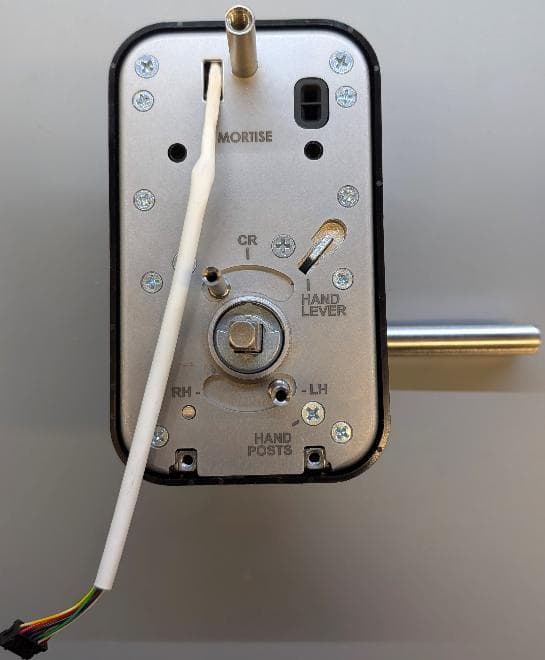
U4A-LNK100
Sep 03, 2026Real-Time Wireless Locks
Equipment Class
DTS - Digital Transmission System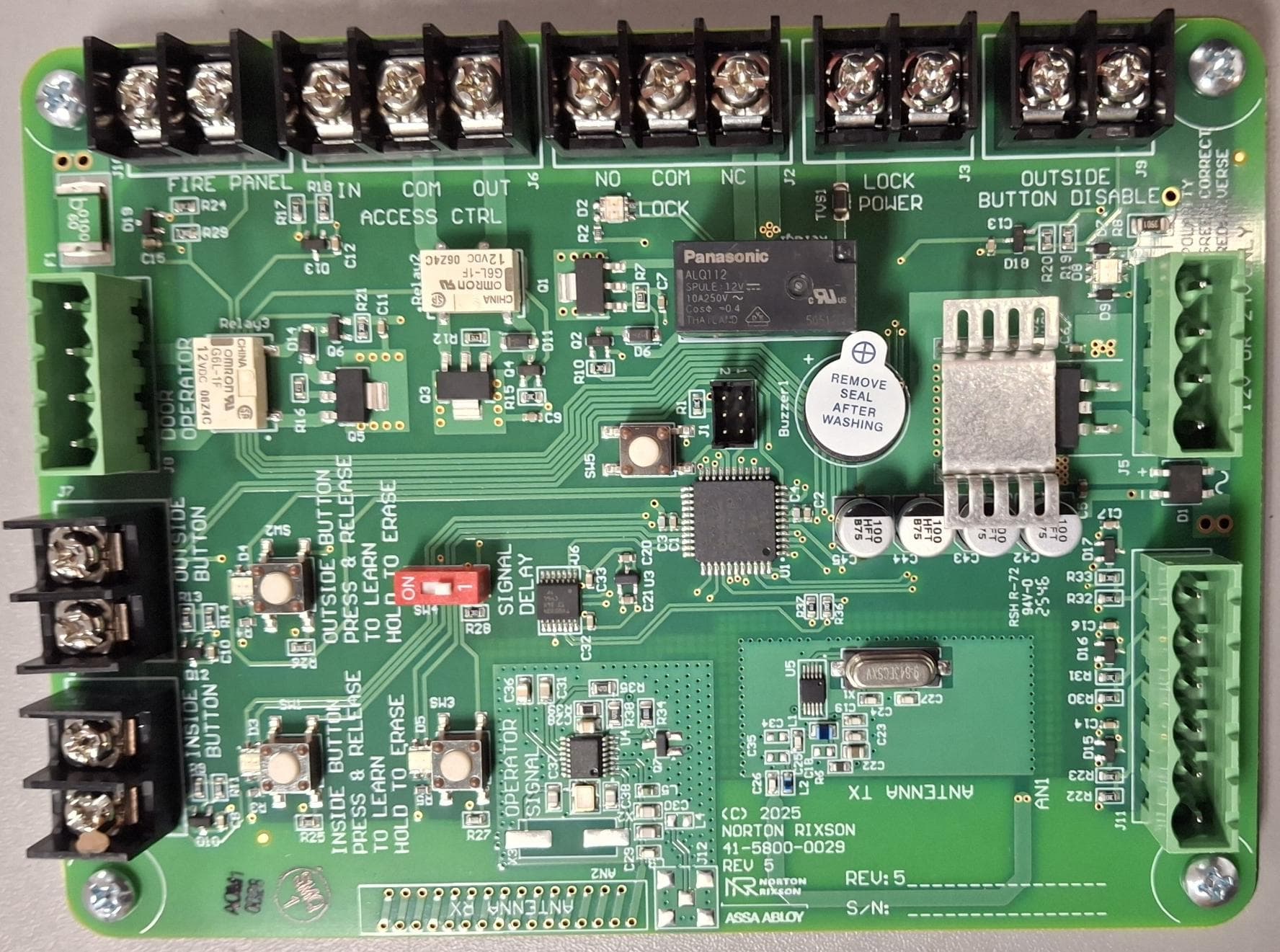
U4A-ADA1028W2
Aug 07, 2026Wireless Interface Device
Equipment Class
DSR - Part 15 Remote Control/Security Device Transceiver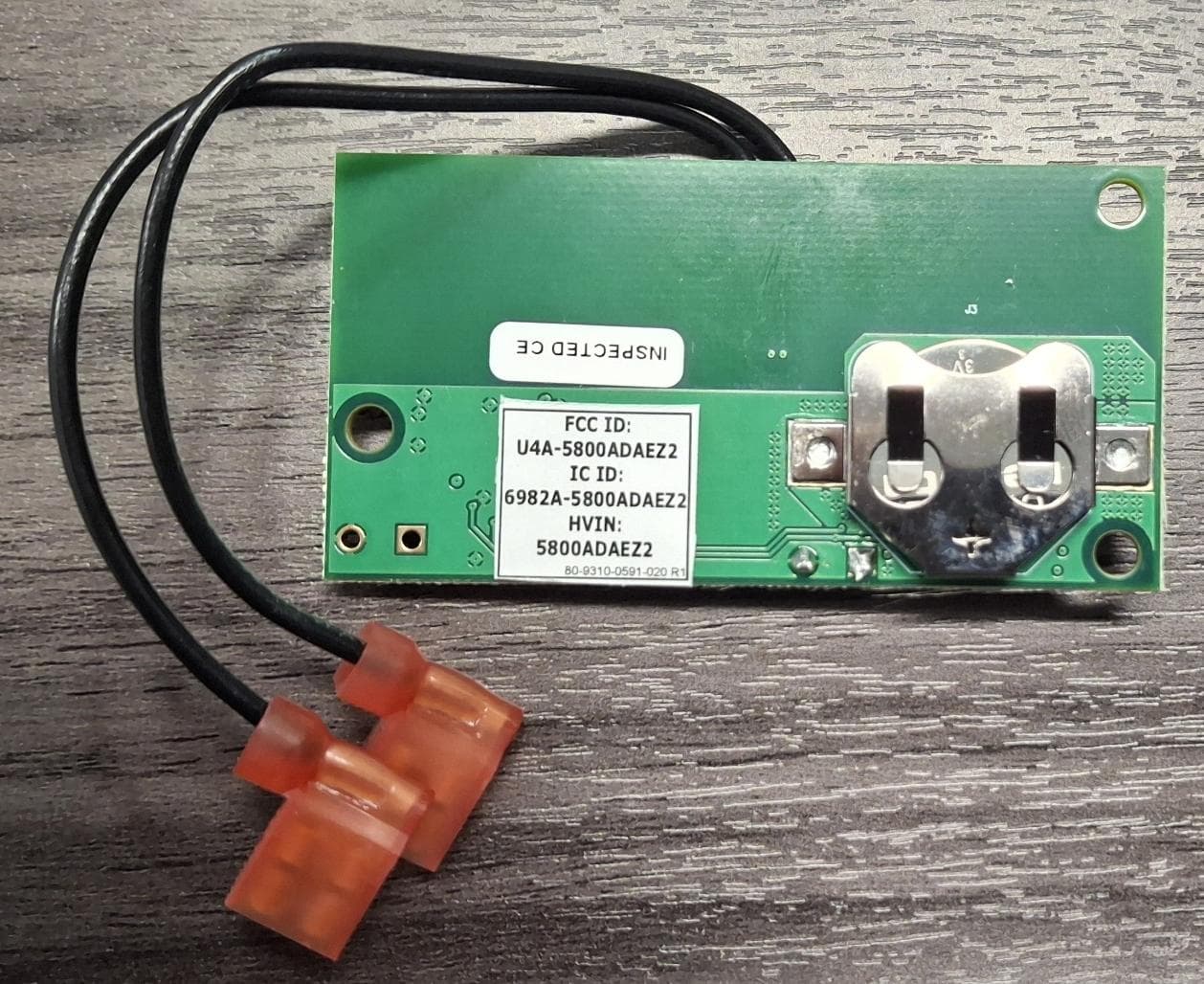
U4A5800ADAEZ2
Feb 20, 2026Wireless Interface Device
Equipment Class
DSR - Part 15 Remote Control/Security Device Transceiver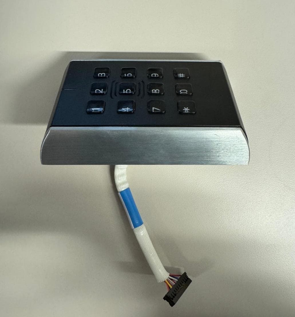
U4A-SCYMCA1K
Jul 28, 2024Aperio V3 IN100 Keypad Variant RF Module
Equipment Class
DXX - Part 15 Low Power Communication Device Transmitter
U4A-YRHCPMT1FM
Mar 27, 2023Wireless Module to add BLE or Thread capabilities to Smart Door Locks
Equipment Class
DTS - Digital Transmission System