U4A-HCPZB231LFMWireless Module for Door Lock
ASSA ABLOY Inc.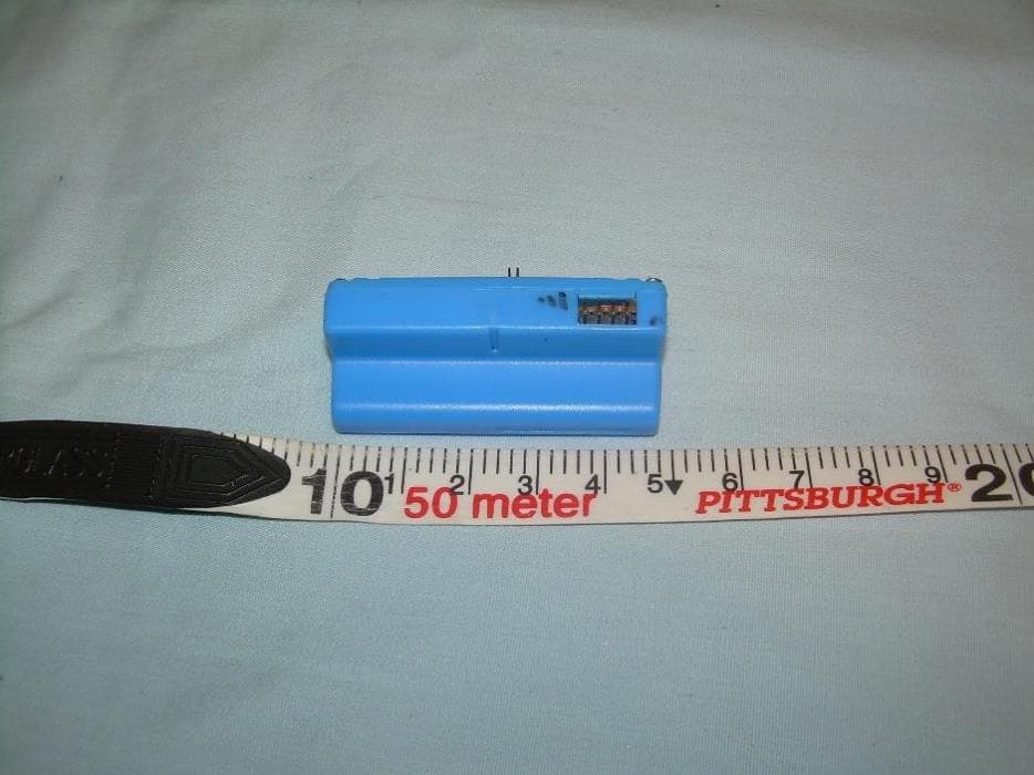
Click to zoom
Application Details
- Equipment Class
- DTS - Digital Transmission System
- Date of Grant
- May 02, 2021
- Application Purpose
- Original Equipment
- Date of Application
- May 02, 2021
- Equipment Note
- Wireless Module for Door Lock
- Frequency Range
- 2405.00000000 - 2475.00000000
- Company
- ASSA ABLOY Inc.
- Country
- United States
Documents & Files
Document Text
Text extracted from the exhibit documents filed with the FCC. Open a document above to read the original.
Cover Letter(s)
1/27/21 Agent’s Authorization Letter FCC ID U4A-HCPZB231LFM I, an employee of ASSA ABLOY, do hereby authorize, until further notice, Jason Stewart of VPI Laboratories, 313 W 12800 S, Suite 311, Draper, UT 84020, to act on our behalf in dealings before the Federal Communications Commission with respect to all matters relating to equipment authorizations under 47 CFR. This authorization includes, but is not limited to, the signing of Form 731. I certify that no party (as defined in 47 CFR 1.2002) to this application, including myself, is subject to a denial of federal benefits, that include FCC benefits, pursuant to section 5301 of the Anti-Drug Abuse Act of 1988, 21 U.S.C., 853A Certified By: James W. Forte, P.E. Senior Product Compliance Engineer ASSA ABLOY 110 Sargent Drive New Haven, CT. 06511 Phone: (203) 821-5788 [email protected]
Cover Letter(s)
1/27/21 Federal Communications Commission 7435 Oakland Mills Road Columbia, MD 21046-1609 Re: Confidentiality Request Dear Sir/Madam: This letter is to comply with 47 CFR 0.457(d)(2) and 0.459 pertaining to confidential material. ASSA ABLOY Inc. requests that the following documents regarding this submission for FCC ID U4A-HCPZB231LFM be kept confidential. 1. Schematics 2. Block Diagram 3. Theory of Operation The materials above have been developed at considerable effort and expense by ASSA ABLOY Inc. These items are considered as Trade Secrets and therefore public access to the proprietary material could possibly result in duplication of equipment that could severely damage the company's business advantage. Sincerely, James W. Forte, P.E. Senior Product Compliance Engineer ASSA ABLOY 110 Sargent Drive New Haven, CT. 06511 Phone: (203) 821-5788 [email protected]
Cover Letter(s)
April 27, 2021 Federal Communications Commission 7435 Oakland Mills Road Columbia, MD 21046-1609 CC: Curtis-Straus LLC TCB Re: Single Modular Approval Request To Whom It May Concern, We, ASSA ABLOY Inc., are applying for a full modular approval for our device with FCC ID: U4A-HCPZB231LFM Please note that, this module is to be installed only by us in our end products and will not be marketed to any other party. Installation will be under our control and therefore full compliance of the end product will always be ensured. The following information is being provided regarding full modular approval per the requirements of CFR 47 FCC 15.212(b). This transceiver is a complete RF module with an integral reference oscillator. External connections are provided for power and data communication. Antennas are external to our module. The following numbered items correspond to requirements listed in 15.212 of the FCC rules. 1) The radio elements of the modular transmitter must have their own shielding. The physical crystal and tuning capacitors may be located external to the shielded radio elements. The module is provided with a shield. 2) The modular transmitter must have buffered modulation/data inputs (if such inputs are provided) to ensure that the module will comply with part 15 requirements under conditions of excessive data rates or over-modulation. The module is designed using a System on Chip (SoC) solution. There are no exposed modulation inputs. 3) The modular transmitter must have its own power supply regulation. The power supply is regulated as per the schematic diagram. 4) The modular transmitter must comply with the antenna and transmission system requirements of Sec. Sec. 15.203, 15.204(b) and 15.204(c). The antenna must either be permanently attached or employ a ``unique'' antenna coupler (at all connections between the module and the antenna, including the cable). The ``professional installation'' provision of Sec. 15.203 is not applicable to modules but can apply to limited modular approvals under paragraph (b) of this section. The antenna is permanently attached to the module. They are not detachable and therefore our module complies with this requirement. 5) The modular transmitter must be tested in a stand-alone configuration, i.e., the module must not be inside another device during testing for compliance with part 15 requirements. Unless the transmitter module will be battery powered, it must comply with the AC line conducted requirements found in Sec. 15.207. AC or DC power lines and data input/output lines connected to the module must not contain ferrites, unless they will be marketed with the module (see Sec. 15.27(a)). The length of these lines shall be the length typical of actual use or, if that length is unknown, at least 10 centimeters to insure that there is no coupling between the case of the module and supporting equipment. Any accessories, peripherals, or support equipment connected to the module during testing shall be unmodified and commercially available (see Sec. 15.31(i)). Our module was tested in stand-alone configuration and therefore complies with this requirement. 6) The modular transmitter must be equipped with either a permanently affixed label or must be capable of electronically displaying its FCC identification number. If using a permanently affixed label, the modular transmitter must be labeled with its own FCC identification number, and, if the FCC identification number is not visible when the module is installed inside another device, then the outside of the device into which the module is installed must also display a label referring to the enclosed module. This exterior label can use wording such as the following: “Contains Transmitter Module FCC ID: XYZMODEL1” or “Contains FCC ID:XYZMODEL1.” Any similar wording that expresses the same meaning may be used. The Grantee may either provide such a label, an example of which must be included in the application for equipment authorization, or, must provide adequate instructions along with the module which explain this requirement. In the latter case, a copy of these instructions must be included in the application for equipment authorization. Our module has a label as described in the label exhibit that complies with this requirement. End-product labeling warnings can be found in the installation manual of the module. 7) The modular transmitter must comply with any specific rules or operating requirements that ordinarily apply to a complete transmitter and the manufacturer must provide adequate instructions along with the module to explain any such requirements. A copy of these instructions must be included in the application for equipment authorization. Our module complies with this requirement. 8) The modular transmitter must comply with any applicable RF exposure requirements in its final configuration. Our module complies with this requirement. This module is to be installed only by us in our end products and will not be marketed to any other party. Installation will be under our control and therefore full compliance of the end product will always be ensured. Sincerely, James W. Forte, P.E. Senior Product Compliance Engineer
External Photos
313 West 12800 South, Suite 311, Draper, UT 84020 • (801) 260-4040 TUMBLER_ExtPho.docx Page 1 of 4 PROPRIETARY External Photographs Photograph 1 – Front View of the EUT 313 West 12800 South, Suite 311, Draper, UT 84020 • (801) 260-4040 TUMBLER_ExtPho.docx Page 2 of 4 PROPRIETARY Photograph 2 – Back View of the EUT 313 West 12800 South, Suite 311, Draper, UT 84020 • (801) 260-4040 TUMBLER_ExtPho.docx Page 3 of 4 PROPRIETARY Photograph 3 – View of the Right Side of the EUT 313 West 12800 South, Suite 311, Draper, UT 84020 • (801) 260-4040 TUMBLER_ExtPho.docx Page 4 of 4 PROPRIETARY Photograph 4 – View of the Left Side of the EUT
Internal Photos
313 West 12800 South, Suite 311, Draper, UT 84020 • (801) 260-4040 TUMBLER_IntPho.docx Page 1 of 2 PROPRIETARY Internal Photographs Photograph 1 – Top View of the PCB with Shield Photograph 2 – View of the Bottom Side of the PCB PCB Antenna 313 West 12800 South, Suite 311, Draper, UT 84020 • (801) 260-4040 TUMBLER_IntPho.docx Page 2 of 2 PROPRIETARY Photograph 3 – View of the Circuitry under the RF Shield
RF Exposure Info
313 West 12800 South, Suite 311, Draper, UT 84020 • (801) 260-4040 Tumbler-L_MPE.docx Page 1 of 2 PROPRIETARY 47 C.F.R. Part 1, Subpart I, Section 1.1310 47 C.F.R. Part 2, Subpart J, Section 2.1091 Maximum Permissible Exposure Calculations For FCC ID: U4A-HCPZB231LFM EUT Device Category = General Population/Uncontrolled Exposure EUT consists of one ISM band radio transmitting over a range of: 2402 MHz to 2480 MHz MPE Summary: According subpart 1.1307 (b)(1) and 2.1091 systems operating under the provisions of this section shall be operated in a manner that ensures the public is not exposed to RF energy level in excess of the communication guidelines. Limits for General Population/Uncontrolled Exposure Limits for General Population/Uncontrolled Exposure Frequency Range (MHz) Electric Field Strength (V/m) Magnetic Field Strength (A/m) Power Density (mW/cm2) Averaging Time (Minutes) 0.3-1.34 614 1.63 *(100) 30 1.34-30 824/f 2.19/f *(180/f2) 30 30-300 27.5 0.073 0.2 30 300-1500 / / f/1500 30 1500-100,000 / / 1.0 30 f = frequency in MHz; * = Plane-wave equivalent power density Calculated Formulary: Predication of MPE limit at a given distance S = power density (in appropriate units, e.g. mW/cm 2 ) R = distance to the center of radiation of the antenna (appropriate units, e.g., cm) PG = EIRP 313 West 12800 South, Suite 311, Draper, UT 84020 • (801) 260-4040 Tumbler-L_MPE.docx Page 2 of 2 PROPRIETARY MPE and Limit are calculated for this device as follows: BLE Transceiver Freq Max EIRP (dBm) Max EIRP (mW) Power Density at 20 cm (mW/cm 2 ) Limit (mW/cm 2 ) Margin (mW) 2402 7.650 5.821 0.001 1.000 0.999 2440 8.830 7.638 0.002 1.000 0.998 2480 9.080 8.091 0.002 1.000 0.998 Result: The device meets FCC MPE limit at 20 cm for General Population/Uncontrolled Exposure as specified in 47 CRF §1.1310 and §2.1091.
Test Report
313 West 12800 South, Suite 311 Draper, UT 84020 (801) 260-4040 Test Report Certification FCC ID U4A-HCPZB231LFM Equipment Under Test ZB-Tumbler231L Test Report Serial No V056213_02 Dates of Test December 10 & 14, 2020 Report Issue Date February 3, 2021 Test Specifications: Applicant: FCC Part 15, Subpart C Assa Abloy 110 Sargent Drive New Haven, CT 06511 U.S.A. 313 West 12800 South, Suite 311, Draper, UT 84020 • (801) 260-4040 V056213_02_Tumbler-L_FCC_Sub_C.docx Page 2 of 37 PROPRIETARY Certification of Engineering Report This report has been prepared by VPI Laboratories, Inc. to document compliance of the device described below with the requirements of Federal Communications Commission (FCC) Part 15, Subpart C. This report may be reproduced in full. Partial reproduction of this report may only be made with the written consent of the laboratory. The results in this report apply only to the sample tested. Applicant Assa Abloy Manufacturer Assa Abloy Brand Name YALE Model Number ZB-Tumbler231L FCC ID U4A-HCPZB231LFM On this 3 rd day of February 2021, I, individually and for VPI Laboratories, Inc., certify that the statements made in this engineering report are true, complete, and correct to the best of my knowledge, and are made in good faith. Although NVLAP has accredited the VPI Laboratories, Inc. EMC testing facilities, this report must not be used to claim product certification, approval, or endorsement by NVLAP, NIST, or any agency of the federal government. VPI Laboratories, Inc. Tested by: Norman P. Hansen Reviewed by: Benjamin N. Antczak 313 West 12800 South, Suite 311, Draper, UT 84020 • (801) 260-4040 V056213_02_Tumbler-L_FCC_Sub_C.docx Page 3 of 37 PROPRIETARY Revision History Revision Description Date 01 Original Report Release February 3, 2021 02 Correct error in lower channel spurious emission table Correct FCC-ID April 22, 2021 313 West 12800 South, Suite 311, Draper, UT 84020 • (801) 260-4040 V056213_02_Tumbler-L_FCC_Sub_C.docx Page 4 of 37 PROPRIETARY Table of Contents 1 Client Information ................................................................................................................................. 5 1.1 Applicant ....................................................................................................................................... 5 1.2 Manufacturer ................................................................................................................................. 5 2 Equipment Under Test (EUT) ............................................................................................................... 6 2.1 Identification of EUT .................................................................................................................... 6 2.2 Description of EUT ....................................................................................................................... 6 2.3 EUT and Support Equipment ........................................................................................................ 6 2.4 Interface Ports on EUT ................................................................................................................. 7 2.5 Modification Incorporated/Special Accessories on EUT .............................................................. 7 2.6 Deviation from Test Standard ....................................................................................................... 7 3 Test Specification, Methods and Procedures ........................................................................................ 8 3.1 Test Specification .......................................................................................................................... 8 3.2 Methods & Procedures .................................................................................................................. 8 3.3 Test Procedure ............................................................................................................................ 12 4 Operation of EUT During Testing ...................................................................................................... 13 4.1 Operating Environment ............................................................................................................... 13 4.2 Operating Modes ......................................................................................................................... 13 4.3 EUT Exercise Software ............................................................................................................... 13 5 Summary of Test Results .................................................................................................................... 14 5.1 FCC Part 15, Subpart C .............................................................................................................. 14 5.2 Result .......................................................................................................................................... 14 6 Measurements, Examinations and Derived Results ............................................................................ 15 6.1 General Comments ...................................................................................................................... 15 6.2 Test Results ................................................................................................................................. 15 7 Test Procedures and Test Equipment .................................................................................................. 26 7.1 Conducted Emissions at Mains Ports .......................................................................................... 26 7.2 Radiated Emissions ..................................................................................................................... 27 7.3 Equipment Calibration ............................................................................................................…
Text truncated - open the document above for the full version.
Test Setup Photos
313 West 12800 South, Suite 311, Draper, UT 84020 • (801) 260-4040 TUMBLER_Tsup.docx Page 1 of 7 PROPRIETARY Test Set Up Photographs Radiated Photograph 1: Front View Radiated Emissions, Worst Case – Below 1000 MHz Configuration Photograph 2: Back View Radiated Emissions Worst Case 30 MHz to 1000 Configuration 313 West 12800 South, Suite 311, Draper, UT 84020 • (801) 260-4040 TUMBLER_Tsup.docx Page 2 of 7 PROPRIETARY Photograph 3: Front View Radiated Emissions Worst Case – Above 1000 MHz Configuration Photograph 4: Back View Radiated Emissions Worst Case – Above 1000 MHz Configuration 313 West 12800 South, Suite 311, Draper, UT 84020 • (801) 260-4040 TUMBLER_Tsup.docx Page 3 of 7 PROPRIETARY Photograph 5: Front View Conducted Emissions Worst-Case Configuration Photograph 6: Back View Conducted Emissions Worst-Case Configuration 313 West 12800 South, Suite 311, Draper, UT 84020 • (801) 260-4040 TUMBLER_Tsup.docx Page 4 of 7 PROPRIETARY Photograph 7: Flat Placement Worst Case Photograph 8: Edge Placement 313 West 12800 South, Suite 311, Draper, UT 84020 • (801) 260-4040 TUMBLER_Tsup.docx Page 5 of 7 PROPRIETARY Photograph 9: Vertical Placement 313 West 12800 South, Suite 311, Draper, UT 84020 • (801) 260-4040 TUMBLER_Tsup.docx Page 6 of 7 PROPRIETARY Reference Test Set Up Photographs Photograph 10: Reference Photo of Test Setup for Emissions Below 30 MHz Photograph 11: Reference Photo of Test Setup for Emissions From 30 MHz to 1000 MHz 313 West 12800 South, Suite 311, Draper, UT 84020 • (801) 260-4040 TUMBLER_Tsup.docx Page 7 of 7 PROPRIETARY Photograph 12: Reference Photo of Test Setup for Emissions Above 1000 MHz
Contact Information
Applicant
James Forte(Senior Product Compliance Engineer)
Test Firm
VPI TechnologyJason Stewart
[email protected]801-495-2310
Technical Specifications
| # | Rule Parts | Frequency Range | Power Output |
|---|---|---|---|
| 1 | 15C | 2.40 GHz - 2.48 GHz | 5.10 mW |
Other Applications from ASSA ABLOY Inc.
U4A-LNK100
Sep 03, 2026Real-Time Wireless Locks
Equipment Class
DTS - Digital Transmission System
U4A-ADA1028W2
Aug 07, 2026Wireless Interface Device
Equipment Class
DSR - Part 15 Remote Control/Security Device Transceiver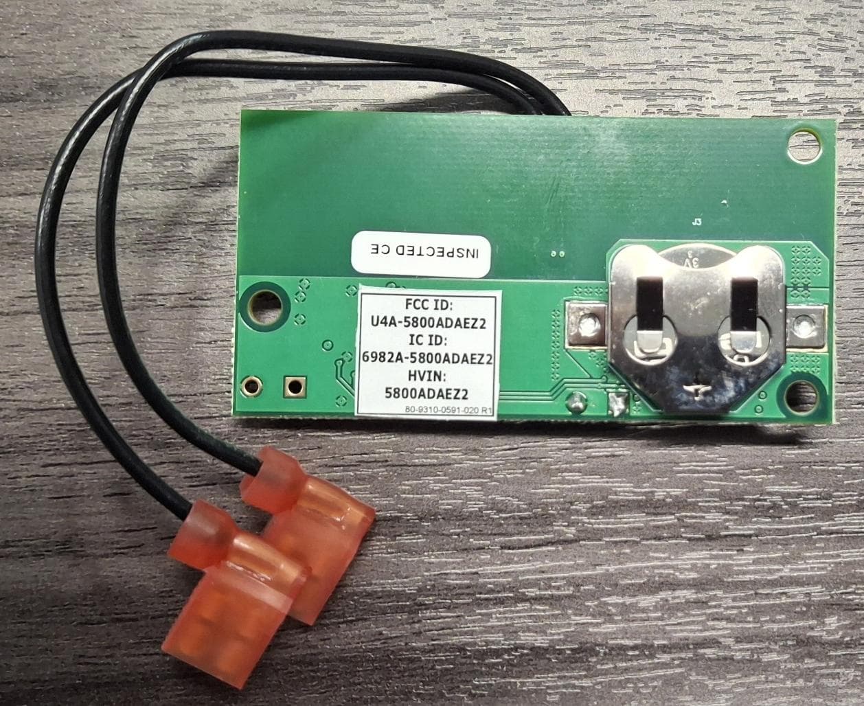
U4A5800ADAEZ2
Feb 20, 2026Wireless Interface Device
Equipment Class
DSR - Part 15 Remote Control/Security Device Transceiver
U4A-SCYMCA1K
Jul 28, 2024Aperio V3 IN100 Keypad Variant RF Module
Equipment Class
DXX - Part 15 Low Power Communication Device Transmitter
U4A-CEX100
Jun 05, 2023Access Control Lock
Equipment Class
DXX - Part 15 Low Power Communication Device Transmitter