U4A-YRHCPMT1FMWireless Module to add BLE or Thread capabilities to Smart Door Locks
ASSA ABLOY Inc.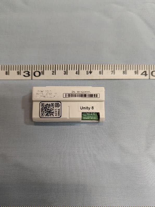
Click to zoom
Application Details
- Equipment Class
- DTS - Digital Transmission System
- Date of Grant
- Mar 27, 2023
- Application Purpose
- Original Equipment
- Date of Application
- Mar 27, 2023
- Equipment Note
- Wireless Module to add BLE or Thread capabilities to Smart Door Locks
- Frequency Range
- 2405.00000000 - 2480.00000000
- Company
- ASSA ABLOY Inc.
- Country
- United States
Documents & Files
Document Text
Text extracted from the exhibit documents filed with the FCC. Open a document above to read the original.
Users Manual
Trusted every day Internal Part of ASSA ABLOY Assure Lock + Matter Installation Yale 2021 Trusted every day Internal Step 1 2 Trusted every day Internal Step 2 3 Trusted every day Internal Step 3 4 Trusted every day Internal Step 4 5 Trusted every day Internal Step 5 6 Trusted every day Internal Step 6 7 Trusted every day Internal Step 7 8 Trusted every day Internal Step 8 9 Trusted every day Internal Step 9 10 Internal © ASSA ABLOY Trusted every day Part of ASSA ABLOY
Users Manual
Let’s get started. Commençons. For the best experience, scan the QR Code using your phone’s camera app before going to your smart home app. Pour une expérience optimale, scannez le code QR avec la caméra de votre téléphone avant d’accéder à votre application de maison intelligente. R-AYR-MOD-MT1-USA-QSG Rev A We’re here to help 24/7! Nous sommes là pour vous aider: 24 heures sur 24, 7 jours sur 7! 1 855 213 5841 [email protected] support.shopyalehome.com Scan here for the Matter Setup Guide Scannez ici pour le guide de configuration Matter Model: AYR MOD MT1 USA FCC ID: U4A YRHCPMT1FM IC ID: 6982A YRHCPMT1FM Equipment: Class B This equipment has been tested and found to comply with the limits for a Class B digital device, pursuant to Part 15 of the FCC Rules. These limits are designed to provide reasonable protection against harmful interference in a residential installation. This equipment generates, uses, and can radiate radio frequency energy and, if not installed and used in accordance with the instructions, may cause harmful interference to radio communications. However, there is no guarantee that interference will not occur in a particular installation. If this equipment does cause harmful interference to radio or television reception, which can be determined by turning the equipment off and on, the user is encouraged to try to correct the interference by one or more of the following measures: • Reorient or relocate the receiving antenna. • Increase the separation between the equipment and receiver. • Connect the equipment into an outlet on a circuit different from that to which the receiver is connected. • Consult the dealer or an experienced radio/TV technician for help. THIS DEVICE COMPLIES WITH PART 15 OF THE FCC RULES. OPERATION IS SUBJECT TO THE FOLLOWING TWO CONDITIONS. (1) THIS DEVICE MAY NOT CAUSE HARMFUL INTERFERENCE, AND (2) THIS DEVICE MUST ACCEPT ANY INTERFERENCE RECEIVED, INCLUDING INTERFERENCE THAT MAY CAUSE UNDESIRED OPERATION. This equipment complies with FCC radiation exposure limits set forth for an uncontrolled environment. This equipment should be installed and operated with minimum distance 20cm between the radiator & your body. Warning: Changes or modifications to this device, not expressly approved by Yale Home could void the user’s authority to operate the equipment. Under Industry Canada regulations, this radio transmitter may only operate using an antenna of a type and maximum (or lesser) gain approved for the transmitter by Industry Canada. To reduce potential radio interference to other users, the antenna type and its gain should be so chosen that the equivalent isotropically radiated power (e.i.r.p.) is not more than that necessary for successful communication. This Device complies with Industry Canada License-exempt RSS standard(s). Operation is subject to the following two conditions: 1) this device may not cause interference, and 2) this device must accept any interference, including interference that may cause undesired operation of the device. CAN ICES 3B/NMB 3B Copyright © 2003 2023 Connectivity Standards Alliance. All Rights Reserved. The Alliance’s Brands and all goodwill associated therewith, are the exclusive property of the Alliance. Specifications published by Alliance are the exclusive property (copyright) of the Alliance and may only be used in a manner as specified by the Alliance. Module is limited to install ONLY with the Yale door locks. ASSA ABLOY, INC is responsible for ensuring that the end-user has no manual instructions to remove or install module and must be provided labeling requirements for finished products. Module is limited to installation in mobile or fixed applications, according to Part 2.1091(b). A separate approval is required for all other operating configurations, including portable configurations with respect to Part 2.1093 and different antenna configurations. Modèle: AYR MOD MT1 USA ID FCC: U4A YRHCPMT1FM ID IC: 6982A YRHCPMT1FM Équipement: Classe B Ce dispositif a fait l’objet de tests et respecte les seuils autorisés pour les appareils numériques de Classe B, conformément à la partie 15 des Règles de la FCC. Ces limites sont conçues dans le but d’assurer une protection raisonnable contre les interférences nuisibles dans les installations résidentielles. Cet équipement génère, utilise, et peut émettre des rayonnements de radiofréquence et, s’il n’est pas installé et employé conformément aux instructions, peut produire des interférences nuisibles avec les transmissions radio. Toutefois, il n’existe aucune garantie que des interférences ne se produiront pas dans une installation donnée. Si ce dispositif cause des interférences avec la réception de signaux de radio ou de télévision, ce qui peut être détecté en l’éteignant et en le rallumant, l’utilisateur peut essayer de corriger le problème de l’une des manières suivantes: • Réorienter ou déplacer l’antenne de réception. • Augmenter la distance séparant l’appareil et le récepteur. • Connecter l’appareil à une prise électrique située sur un autre circuit que celui sur lequel est branché le récepteur. • Prenez contact avec le vendeur ou un technicien radio/TV expérimenté pour obtenir de l’aide. CE DISPOSITIF RESPECTE LA SECTION 15 DES DIRECTIVES DE LA FCC. SON OPÉRATION EST SOUMISE AUX DEUX CONDITIONS SUIVANTES : (1) CET APPAREIL NE DOIT PAS CAUSER D'INTERFÉRENCES NUISIBLES ET (2) CET APPAREIL DOIT ACCEPTER TOUTE INTERFÉRENCE REÇUE, Y COMPRIS LES INTERFÉRENCE SUSCEPTIBLES D’EN COMPROMETTRE LE FONCTIONNEMENT. Cet équipement est conforme aux limites d'exposition aux radiations définies par la FCC pour un environnement non contrôlé. Cet équipement doit être installé et utilisé avec une distance minimale de 20 cm entre le radiateur et votre corps. Avertissement: Tout changement ou modification de cet appareil, non expressément approuvé par Yale Home, peut annuler le droit de l’utilisateur à faire fonctionner l’équipement. En vertu des règlements d’Industrie Canada, ce…
Text truncated - open the document above for the full version.
Attestation Statements
Rev 1/26/2023 Federal Communications Commission Authorization and Evaluation Division 7435 Oakland Mills Road Columbia, MD 21046 USA Date: 03-22-2023 Ref: Attestation Statements Part 2.911(d)(7) Filing FCC ID: U4A-YRHCPMT1FM ASSA ABLOY (“the applicant”) certifies that, as of the date of the filing of the application, we designate ourselves as the U.S. agent for service of process. Designated U.S. Agent Information: FRN: 0016550824 Name: ASSA ABLOY Address: 110 Sargent Dr., New Haven, CT 06511 Contact Person: James Forte Tel.: 203-821-5788 Email: [email protected] Sincerely, James W. Forte, P.E. Senior Product Compliance Engineer
Cover Letter(s)
FCC MODULAR APPROVAL REQUEST (per Part 15.212 / KDB 996369 D01) FCC ID: U4A-YRHCPMT1FM ITEMS TO BE COVERED ANSWER FROM APPLICANT 1. The radio elements must have the radio frequency circuitry shielded. Physical components and tuning capacitor(s) may be located external to the shield but must be on the module assembly. Yes, Refer to photo exhibit 2. The module must have buffered modulation/data inputs to ensure that the device will comply with Part 15 requirements with any type of input signal; Yes, refer to schematics exhibits 3. The module must contain power supply regulation on the module; Yes, refer to schematics exhibits 4. The module must contain a permanently attached antenna, or contain a unique antenna connector, and be marketed and operated only with specific antenna(s), per §§ 15.203, 15.204(b), 15.204(c), 15.212(a), 2.929(b); Yes, refer to photo exhibit 5. The module must demonstrate compliance in a stand-alone configuration; Yes, Refer to Test Report 6. The module must be labeled with its permanently affixed FCC ID label, or use an electronic display (see KDB Publication 784748); Yes, refer to label sample exhibit 7. The module must comply with all specific rules applicable to the transmitter, including all the conditions provided in the integration instructions by the grantee; Yes, refer to operational descriptions and test reports exhibits 8. The module must comply with RF exposure requirements (see Clause V below). Yes, refer to MPE exhibit Name of Applicant (or Authorized Representative):Jason Stewart, Director Laboratories, VPI Laboratories Date: 02/02/2023 Signature:
Cover Letter(s)
12/2/22 Federal Communications Commission 7435 Oakland Mills Road Columbia, MD 21046-1609 Re: Confidentiality Request Dear Sir/Madam: This letter is to comply with 47 CFR 0.457(d)(2) and 0.459 pertaining to confidential material. ASSA ABLOY Inc. requests that the following documents regarding this submission for FCC ID U4A-YRHCPMT1FM be kept confidential. 1. Schematics 2. Block Diagram 3. Theory of Operation 4. Bill of Materials The materials above have been developed at considerable effort and expense by ASSA ABLOY Inc. These items are considered as Trade Secrets and therefore public access to the proprietary material could possibly result in duplication of equipment that could severely damage the company's business advantage. Sincerely, James W. Forte, P.E. Senior Product Compliance Engineer ASSA ABLOY 110 Sargent Drive New Haven, CT. 06511 Phone: (203) 821-5788 [email protected]
Cover Letter(s)
12/2/22 Agent’s Authorization Letter FCC ID U4A-YRHCPMT1FM I, an employee of ASSA ABLOY, do hereby authorize, until further notice, Jason Stewart at VPI Laboratories, 313 W 12800 S, Draper, UT 84020, to act on our behalf in dealings before the Federal Communications Commission with respect to all matters relating to equipment authorizations under 47 CFR. This authorization includes, but is not limited to, the signing of Form 731. I certify that no party (as defined in 47 CFR 1.2002) to this application, including myself, is subject to a denial of federal benefits, that include FCC benefits, pursuant to section 5301 of the Anti-Drug Abuse Act of 1988, 21 U.S.C., 853A Certified By: James W. Forte, P.E. Senior Product Compliance Engineer ASSA ABLOY 110 Sargent Drive New Haven, CT. 06511 Phone: (203) 821-5788 [email protected]
External Photos
313 West 12800 South, Suite 311, Draper, UT 84020 • (801) 260-4040 MORT_ExtPho.docx Page 1 of 6 PROPRIETARY External Photographs Photograph 1 – Top View of the EUT 313 West 12800 South, Suite 311, Draper, UT 84020 • (801) 260-4040 MORT_ExtPho.docx Page 2 of 6 PROPRIETARY Photograph 2 – Bottom View of the EUT 313 West 12800 South, Suite 311, Draper, UT 84020 • (801) 260-4040 MORT_ExtPho.docx Page 3 of 6 PROPRIETARY Photograph 3 – Side View of the EUT 313 West 12800 South, Suite 311, Draper, UT 84020 • (801) 260-4040 MORT_ExtPho.docx Page 4 of 6 PROPRIETARY Photograph 4 – Side View of the EUT 313 West 12800 South, Suite 311, Draper, UT 84020 • (801) 260-4040 MORT_ExtPho.docx Page 5 of 6 PROPRIETARY Photograph 5 – Front View of the EUT 313 West 12800 South, Suite 311, Draper, UT 84020 • (801) 260-4040 MORT_ExtPho.docx Page 6 of 6 PROPRIETARY Photograph 6 – Back View of the EUT
ID Label/Location Info
SN: XXXXXXXXXX Model: AYR-MOD-MT1-USA FCC ID: U4A-YRHCPMT1FM IC: 6982A-YRHCPMT1FM SN: XXXXXXXXXX Model: AYR-MOD-MT1-USA FCC ID: U4A-YRHCPMT1FM IC: 6982A-YRHCPMT1FM COLOR LEGEND GreenIndicators (not printed) MagentaBody Border (not printed) ARTWORK NO.DEFAULT TOLERANCES 085-01022 DRAWING NAME Artwork,Label,Serial Number and FCC ID,Unit,Matter .X ± .25 .XX ± .1 Decimal DRAWING BY Gregory Mack COLOR MATCH Pantone 116C Unless otherwise specified, dimensions are in mm. Page 1 of 1 DATE REV 0 09/30/2022 111/23/2022 2--/--/-- DATE BlackPrinted in Black BlueDynamic ARTWORK LAYOUT, SCALE 2:1 ARTWORK LAYOUT, SCALE 1:1 Helvetica LT Std, Roman, 5pt Center align SN text to barcode width Barcode type 128, black ink unit serial number Helvetica LT Std, Roman, 5pt 11/23/2022
Internal Photos
313 West 12800 South, Suite 311, Draper, UT 84020 • (801) 260-4040 MORT_IntPho.docx Page 1 of 5 PROPRIETARY External Photographs Photograph 1 – Front View of the PCBA PCB Trace Antenna 313 West 12800 South, Suite 311, Draper, UT 84020 • (801) 260-4040 MORT_IntPho.docx Page 2 of 5 PROPRIETARY Photograph 2 – Back View of the PCBA 313 West 12800 South, Suite 311, Draper, UT 84020 • (801) 260-4040 MORT_IntPho.docx Page 3 of 5 PROPRIETARY Photograph 3 – View of Circuitry Under the Shield 313 West 12800 South, Suite 311, Draper, UT 84020 • (801) 260-4040 MORT_IntPho.docx Page 4 of 5 PROPRIETARY Photograph 4 – View of the PCB Mounting in the Enclosure 313 West 12800 South, Suite 311, Draper, UT 84020 • (801) 260-4040 MORT_IntPho.docx Page 5 of 5 PROPRIETARY Photograph 5 – View of the PCB in relation to housing
RF Exposure Info
313 West 12800 South, Suite 311, Draper, UT 84020 • (801) 260-4040 MORT_MPE.docx Page 1 of 2 PROPRIETARY 47 C.F.R. Part 1, Subpart I, Section 1.1310 47 C.F.R. Part 2, Subpart J, Section 2.1091 Maximum Permissible Exposure Calculations For FCC ID: U4A-YRHCPMT1FM EUT Device Category = General Population/Uncontrolled Exposure MPE Summary: According subpart 1.1307 (b)(1) and 2.1091 systems operating under the provisions of this section shall be operated in a manner that ensures the public is not exposed to RF energy level in excess of the communication guidelines. Limits for General Population/Uncontrolled Exposure Limits for General Population/Uncontrolled Exposure Frequency Range (MHz) Electric Field Strength (V/m) Magnetic Field Strength (A/m) Power Density (mW/cm2) Averaging Time (Minutes) 0.3-1.34 614 1.63 *(100) 30 1.34-30 824/f 2.19/f *(180/f2) 30 30-300 27.5 0.073 0.2 30 300-1500 / / f/1500 30 1500-100,000 / / 1.0 30 f = frequency in MHz; * = Plane-wave equivalent power density Calculated Formulary: Predication of MPE limit at a given distance S = power density (in appropriate units, e.g. mW/cm 2 ) R = distance to the center of radiation of the antenna (appropriate units, e.g., cm) PG = EIRP 313 West 12800 South, Suite 311, Draper, UT 84020 • (801) 260-4040 MORT_MPE.docx Page 2 of 2 PROPRIETARY MPE and Limit are calculated for this device as follows: BLE Transceiver Antenna Gain 2.05 dBi Freq Conducted Power (dBm) EIRP (dBm) EIRP (mW) Power Density at 20 cm (mW/cm 2 ) Limit (mW/cm 2 ) Margin (mW) 2402 -6.10 -4.05 0.394 0.00008 1.000 0.99992 2440 -5.90 -3.85 0.412 0.00008 1.000 0.99992 2480 -6.40 -4.35 0.367 0.00007 1.000 0.99993 Thread Transceiver Antenna Gain 2.05 dBi Freq Conducted Power (dBm) EIRP (dBm) EIRP (mW) Power Density at 20 cm (mW/cm 2 ) Limit (mW/cm 2 ) Margin (mW) 2405 12.9 14.95 31.261 0.00622 1.000 0.99378 2410 17.3 19.35 86.099 0.01713 1.000 0.98287 2440 17.1 19.15 82.224 0.01636 1.000 0.98364 2475 16.4 18.45 69.984 0.01392 1.000 0.98608 2480 3.2 5.25 3.350 0.00067 1.000 0.99933 Result: The device meets FCC MPE limit at 20 cm for General Population/Uncontrolled Exposure as specified in 47 CRF §1.1310 and §2.1091.
Test Report
313 West 12800 South, Suite 311 Draper, UT 84020 (801) 260-4040 Test Report Certification FCC ID FCC# U4A-YRHCPMT1FM Equipment Under Test AYR-MOD-MT1-USA Test Report Serial No V066187_02 Dates of Test October 19-21, 2022 and November 1-2, 2022 Report Issue Date December 20, 2022 Test Specifications: Applicant: FCC Part 15, Subpart C Assa Abloy 110 Sargent Drive New Haven, CT 06511 U.S.A. 313 West 12800 South, Suite 311, Draper, UT 84020 • (801) 260-4040 V066187_02_Assa-Abloy_Mortise-140_FCC_C_BLE_Thread.docx Page 2 of 68 PROPRIETARY Certification of Engineering Report This report has been prepared by VPI Laboratories, Inc. to document compliance of the device described below with the requirements of Federal Communications Commission (FCC) Part 15, Subpart C. This report may be reproduced in full. Partial reproduction of this report may only be made with the written consent of the laboratory. The results in this report apply only to the sample tested. Applicant Assa Abloy Manufacturer Smart Electronic Industrial (Dong Guan) Co., Ltd Brand Name YALE Model Number AYR-MOD-MT1-USA FCC ID FCC# U4A-YRHCPMT1FM On this 20th day of December 2022, I, individually and for VPI Laboratories, Inc., certify that the statements made in this engineering report are true, complete, and correct to the best of my knowledge, and are made in good faith. Although NVLAP has accredited the VPI Laboratories, Inc. EMC testing facilities, this report must not be used to claim product certification, approval, or endorsement by NVLAP, NIST, or any agency of the federal government. VPI Laboratories, Inc. Tested by: Benjamin Antczak Reviewed by: Jason Stewart 313 West 12800 South, Suite 311, Draper, UT 84020 • (801) 260-4040 V066187_02_Assa-Abloy_Mortise-140_FCC_C_BLE_Thread.docx Page 3 of 68 PROPRIETARY Revision History Revision Description Date 01 Original Report Release 2022 12 20 02 Correcting Device Description 2023 02 06 313 West 12800 South, Suite 311, Draper, UT 84020 • (801) 260-4040 V066187_02_Assa-Abloy_Mortise-140_FCC_C_BLE_Thread.docx Page 4 of 68 PROPRIETARY Table of Contents 1 Client Information ................................................................................................................................. 5 1.1 Applicant ....................................................................................................................................... 5 1.2 Manufacturer ................................................................................................................................. 5 2 Equipment Under Test (EUT) ............................................................................................................... 6 2.1 Identification of EUT .................................................................................................................... 6 2.2 Description of EUT ....................................................................................................................... 6 2.3 Customer Supplied Data ............................................................................................................... 7 2.4 EUT and Support Equipment ........................................................................................................ 8 2.5 Interface Ports on EUT ................................................................................................................. 8 2.6 Modification Incorporated/Special Accessories on EUT .............................................................. 8 2.7 Deviation from Test Standard ....................................................................................................... 8 3 Test Specification, Methods and Procedures ........................................................................................ 9 3.1 Test Specification .......................................................................................................................... 9 3.2 Methods & Procedures .................................................................................................................. 9 3.3 Test Procedure ............................................................................................................................ 13 4 Operation of EUT During Testing ...................................................................................................... 14 4.1 Operating Environment ............................................................................................................... 14 4.2 Operating Modes ......................................................................................................................... 14 4.3 EUT Exercise Software ............................................................................................................... 14 5 Summary of Test Results .................................................................................................................... 15 5.1 FCC Part 15, Subpart C .............................................................................................................. 15 5.2 Result .......................................................................................................................................... 15 6 Measurements, Examinations and Derived Results ............................................................................ 16 6.1 General Comments and Results .................................................................................................. 16 6.2 Test Results – BLE Modulation Mode ....................................................................................... 18 6.3 Test Results – Thread Modulation Mode .................................................................................... 32 6.4 Sample Measurement Calculations ............................................................................................. 54 7 Test Procedures and Test Equipment ................................................................…
Text truncated - open the document above for the full version.
Test Report
1 CA Engineering: Mortise IEEE802.15.4 Antenna Characterization Technical Report # TR221012-01 Mortise Antenna Characterization for IEEE802.15.4 CA Engineering 147 West Election Road Suite 200 Draper, UT 84020 801-748-4900 Fax 801-748-4901 www.caengineering.com Customer: Yale Revision: 1.0 Prepared for: Yale Engineering Prepared By: John LoudenbackPage: 1 of 9 2 CA Engineering: Mortise IEEE802.15.4 Antenna Characterization Revision Tracking Rev.AuthorRevision DescriptionDate 1.0JLInitial Draft12 Oct 2022 Customer: Yale Revision: 1.0 Prepared for: Yale Engineering Prepared By: John LoudenbackPage: 2 of 9 3 CA Engineering: Mortise IEEE802.15.4 Antenna Characterization Antenna Gain Measurement for IEEE802.15.4 This document details the measured antenna performance for the Mortise PCB antenna in a Yale Lock for the IEEE802.15.4 standard. Measurements were taken in CAE’s Piper anechoic chamber. Measured Antenna Parameters (@ 2450 MHz) ●Total Isotropic Gain: -3.07 dBi ●Peak Gain: 2.05 dBi ●Antenna Efficiency: 49.3 % Note:Antenna gain measurements are within an errorrange of +/- 1 dBi. Radiation Plots RF radiation patterns show the antenna gain (dBi) performance - at different antenna orientations in a spherical sweep. Four different orientations associated with the antenna are shown. These same orientations are shown for the RF spherical radiation patterns in the following pages. The radiation patterns include 3D plots for both horizontal and vertical polarizations of the receiving horn antenna. Customer: Yale Revision: 1.0 Prepared for: Yale Engineering Prepared By: John LoudenbackPage: 3 of 9 4 CA Engineering: Mortise IEEE802.15.4 Antenna Characterization Mortise Test Orientation In the photo below, Top and Bottom orientation labels are the top or bottom of the Yale Lock. Front and Back orientation labels are the Front and Back of the lock. These orientation labels correspond to the radiation patterns that follow. Customer: Yale Revision: 1.0 Prepared for: Yale Engineering Prepared By: John LoudenbackPage: 4 of 9 5 CA Engineering: Mortise IEEE802.15.4 Antenna Characterization Each 3D antenna gain plot has the X, Y, Z axes showing orientation of the lock in 3D space. The radiation plots show the radiation from the X-Y axis perspectives and not the Z axis. A key showing which Axis corresponds to a specific DUT orientation is shown below. In the radiation plots a solid dot indicates that the positive axis is pointing out of the screen, otherwise it is the negative axis pointing out. Axis:DUT Orientation: Positive X AxisTop Negative X AxisBottom Positive Y AxisBack Negative Y AxisFront Customer: Yale Revision: 1.0 Prepared for: Yale Engineering Prepared By: John LoudenbackPage: 5 of 9 6 CA Engineering: Mortise IEEE802.15.4 Antenna Characterization Mortise Radiation Patterns Vertical Polarization @ 2450 MHz TopBottom FrontBack Customer: Yale Revision: 1.0 Prepared for: Yale Engineering Prepared By: John LoudenbackPage: 6 of 9 7 CA Engineering: Mortise IEEE802.15.4 Antenna Characterization Horizontal Polarization @ 2450 MHz TopBottom FrontBack Customer: Yale Revision: 1.0 Prepared for: Yale Engineering Prepared By: John LoudenbackPage: 7 of 9 8 CA Engineering: Mortise IEEE802.15.4 Antenna Characterization Additional Product Photos Customer: Yale Revision: 1.0 Prepared for: Yale Engineering Prepared By: John LoudenbackPage: 8 of 9 9 CA Engineering: Mortise IEEE802.15.4 Antenna Characterization Conclusion The Mortise antenna measured well. Recent adjustments to the antenna impedance matching done by Tom Hore provided almost 1 dB increase in peak antenna gain and 0.5 dB increase in total isotropic gain. The radiation pattern of the antenna is very good with great coverage at both horizontal and vertical polarizations. This Mortise antenna for IEEE802.15.4 will perform very well. Customer: Yale Revision: 1.0 Prepared for: Yale Engineering Prepared By: John LoudenbackPage: 9 of 9
Test Setup Photos
313 West 12800 South, Suite 311, Draper, UT 84020 • (801) 260-4040 MORT_Tsup.docx Page 1 of 7 PROPRIETARY Test Set Up Photographs Radiated Photograph 1: Front View Radiated Emissions, Worst Case – Below 1000 MHz Configuration Photograph 2: Back View Radiated Emissions Worst Case 30 MHz to 1000 Configuration 313 West 12800 South, Suite 311, Draper, UT 84020 • (801) 260-4040 MORT_Tsup.docx Page 2 of 7 PROPRIETARY Photograph 3: Front View Radiated Emissions Worst Case – Above 1000 MHz Configuration Photograph 4: Back View Radiated Emissions Worst Case – Above 1000 MHz Configuration 313 West 12800 South, Suite 311, Draper, UT 84020 • (801) 260-4040 MORT_Tsup.docx Page 3 of 7 PROPRIETARY Photograph 5: Front View Conducted Emissions Worst-Case Configuration Photograph 6: Back View Conducted Emissions Worst-Case Configuration 313 West 12800 South, Suite 311, Draper, UT 84020 • (801) 260-4040 MORT_Tsup.docx Page 4 of 7 PROPRIETARY Photograph 7: Flat Placement Worst Case Photograph 8: Edge Placement 313 West 12800 South, Suite 311, Draper, UT 84020 • (801) 260-4040 MORT_Tsup.docx Page 5 of 7 PROPRIETARY Photograph 9: Vertical Placement 313 West 12800 South, Suite 311, Draper, UT 84020 • (801) 260-4040 MORT_Tsup.docx Page 6 of 7 PROPRIETARY Reference Test Set Up Photographs Photograph 10: Reference Photo of Test Setup for Emissions Below 30 MHz Photograph 11: Reference Photo of Test Setup for Emissions From 30 MHz to 1000 MHz 313 West 12800 South, Suite 311, Draper, UT 84020 • (801) 260-4040 MORT_Tsup.docx Page 7 of 7 PROPRIETARY Photograph 12: Reference Photo of Test Setup for Emissions Above 1000 MHz
Contact Information
Applicant
James Forte(Senior Product Compliance Engineer)
Test Firm
VPI TechnologyJason Stewart
[email protected]801-495-2310
Technical Specifications
| # | Rule Parts | Frequency Range | Power Output |
|---|---|---|---|
| 2 | 15C | 2.40 GHz - 2.48 GHz | 53.70 mW |
Other Applications from ASSA ABLOY Inc.
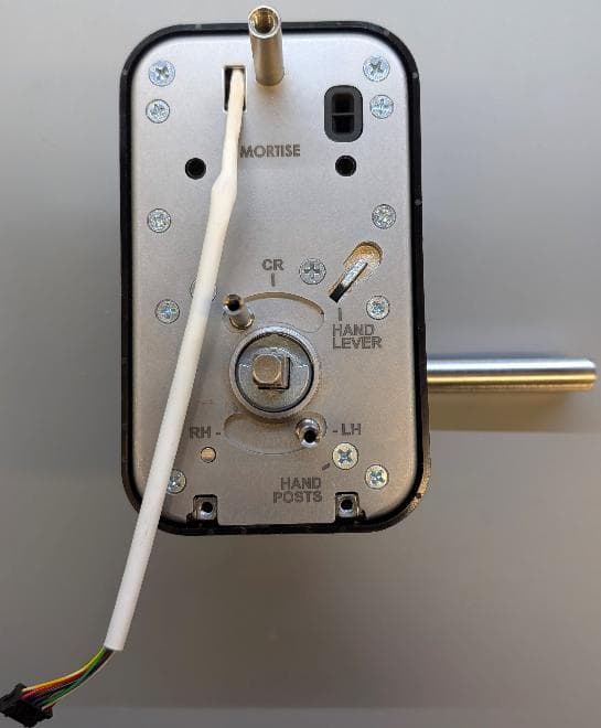
U4A-LNK100
Sep 03, 2026Real-Time Wireless Locks
Equipment Class
DTS - Digital Transmission System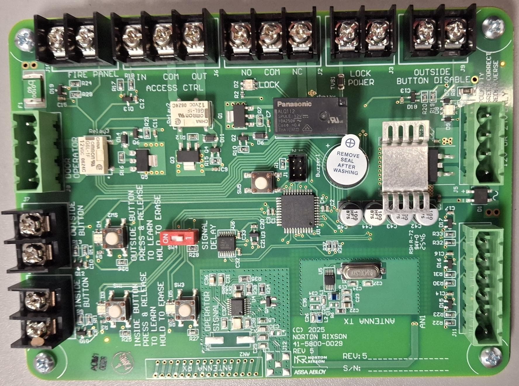
U4A-ADA1028W2
Aug 07, 2026Wireless Interface Device
Equipment Class
DSR - Part 15 Remote Control/Security Device Transceiver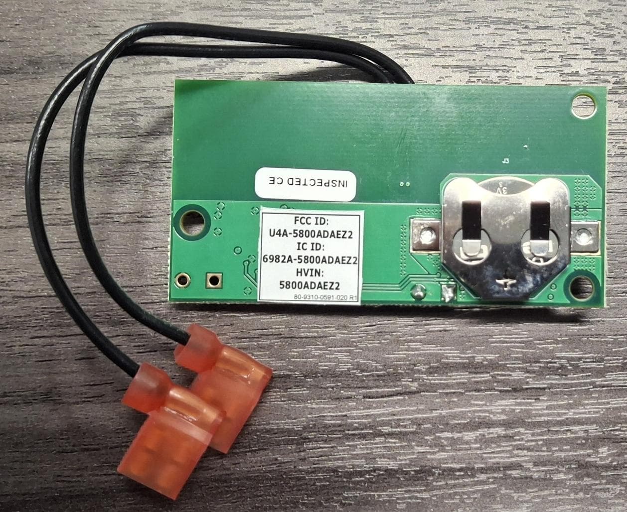
U4A5800ADAEZ2
Feb 20, 2026Wireless Interface Device
Equipment Class
DSR - Part 15 Remote Control/Security Device Transceiver
U4A-SCYMCA1K
Jul 28, 2024Aperio V3 IN100 Keypad Variant RF Module
Equipment Class
DXX - Part 15 Low Power Communication Device Transmitter
U4A-CEX100
Jun 05, 2023Access Control Lock
Equipment Class
DXX - Part 15 Low Power Communication Device Transmitter