U4A-LNK100Real-Time Wireless Locks
ASSA ABLOY Inc.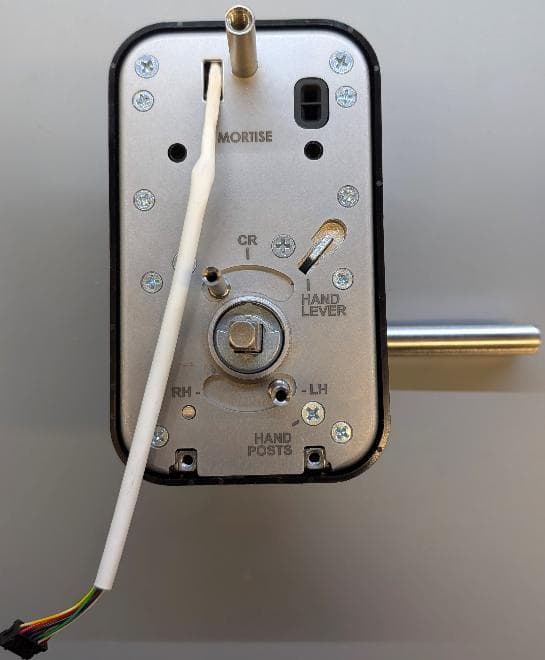
Click to zoom
Application Details
- Equipment Class
- DTS - Digital Transmission System
- Date of Grant
- Sep 03, 2026
- Application Purpose
- Original Equipment
- Equipment Note
- Real-Time Wireless Locks
- Frequency Range
- 2402.00000000 - 2480.00000000
- Company
- ASSA ABLOY Inc.
- Country
- United States
Documents & Files
Document Text
Text extracted from the exhibit documents filed with the FCC. Open a document above to read the original.
Users Manual
1-800-727-5477 • www.sargentlock.com A8416 08/26 Rev 0 Installation Instructions LNK Series LNK100 Mortise Lock with Aperio ® Technology Copyright © 2026, SARGENT Manufacturing Company. All rights reserved. Reproduction in whole or in part without the express written permission of SARGENT Manufacturing Company is prohibited. Patent pending and/or patent www.assaabloydss.com/patents. WARNING WARNING This product can expose you to lead which is known to the state of California to cause cancer and birth defects or other reproductive harm. For more information go to www.P65warnings.ca.gov. Attention Installer: Improper installation may result in damage to the product and void the factory warranty. Changes or modifications to this device not expressly approved by ASSA ABLOY could void the user’s authority to operate the equipment. 2 1-800-727-5477 www.sargentlock.com A8416 08/26 Rev 0 LNK100 Series Installation Instructions Mortise Lock Copyright © 2026, SARGENT Manufacturing Company. All rights reserved. Reproduction in whole or in part without the express written permission of SARGENT Manufacturing Company is prohibited. Patent pending and/or patent www.assaabloydss.com/patents. Table of Contents 1. Warnings........................................3 2. Regulatory and Power Specifications . . . . . . . . . . . . . . . . . . 4 General Specifications.............................................4 Electronic Authentication Specifications (Mobile Credentials) . . . . . . . . . . . . . . 4 Power Supply Specifications . . . . . . . . . . . . . . . . . . . . . . . . . . . . . . . . . . . . . . . . 4 3. Product Illustrations . . . . . . . . . . . . . . . . . . . . . . . . . . . . . . . 5 4. Lock Installation ..................................6 1. Prepare Door . . . . . . . . . . . . . . . . . . . . . . . . . . . . . . . . . . . . . . . . . . . . . . . . . 6 2. Set Latchbolt Direction (if necessary)...............................7 3. Install Lock Body . . . . . . . . . . . . . . . . . . . . . . . . . . . . . . . . . . . . . . . . . . . . . . 7 4. Reset Exterior Escutcheon Trim Posts . . . . . . . . . . . . . . . . . . . . . . . . . . . . . . 8 5. Hand Exterior Escutcheon . . . . . . . . . . . . . . . . . . . . . . . . . . . . . . . . . . . . . . . 8 6. Rehand Exterior Escutcheon (if necessary) . . . . . . . . . . . . . . . . . . . . . . . . . . 9 7. Install Exterior Escutcheon.......................................9 8. Install Interior Mounting Plate . . . . . . . . . . . . . . . . . . . . . . . . . . . . . . . . . . . 10 9. Hand Interior Escutcheon.......................................10 10. Install Interior Escutcheon . . . . . . . . . . . . . . . . . . . . . . . . . . . . . . . . . . . . . 11 11. Install Batteries and Battery Cover ..............................11 12. Install Armored Front Cover . . . . . . . . . . . . . . . . . . . . . . . . . . . . . . . . . . . 12 13. Prepare Frame and Install Strike . . . . . . . . . . . . . . . . . . . . . . . . . . . . . . . . 12 5. Operational Check . . . . . . . . . . . . . . . . . . . . . . . . . . . . . . . 13 6. Cylinder Installation . . . . . . . . . . . . . . . . . . . . . . . . . . . . . . 14 1. Removeable Core Cylinder . . . . . . . . . . . . . . . . . . . . . . . . . . . . . . . . . . . . . 14 2. Fixed Core Cylinder...........................................14 3. Removing Outside Lever . . . . . . . . . . . . . . . . . . . . . . . . . . . . . . . . . . . . . . . 15 7. Communication Hub LED Indications .................16 8. Lock LED Indications..............................17 9. Lock Self-Test LED Indications . . . . . . . . . . . . . . . . . . . . . . 19 10. Lock Busy LED Indications .........................20 3 1-800-727-5477 www.sargentlock.com LNK100 Series Installation Instructions Mortise Lock Copyright © 2026, SARGENT Manufacturing Company. All rights reserved. Reproduction in whole or in part without the express written permission of SARGENT Manufacturing Company is prohibited. Patent pending and/or patent www.assaabloydss.com/patents. A8416 08/26 Rev 0 1. Warnings FCC: This equipment has been tested and found to comply with the limits for a Class B digital device, pursuant to Part 15 of the FCC Rules. These limits are designed to provide reasonable protection against harmful interference in a residential installation. This equipment generates, uses, and can radiate radio frequency energy and, if not installed and used in accordance with the instructions, may cause harmful interference to radio communi- cations. However, there is no guarantee that interference will not occur in a particular installation. If this equipment does cause harmful interference to radio or television reception, which can be determined by turning the equipment off and on, the user is encouraged to try to correct the interference by one or more of the following measures: yReorient or relocate the receiving antenna. yIncrease the separation between the equipment and receiver. yConnect the equipment into an outlet on a circuit different from that to which the receiver is connected. yConsult the dealer or an experienced radio/TV technician for help. Any retrofit or other field modification to a fire rated opening can potentially impact the fire rating of the opening, and SARGENT Manufacturing makes no representations or warranties concerning what such impact may be in any specific situation. When retrofitting any portion of an existing fire rated opening, or specifying and installing a new fire-rated opening, please consult with a code specialist or local code official (Authority Having Jurisdiction) to ensure compliance with all applicable codes and ratings. To avoid possible damage from electrostatic discharge (ESD), some basic precautions should be used when handling electronic components: yMinimize build-up of static by touching and/or maintaining contact with unpainted metal surfaces such as door hinges, latches, and mounting plates especially when mounting ele…
Text truncated - open the document above for the full version.
Users Manual
1-800-727-5477 • www.sargentlock.com A8415 08/26 Rev 0 Installation Instructions LNK Series LNK100 Bored Lock with Aperio ® Technology Copyright © 2026, SARGENT Manufacturing Company. All rights reserved. Reproduction in whole or in part without the express written permission of SARGENT Manufacturing Company is prohibited. Patent pending and/or patent www.assaabloydss.com/patents. Attention Installer: Improper installation may result in damage to the product and void the factory warranty. Changes or modi cations to this device not expressly approved by ASSA ABLOY could void the users authority to operate the equipment. WARNING WARNING This product can expose you to lead which is known to the state of California to cause cancer and birth defects or other reproductive harm. For more information go to www.P65warnings.ca.gov. 2 1-800-727-5477 www.sargentlock.com A8415 08/26 Rev 0 LNK100 Series Installation Instructions Bored Lock Copyright © 2026, SARGENT Manufacturing Company. All rights reserved. Reproduction in whole or in part without the express written permission of SARGENT Manufacturing Company is prohibited. Patent pending and/or patent www.assaabloydss.com/patents. Table of Contents 1. Warnings........................................3 2. Regulatory and Power Specifications . . . . . . . . . . . . . . . . . . 4 General Specifications.............................................4 Electronic Authentication Specifications (Mobile Credentials) . . . . . . . . . . . . . . 4 Power Supply Specifications . . . . . . . . . . . . . . . . . . . . . . . . . . . . . . . . . . . . . . . . 5 3. Product Illustrations . . . . . . . . . . . . . . . . . . . . . . . . . . . . . . . 6 4. Lock Installation ..................................8 1. Prepare Door . . . . . . . . . . . . . . . . . . . . . . . . . . . . . . . . . . . . . . . . . . . . . . . . . 8 2. Install Latch Bolt and Door Position Sensor..........................9 3. Hand Exterior Escutcheon . . . . . . . . . . . . . . . . . . . . . . . . . . . . . . . . . . . . . . . 9 4. Rehand Exterior Escutcheon (if necessary) . . . . . . . . . . . . . . . . . . . . . . . . . 10 5. Install Retractor ..............................................10 6. Install Exterior Escutcheon Assembly on Door ......................11 7. Install Interior Mounting Plate . . . . . . . . . . . . . . . . . . . . . . . . . . . . . . . . . . . 12 8. Hand Interior Escutcheon.......................................13 9. Install Interior Escutcheon ......................................14 10. Install Batteries and Battery Cover ..............................15 11. Prepare Frame and Install Strike . . . . . . . . . . . . . . . . . . . . . . . . . . . . . . . . 15 5. Operational Check . . . . . . . . . . . . . . . . . . . . . . . . . . . . . . . 16 6. Cylinder Installation . . . . . . . . . . . . . . . . . . . . . . . . . . . . . . 17 1. Removeable Core Cylinder . . . . . . . . . . . . . . . . . . . . . . . . . . . . . . . . . . . . . 17 2. Fixed Core Cylinder...........................................17 3. Removing Outside Lever . . . . . . . . . . . . . . . . . . . . . . . . . . . . . . . . . . . . . . . 18 7. Communication Hub LED Indications .................19 8. Lock LED Indications..............................20 9. Lock Self-Test LED Indications . . . . . . . . . . . . . . . . . . . . . . 22 10. Lock Busy LED Indications .........................23 3 1-800-727-5477 www.sargentlock.com LNK100 Series Installation Instructions Bored Lock Copyright © 2026, SARGENT Manufacturing Company. All rights reserved. Reproduction in whole or in part without the express written permission of SARGENT Manufacturing Company is prohibited. Patent pending and/or patent www.assaabloydss.com/patents. A8415 08/26 Rev 0 1. Warnings FCC: This equipment has been tested and found to comply with the limits for a Class B digital device, pursuant to Part 15 of the FCC Rules. These limits are designed to provide reasonable protection against harmful interference in a residential installation. This equipment generates, uses, and can radiate radio frequency energy and, if not installed and used in accordance with the instructions, may cause harmful interference to radio communi- cations. However, there is no guarantee that interference will not occur in a particular installation. If this equipment does cause harmful interference to radio or television reception, which can be determined by turning the equipment off and on, the user is encouraged to try to correct the interference by one or more of the following measures: yReorient or relocate the receiving antenna. yIncrease the separation between the equipment and receiver. yConnect the equipment into an outlet on a circuit different from that to which the receiver is connected. yConsult the dealer or an experienced radio/TV technician for help. Any retrofit or other field modification to a fire rated opening can potentially impact the fire rating of the opening, and SARGENT Manufacturing makes no representations or warranties concerning what such impact may be in any specific situation. When retrofitting any portion of an existing fire rated opening, or specifying and installing a new fire-rated opening, please consult with a code specialist or local code official (Authority Having Jurisdiction) to ensure compliance with all applicable codes and ratings. To avoid possible damage from electrostatic discharge (ESD), some basic precautions should be used when handling electronic components: yMinimize build-up of static by touching and/or maintaining contact with unpainted metal surfaces such as door hinges, latches, and mounting plates especially when mounting electronic components such as readers and controllers onto the door. yLeave components (reader and controller) protected in their respective anti-static bags until ready for installation. yDo not touch pins, leads or solder connections on the circuit boards. Innovation, Science and Economic Develo…
Text truncated - open the document above for the full version.
Users Manual
FM821 08/26 Rev 0 Installation Instructions LNK Series LNK100 Mortise Lock WARNING WARNING This product can expose you to lead which is known to the state of California to cause cancer and birth defects or other reproductive harm. For more information go to www.P65warnings.ca.gov. For installation assistance contact Corbin Russwin 1-800-543-3658 [email protected] Copyright © 2026, ASSA ABLOY Access and Egress Hardware Group, Inc. All rights reserved. Reproduction in whole or in part without the express written permission of ASSA ABLOY Access and Egress Hardware Group, Inc. is prohibited. Attention Installer: Improper installation may result in damage to the product and void the factory warranty. Changes or modifications to this device not expressly approved by ASSA ABLOY could void the user’s authority to operate the equipment. 2 FM821 08/26 Rev 0 LNK100 Series Installation Instructions Mortise Lock Copyright © 2026, ASSA ABLOY Access and Egress Hardware Group, Inc. All rights reserved. Reproduction in whole or in part without the express written permission of ASSA ABLOY Access and Egress Hardware Group, Inc. is prohibited. For installation assistance contact Corbin Russwin 1-800-543-3658 • [email protected] Table of Contents 1. Warnings...........................................3 2. Regulatory and Power Specifications....................4 General Specifications.............................................4 Electronic Authentication Specifications (Mobile Credentials) . . . . . . . . . . . . 4 Power Supply Specifications........................................4 3. Product Illustrations..................................5 4. Lock Installation.....................................6 1. Prepare Door.................................................6 2. Set Latch Bolt Direction (if necessary) . . . . . . . . . . . . . . . . . . . . . . . . . . . . . 7 3. Install Lockbody . . . . . . . . . . . . . . . . . . . . . . . . . . . . . . . . . . . . . . . . . . . . . . 7 4. Hand Exterior Escutcheon . . . . . . . . . . . . . . . . . . . . . . . . . . . . . . . . . . . . . . 8 5. Rehand Exterior Escutcheon (if necessary) . . . . . . . . . . . . . . . . . . . . . . . . . 8 6. Install Exterior Escutcheon......................................9 7. Install Interior Mounting Plate...................................9 8. Hand Interior Escutcheon......................................10 9. Install Interior Escutcheon . . . . . . . . . . . . . . . . . . . . . . . . . . . . . . . . . . . . . 10 10. Install Batteries and Battery Cover . . . . . . . . . . . . . . . . . . . . . . . . . . . . . 11 11. Insert Armored Front Cover...................................11 12. Prepare Frame and Install Strike . . . . . . . . . . . . . . . . . . . . . . . . . . . . . . . 12 5. Operational Check . . . . . . . . . . . . . . . . . . . . . . . . . . . . . . . . . .13 6. Cylinder Installation.................................14 1. Removeable Core Cylinder.....................................14 2. Fixed Core Cylinder...........................................14 3. Removing Outside Lever.......................................15 7. Communication Hub LED Indications . . . . . . . . . . . . . . . . . . .16 8. Lock LED Indications.................................17 9. Lock Self-Test LED Indications .........................19 10. Lock Busy LED Indications . . . . . . . . . . . . . . . . . . . . . . . . . . . .20 3 LNK100 Series Installation Instructions Mortise Lock FM821 08/26 Rev 0 For installation assistance contact Corbin Russwin 1-800-543-3658 • [email protected] Copyright © 2026, ASSA ABLOY Access and Egress Hardware Group, Inc. All rights reserved. Reproduction in whole or in part without the express written permission of ASSA ABLOY Access and Egress Hardware Group, Inc. is prohibited. 1. Warnings FCC: This equipment has been tested and found to comply with the limits for a Class B digital device, pursuant to Part 15 of the FCC Rules. These limits are designed to provide reasonable protection against harmful interference in a residential installation. This equipment generates, uses, and can radiate radio frequency energy and, if not installed and used in accordance with the instructions, may cause harmful interference to radio communications. However, there is no guarantee that interference will not occur in a particular installation. If this equipment does cause harmful interference to radio or television reception, which can be determined by turning the equipment off and on, the user is encouraged to try to correct the interference by one or more of the following measures: yReorient or relocate the receiving antenna. yIncrease the separation between the equipment and receiver. yConnect the equipment into an outlet on a circuit different from that to which the receiver is connected. yConsult the dealer or an experienced radio/TV technician for help. Innovation, Science and Economic Development Canada: Under Innovation, Science and Economic Development Canada regulations, this radio transmitter may only operate using an antenna of a type and maximum (or lesser) gain approved for the transmitter by Industry Canada. To reduce potential radio interference to other users, the antenna type and its gain should be so chosen that the equivalent isotropically radiated power (e.i.r.p.) is not more than that necessary for successful communication. Conformément à la réglementation d’Innovation, Sciences et Développement économique Canada, le présent émetteur radio peut fonctionner avec une antenne d’un type et d’un gain maximal (ou inférieur) approuvé pour l’émetteur par Industrie Canada. Dans le but de réduire les risques de brouillage ra dioélectrique à l’intention des autres utilisateurs, il faut choisir le type d’antenne et son gain de sorte que la puissance isotrope rayonnée équivalente (p.i.r.e.) ne dépasse pas l’intensité nécessaire à l’établissement d’une communication sat…
Text truncated - open the document above for the full version.
Users Manual
FM820 08/26 Rev 0 Installation Instructions LNK Series LNK100 Bored Lock with Aperio ® Technology WARNING WARNING This product can expose you to lead which is known to the state of California to cause cancer and birth defects or other reproductive harm. For more information go to www.P65warnings.ca.gov. For installation assistance contact Corbin Russwin 1-800-543-3658 [email protected] Copyright © 2026, ASSA ABLOY Access and Egress Hardware Group, Inc. All rights reserved. Reproduction in whole or in part without the express written permission of ASSA ABLOY Access and Egress Hardware Group, Inc. is prohibited. Attention Installer: Improper installation may result in damage to the product and void the factory warranty. Changes or modifications to this device not expressly approved by ASSA ABLOY could void the user’s authority to operate the equipment. 2 FM820 08/26 Rev 0 LNK100 Series Installation Instructions Bored Lock Copyright © 2026, ASSA ABLOY Access and Egress Hardware Group, Inc. All rights reserved. Reproduction in whole or in part without the express written permission of ASSA ABLOY Access and Egress Hardware Group, Inc. is prohibited. For installation assistance contact Corbin Russwin 1-800-543-3658 • [email protected] Table of Contents 1. Warnings...........................................3 2. Regulatory and Power Specifications....................4 General Specifications.............................................4 Electronic Authentication Specifications (Mobile Credentials) . . . . . . . . . . . . 4 Power Supply Specifications........................................5 3. Product Illustrations..................................6 4. Lock Installation.....................................8 1. Prepare Door.................................................8 2. Install Latch Bolt and Door Position Sensor . . . . . . . . . . . . . . . . . . . . . . . . 9 3. Hand Exterior Escutcheon . . . . . . . . . . . . . . . . . . . . . . . . . . . . . . . . . . . . . . 9 4. Rehand Exterior Escutcheon (if necessary) . . . . . . . . . . . . . . . . . . . . . . . . 10 5. Install Retractor..............................................10 6. Install Exterior Escutcheon Assembly on Door . . . . . . . . . . . . . . . . . . . . . 11 7. Install Interior Mounting Plate..................................12 8. Hand Interior Escutcheon......................................13 9. Install Interior Escutcheon . . . . . . . . . . . . . . . . . . . . . . . . . . . . . . . . . . . . . 14 10. Install Batteries and Battery Cover . . . . . . . . . . . . . . . . . . . . . . . . . . . . . 15 11. Prepare Frame and Install Strike . . . . . . . . . . . . . . . . . . . . . . . . . . . . . . . 15 5. Operational Check . . . . . . . . . . . . . . . . . . . . . . . . . . . . . . . . . .16 6. Cylinder Installation.................................17 1. Removeable Core Cylinder.....................................17 2. Fixed Core Cylinder...........................................17 3. Removing Outside Lever.......................................18 7. Communication Hub LED Indications . . . . . . . . . . . . . . . . . . .19 8. Lock LED Indications.................................20 9. Lock Self-Test LED Indications .........................22 10. Lock Busy LED Indications . . . . . . . . . . . . . . . . . . . . . . . . . . . .23 3 LNK100 Series Installation Instructions Bored Lock FM820 08/26 Rev 0 For installation assistance contact Corbin Russwin 1-800-543-3658 • [email protected] Copyright © 2026, ASSA ABLOY Access and Egress Hardware Group, Inc. All rights reserved. Reproduction in whole or in part without the express written permission of ASSA ABLOY Access and Egress Hardware Group, Inc. is prohibited. 1. Warnings FCC: This equipment has been tested and found to comply with the limits for a Class B digital device, pursuant to Part 15 of the FCC Rules. These limits are designed to provide reasonable protection against harmful interference in a residential installation. This equipment generates, uses, and can radiate radio frequency energy and, if not installed and used in accordance with the instructions, may cause harmful interference to radio communications. However, there is no guarantee that interference will not occur in a particular installation. If this equipment does cause harmful interference to radio or television reception, which can be determined by turning the equipment off and on, the user is encouraged to try to correct the interference by one or more of the following measures: yReorient or relocate the receiving antenna. yIncrease the separation between the equipment and receiver. yConnect the equipment into an outlet on a circuit different from that to which the receiver is connected. yConsult the dealer or an experienced radio/TV technician for help. Innovation, Science and Economic Development Canada: Under Innovation, Science and Economic Development Canada regulations, this radio transmitter may only operate using an antenna of a type and maximum (or lesser) gain approved for the transmitter by Industry Canada. To reduce potential radio interference to other users, the antenna type and its gain should be so chosen that the equivalent isotropically radiated power (e.i.r.p.) is not more than that necessary for successful communication. Conformément à la réglementation d’Innovation, Sciences et Développement économique Canada, le présent émetteur radio peut fonctionner avec une antenne d’un type et d’un gain maximal (ou inférieur) approuvé pour l’émetteur par Industrie Canada. Dans le but de réduire les risques de brouillage ra dioélectrique à l’intention des autres utilisateurs, il faut choisir le type d’antenne et son gain de sorte que la puissance isotrope rayonnée équivalente (p.i.r.e.) ne dépasse pas l’intensité nécessaire à l’établissement d’une communication satisfaisante. General Regulatory Compliance: This device contains license-exempt…
Text truncated - open the document above for the full version.
Schematics
654 321 DOCUMENT ID REVISIONS REVDESCRIPTIONDATEENG Sargent Manufacturing Company claims proprietary rights to the material disclosed hereon. This drawing and/or technical information is issued in confidence for engineering information only and may not be reproduced or used to manufacture anything shown or referred to hereon without direct written permission from Sargent Manufacturing Company to the user. This drawing and/or technical information is the property of Sargent Manufacturing Company and is loaned for mutual assistance to be returned when its purpose has been served. 7865432 A B C D A B C D 78654321 NOTICE TO PERSONS RECEIVING THIS DRAWING AND/OR TECHNICAL INFORMATION DRAWING NUMBER (ALT ID) DOCUMENT ID DATE CREATED SHEET: OF14 REV SIZESCALE DRAWN BYDESIGNED BY 1:1 B 8 09/17/2024smorsesmorse 52-9184-0000-SCH AWL Schematic Drawing UNLESS OTHERWISE SPECIFIED RESISTORS ARE IN OHMS +/- 1% THICK FILM. CAPACITORS ARE IN MICROFARADS, VOLTAGE RATING IS MAXIMUM. PLEASE REFER TO LATEST ASSEMBLY BOM FOR CORRECT VALUES AND TOLERANCES NOTES: ZONE LNK100 Aperio RFID-UHF_Antenna Sargent Manufacturing Company New Haven, CT 103/27/2024 INITIAL PROTOTYPE RELEASE MORSE Released to quicktek. added test points for debug 04/02/2024MORSE2 Modified UHF antenna for proper tune, changed RFID tuning components, added BATT_OFF for U.L. back charge test 04/02/2024MORSE3 Changes made from Industrial Design modifications, primarily board shape and LED 12/17/2024MORSE 4 5 added mech design changes. Some input from DFM Imperial and peer review 09/23/2025MORSE Added a 1 kΩ pull-up resistor to the BLE JTAG_CLK line to prevent an unwanted 500 μA drain fault 10/06/2025MORSE 6 changed USBC to IP67 version, widened cutout, moved tooling holes for ATE fixture updated D204 with LittleFuse part to match footprint. Changed PING cap C320 to fitted. improvements for FCC FB302 01/30/2026MORSE7 EN 740974 updated RFID tuning components, L302, C332,333,334,335,337505 & R312,320 01/30/2026MORSE8 654 321 DOCUMENT ID REVISIONS REVDESCRIPTIONDATEENG Sargent Manufacturing Company claims proprietary rights to the material disclosed hereon. This drawing and/or technical information is issued in confidence for engineering information only and may not be reproduced or used to manufacture anything shown or referred to hereon without direct written permission from Sargent Manufacturing Company to the user. This drawing and/or technical information is the property of Sargent Manufacturing Company and is loaned for mutual assistance to be returned when its purpose has been served. 7865432 A B C D A B C D 78654321 NOTICE TO PERSONS RECEIVING THIS DRAWING AND/OR TECHNICAL INFORMATION DRAWING NUMBER (ALT ID) DOCUMENT ID DATE CREATED SHEET: OF24 REV SIZESCALE DRAWN BYDESIGNED BY 1:1 B 8 09/17/2024smorsesmorse 52-9184-0000-SCH AWL Schematic Drawing UNLESS OTHERWISE SPECIFIED RESISTORS ARE IN OHMS +/- 1% THICK FILM. CAPACITORS ARE IN MICROFARADS, VOLTAGE RATING IS MAXIMUM. PLEASE REFER TO LATEST ASSEMBLY BOM FOR CORRECT VALUES AND TOLERANCES NOTES: ZONE LNK100 Aperio RFID-UHF_Antenna Sargent Manufacturing Company New Haven, CT ------ SEE SHEET ONE FOR DETAILS SWITCH 2 - 3.6VDC Adjust R3 to set LED current. FB voltage is 250mV. 18R sets current to ~15mA Keep switch trace as short as possible VOUT Diodes for additional voltage drop to avoid Vin > Vout for the step up when only one LED is used. LED_RED_PWM TPS61043DRBR VIN 3 GND 6 FB 4 SW 8 OVP 7 THERM 9 Ctrl 5 LED 1 Rs 2 U200 BAV99W 12 3 D202 BAV99W 12 3 D201 BC847BV 2 1 6 Q600A 5 4 3 BC847BV Q600B 25V 0603 2.2uF C202 18R R202 10V0805 20%10uF C2001210 4.7uH L200 21 ZHCS400 D200 LED_ON_PWM LED_GREEN_PWM LED_ON_PWM LED_RED_PWM 4.7K R201 4.7K R200 VCC_PD LED_GREEN_PWM LED DRIVER 1000 OHM .20A FB200 50V 0.1uF C201 INTERFACE TO MAIN μP LED FB G R N R E D VO-1VO-3 VIN UHF RADIO UHF_RESET UHF_CLOCK UHF_DATA VCC_AD 6.3v 0.47uF C203 VCC_PD ADC10 CLAMP SPI_SO_MISO SPI_SO_NSS SPI_SO_NSS SPI_SO_MISO SYS_RST2 SYS_RST2 SPI_MS_MOSI SPI_MS_MISO SPI.IO1 SPI.IO2 SYS_RST1 SPI_MS_MOSI SPI_MS_MISO SPI.IO2 SPI.IO1 SYS_RST1 HF READER PING1 SPI_SO_SCK SPI_SO_SCK SPI_SO_MOSI SPI_SO_MOSI LED_RED_PWM LED_ON_PWM LED_GREEN_PWM SPI_MS_NSS SPI_MS_SCK SPI_MS_SCK SPI_MS_NSS UHF_RF_REQ BLE_RF_REQ BLE_RF_REQ UHF_RF_REQ 12 34 56 78 910 1112 1314 1516 1718 1920 2122 2324 2526 2728 2930 3132 3334 3536 P200 Header 18X2 EMERGENCY POWER JUMP 50V 0.1 μF C20550V 0.1 μF C204 1uF C206 5V Fixed IN 6 G N D 5 EN 4 OUT 1 TLV76750DRVR SNS 2 G N D 3 U201 EMER1 EMER2 EMERRAW EMER+V_Emergency SMF4L10CA D204 If there is a pattern on the shaded area and no resist is applied, it may come into contact with the connector contact PICOSMDC012S-2 PTC200 V_Emergency PING1 VCC_AD VCC_PD TP201 TP202 TP203 GP201 TP204 1 2 JEMR DF13-2P-1.25DS(25) EAPL4508RGBA0 26 5 1 3 4 B L U G R N R E D LED200 1000pF 50V ±5% 0402 C207 1000pF 50V ±5% 0402 C208 TP200 GP200 21 BR200 21 CTS05S30,L3F BR201 21 BR202 21 CTS05S30,L3F BR203 dnp D205 dnp D206 PIBR20001 PIBR20002 COBR200 PIBR20101 PIBR20102 COBR201 PIBR20201 PIBR20202 COBR202 PIBR20301 PIBR20302 COBR203 PIC20001 PIC20002 COC200 PIC20101 PIC20102 COC201 PIC20201 PIC20202 COC202 PIC20301 PIC20302 COC203 PIC20401 PIC20402 COC204 PIC20501 PIC20502 COC205 PIC20601 PIC20602 COC206 PIC20701 PIC20702 COC207 PIC20801 PIC20802 COC208 PID20001 PID20002 COD200 PID20101 PID20102 PID20103 COD201 PID20201 PID20202 PID20203 COD202 PID20401 PID20402 COD204 PID20501 PID20502 COD205 PID20601 PID20602 COD206 PIFB20001 PIFB20002 COFB200 PIGP20001 COGP200 PIGP20101 COGP201 PIJEMR01 PIJEMR02 COJEMR PIL20001 PIL20002 COL200 PILED20001 PILED20002 PILED20003 PILED20004 PILED20005 PILED20006 COLED200 PIP20001 PIP20002 PIP20003 PIP20004 PIP20005 PIP20006 PIP20007 PIP20008 PIP20009 PIP200010 PIP200011 PIP200012 PIP200013 PIP200014 PIP200015 PIP200016 PIP200017 PIP200018 PIP200019 PIP200020 PIP200021 PIP200022 PIP200023 PIP200024 PIP200025 PIP200026 PIP200027 PIP200028 PIP200029 PIP200030 PIP200031 PIP200032 PIP200033 PIP200034 PIP200035 PIP200036 …
Text truncated - open the document above for the full version.
Contact Information
Applicant
James Forte(Senior Product Compliance Engineer)
[email protected]Fax: 2034985600
Technical Contact
ASSA ABLOY Accessories and Door Controls Group, InJames Forte
110 Sargent Drive · New Haven, 06511 · United States
Test Firm
Intertek Testing Services NA Inc.Todd Konieczny
Technical Specifications
| # | Rule Parts | Frequency Range | Power Output |
|---|---|---|---|
| 1 | 15C | 2.40 GHz - 2.48 GHz | 1.58 mW |
| 2 | 15C | 2.40 GHz - 2.48 GHz | 2.31 mW |
Other Applications from ASSA ABLOY Inc.
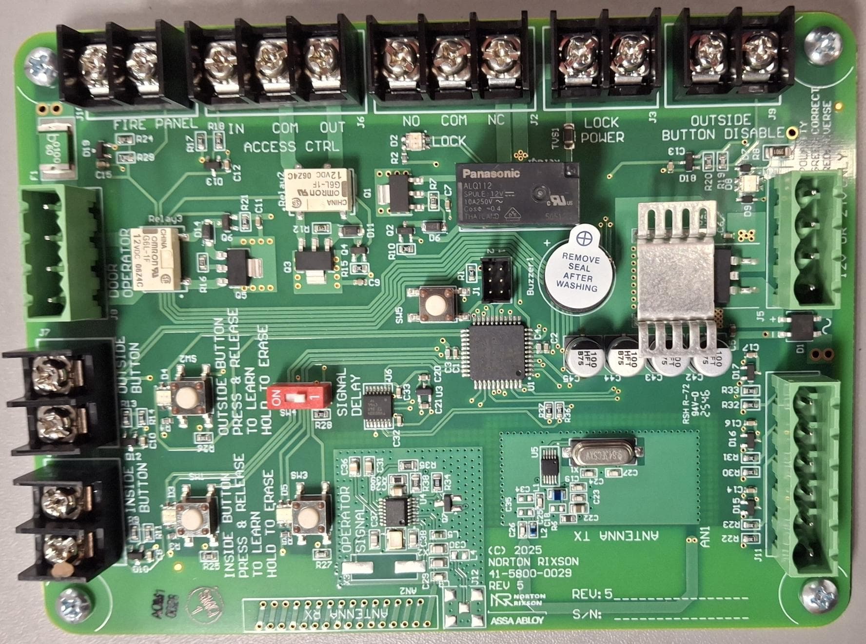
U4A-ADA1028W2
Aug 07, 2026Wireless Interface Device
Equipment Class
DSR - Part 15 Remote Control/Security Device Transceiver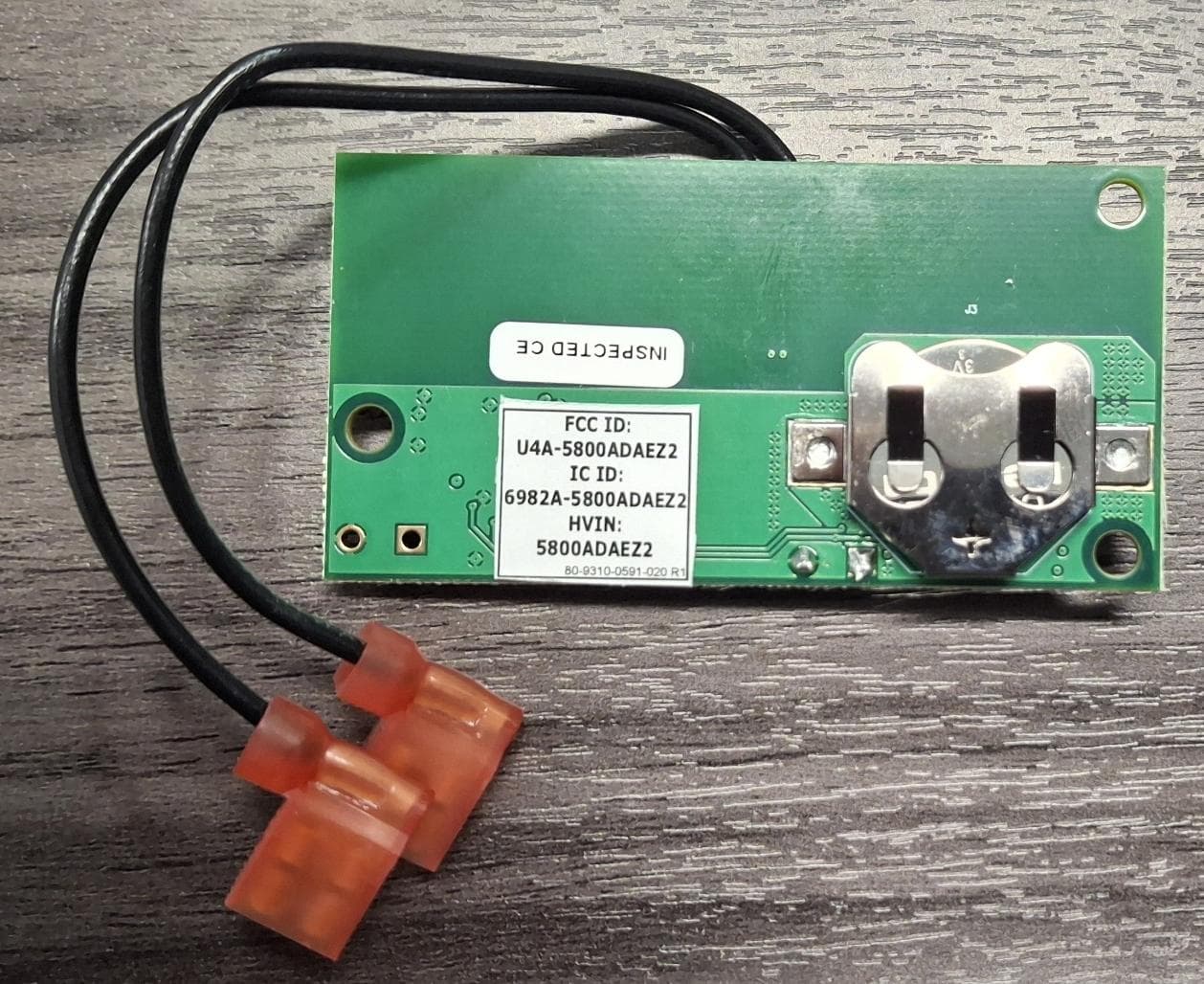
U4A5800ADAEZ2
Feb 20, 2026Wireless Interface Device
Equipment Class
DSR - Part 15 Remote Control/Security Device Transceiver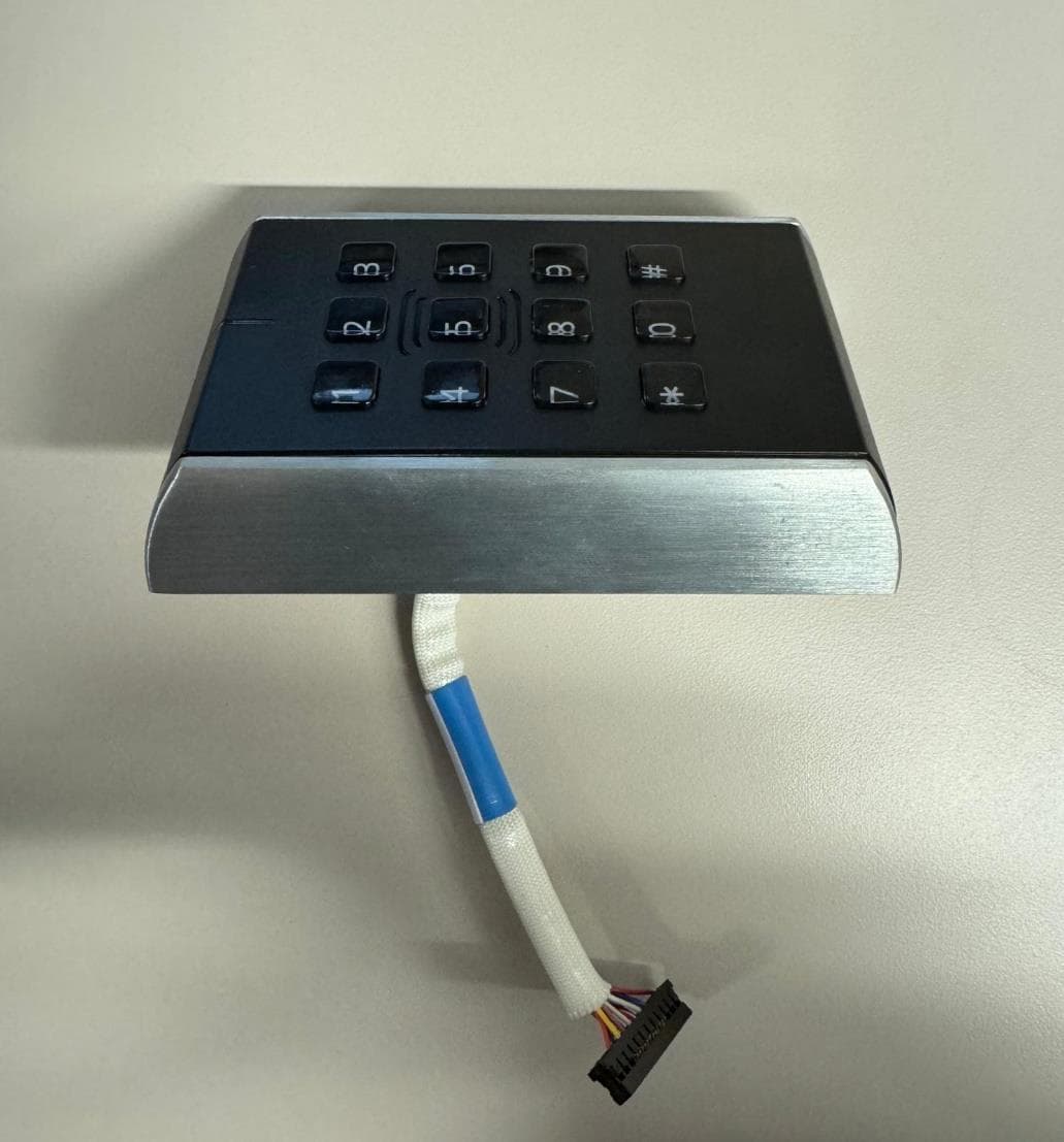
U4A-SCYMCA1K
Jul 28, 2024Aperio V3 IN100 Keypad Variant RF Module
Equipment Class
DXX - Part 15 Low Power Communication Device Transmitter
U4A-CEX100
Jun 05, 2023Access Control Lock
Equipment Class
DXX - Part 15 Low Power Communication Device Transmitter
U4A-YRHCPMT1FM
Mar 27, 2023Wireless Module to add BLE or Thread capabilities to Smart Door Locks
Equipment Class
DTS - Digital Transmission System