U4A-YRHCPZB0Yale Real Living Electronic Zigbee Lock
ASSA ABLOY Inc.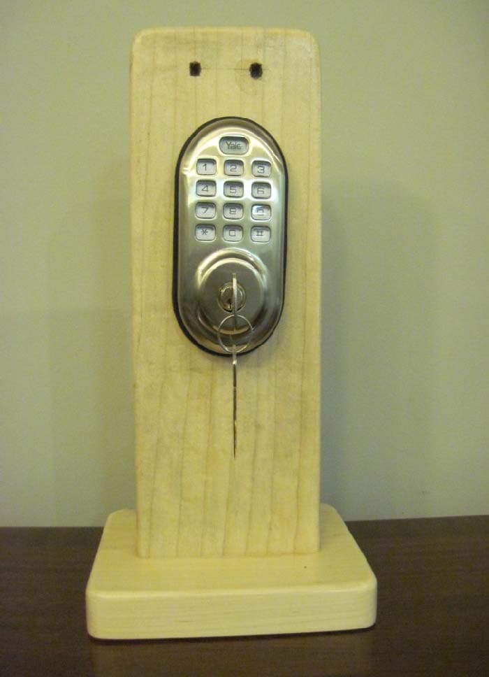
Click to zoom
Application Details
- Equipment Class
- DTS - Digital Transmission System
- Date of Grant
- May 19, 2011
- Application Purpose
- Original Equipment
- Date of Application
- May 18, 2011
- Equipment Note
- Yale Real Living Electronic Zigbee Lock
- Frequency Range
- 2405.00000000 - 2480.00000000
- Company
- ASSA ABLOY Inc.
- Country
- United States
Documents & Files
Document Text
Text extracted from the exhibit documents filed with the FCC. Open a document above to read the original.
Users Manual
Yale Real Living™ Touchscreen Deadbolt Installation and Programming Instructions For Technical Assistance call Yale at 1-800-810-WIRE (9473) NOTE TO INSTALLER FAILURE TO FOLLOW THESE INSTRUCTIONS COULD RESULT IN DAMAGE TO THE PRODUCT AND VOID THE FACTORY WARRANTY An ASSA ABLOY Group brand P/N AYRD220-INST-FUL Rev B This document is available on our website in printed Spanish and French. Go to www.yalerealliving.com. Click “Product Information & Documentation” and then “Installation Instructions”. Este documento está disponible en español en nuestra página de internet. Vaya a www.yalerealliving.com. Presione “Información del Producto y Documentación” y luego “Instrucciones de Instalación”. Ce document est disponible sur notre site Web dans le français imprimé. Allez à www.yalerealliving.com. Cliquez sur le “ ; Information sur le produit et Documentation” et puis “Installation Instructions”. 2 An ASSA ABLOY Group brand P/N AYRD220-INST-FUL Rev B Warnings .....................................................................................................................2-3 Introduction .....................................................................................................................3 Installation Components and Tools .............................................................................................4 Prepare Lock for Installation .....................................................................................5 Install Lock ............................................................................................................6-7 Programming Programming Features-Menu Keys-Definitions ...................................................8-9 Operation ..........................................................................................................10-12 Miscellaneous Information Return Lock to Programming Defaults ...................................................................13 Hardware Troubleshooting ......................................................................................13 Programming Troubleshooting ...............................................................................14 Replace/Install Cylinder ..........................................................................................15 Sample Pin Code Management Sheets ...........................................................16-17 TABLE OF CONTENTS WARNINGS FCC: FCC ID: U4A-YRHCPZW0 (Z-Wave); U4A-YRHCPZB0 (Zigbee) Model(s): YRDZW, YRDZB This equipment has been tested and found to comply with the limits for a Class B digital device, pursuant to Part 15 of the FCC Rules. These limits are designed to provide reasonable protection against harmful interference in a residential installation. This equipment generates, uses, and can radiate radio frequency energy and, if not installed and used in accordance with the instructions, may cause harmful interference to radio communications. However, there is no guarantee that interference will not occur in a particular installation. If this equipment does cause harmful Interference to radio or television reception, which can be determined by turning the equipment off and on, the user is encouraged to try to correct the interference by one or more of the following measures: • Reorient or relocate the receiving antenna. • Increase the separation between the equipment and receiver. • Connect the equipment into an outlet on a circuit different from that to which the receiver is connected. • Consult the dealer or an experienced radio/TV technician for help. IMPORTANT: The accuracy of the door preparation is critical for the proper functioning and security of this product. Misalignment can cause performance degradation and a lessening of security. Finish Care: This lockset is designed to provide the highest standard of product quality and performance. Care should be taken to ensure a long-lasting finish. When cleaning is required use a soft, damp cloth. Using lacquer thinner, caustic soaps, abrasive cleaners or polishes could damage the coating and result in tarnishing. Warning: Changes or modifications to this device not expressly approved by Yale Security, Inc. could void the user's authority to operate the equipment. 3 An ASSA ABLOY Group brand P/N AYRD220-INST-FUL Rev B INTRODUCTION The Yale Real Living™ Stand-alone Touchscreen Deadbolt Lock combines a robust lockset with a contemporary electronic aesthetic. Users benefit from an interactive touchscreen that makes day-to-day access effortless, as well as offering voice-guided programming for simple updates to user information in the event of staffing changes or security breaches. Yale Real Living™ is engineered for quick and easy installation and fits in place of a standard deadbolt lock door prep (ANSI/BHMA A156.115). If this is an RF-enabled network lock, it needs to be located within 50 - 100 feet of another network controller. That distance is influenced by objects between the lock and the controller and may be expanded depending on proximity to other RF network devices. Also, if the lock is connected to a network controller, it is recommended that it is programmed through the centralized user interface (PC or hand-held device) to ensure communication between the lock and the controller unit. Industry Canada: Canadian ID: 6982A-YRHCPZW0 (Z-Wave); 6982A-YRHCPZB0 (Zigbee) Model(s): YRDZW, YRDZB This Class B digital apparatus meets all requirements of the Canadian Interference Causing Equipment Regulations. Operation is subject to the following two conditions: (1) this device may not cause harmful interference, and (2) this device must accept any interference received, including interference that may cause undesired operation. Cet appareillage numérique de la classe B répond à toutes les exigences de l’interférence canadienne causant des règlements d’équipement. L’opération est sujette aux deux conditions suivantes: (1) ce dispositif peut ne pas causer l’interférence nocive, et (…
Text truncated - open the document above for the full version.
Cover Letter(s)
Americas Division 110 Sargent Drive New Haven, CT 06511 USA Phone: +1 203 821-5714 Fax: +1 203 603-5981 Email: [email protected] Steven Pfalzgraf Applications Engineer Authority to Act as Agent Date: 4/17/2011 American Certification Body, Inc. 6731 Whittier Avenue Suite C110 McLean, VA 22101 To Whom It May Concern: Thomas T. Smith, Ken Boston and Ryan Urness of LS Research, LLC is authorized to act on our behalf regarding product with FCC ID U4A-YRHCPZB0, until otherwise notified, for applications to American Certification Body, Inc. (ACB). We certify that we are not subject to denial of federal benefits, that includes FCC benefits, pursuant to Section 5301 of the Anti-Drug Abuse Act of 1988, 21 U.S.C. 862. Further, no party, as defined in 47 CFR 1.2002 (b), to the application is subject to denial of federal benefits, that includes FCC benefits. Thank you, Agency Agreement Expiration Date: 4/1/2012 By: Steven Pfalzgraf Title: Applications Engineer On behalf of: ASSA ABLOY
Cover Letter(s)
Americas Division 110 Sargent Drive New Haven, CT 06511 USA Phone: +1 203 821-5714 Fax: +1 203 603-5981 Email: [email protected] Steven Pfalzgraf Applications Engineer April 15, 2011 Federal Communications Commission Equipment Authorization Branch 7435 Oakland Mills Road Columbia, MD 21046 Subject: Confidentiality request for FCC ID: U4A-YRHCPZB0 equipment authorization application documentation. To Whom It May Concern, Pursuant to FCC regulations 0.459, ASSA ABLOY Inc. is respectfully requesting permanent confidential treatment of the following information accompanying this application: Block Diagrams Schematics Bill of Materials Theory of Operation The above materials contain trade secrets and proprietary information not customarily released to the public. The public disclosure of these matters might be harmful to the applicant and provide unjustified benefits to its competitors. Sincerely, Steven Pfalsgraf Applications Engineer ASSA ABLOY, Inc. 110 Sargent Drive New Haven, CT 06511
External Photos
EXTERNAL PHOTOS Company Name Assa Abloy, Inc. Model # YRDZB FCC ID # U4A‐YRHCPZB0 IC # 6982A‐YRHCPZB0 Page 1 of 3 Lock with key pad and physical key shown EXTERNAL PHOTOS Company Name Assa Abloy, Inc. Model # YRDZB FCC ID # U4A‐YRHCPZB0 IC # 6982A‐YRHCPZB0 Page 2 of 3 Lock shown with battery compartment on and latch exemplified Programming cable attached to the radio is shown EXTERNAL PHOTOS Company Name Assa Abloy, Inc. Model # YRDZB FCC ID # U4A‐YRHCPZB0 IC # 6982A‐YRHCPZB0 Page 3 of 3 Battery cover removed, exhibiting the battery cover and the radio and antenna
ID Label/Location Info
YRDZB Label material is white art paper sticker Batter cover is retained by screw on product Model YRDZBModel YRDZB
Internal Photos
INTERNAL PHOTOS Company Name Assa Abloy Model # YRDZB FCC ID # U4A‐YRHCPZB0 IC # 6982A‐YRHCPZB0 Page 1 of 3 Inverted‐F PCB antenna shown Attachment of the PCB antenna to the radio board INTERNAL PHOTOS Company Name Assa Abloy Model # YRDZB FCC ID # U4A‐YRHCPZB0 IC # 6982A‐YRHCPZB0 Page 2 of 3 The top of the radio board (with respect to the position of the board in the housing) The bottom of the radio board (with respect to the position of the board in the housing). 8‐pin connector shown which is the only physical connection from the radio board to the lock. INTERNAL PHOTOS Company Name Assa Abloy Model # YRDZB FCC ID # U4A‐YRHCPZB0 IC # 6982A‐YRHCPZB0 Page 3 of 3 The bottom of the radio board (with respect to the position of the board in the housing).
RF Exposure Info
MPE CALCULATIONS The following MPE calculations are based on a inverted-F PCB board trace antenna, with a measured ERP of 91.9 dBμV/m, at 3 meters, and conducted RF power of +3.6 dBm as presented to the antenna. The calculated gain of this antenna, based on the ERP measurements is -6.93 dB. Prediction of MPE limit at a given distance Equation from page 18 of OET Bulletin 65, Edition 97-01 where:S = power density P = power input to the antenna G = power gain of the antenna in the direction of interest relative to an isotropic radiator R = distance to the center of radiation of the antenna Maximum peak output power at antenna input terminal:3.60(dBm) Maximum peak output power at antenna input terminal:2.291(mW) Antenna gain(typical):-6.93(dBi) Maximum antenna gain:0.203(numeric) Prediction distance:20(cm) Prediction frequency:2480(MHz) MPE limit for uncontrolled exposure at prediction frequency:1(mW/cm^2) Power density at prediction frequency:0.000092(mW/cm^2) Maximum allowable antenna gain:33.4(dBi) 20cm =40.3dBMargin of Compliance at 2 4R PG S p =
Test Report
W66 N220 Commerce Court ● Cedarburg, WI 53012 ● USA Phone: 262.375.4400 ● Fax: 262.375.4248 www.lsr.com TEST REPORT # Q310378 LSR Job #: C-1177 Compliance Testing of: Yale Real Living Deadbolt Test Date(s): April 6, 18, 20, 26, 2011 Prepared For: ASSA Abloy Attn: Mark Caterino 100 Sargent Drive New Haven, CT 06511 In accordance with: Federal Communications Commission (FCC) Part 15, Subpart C, Section 15.247 Industry Canada (IC) RSS 210 Digital Modulation Transmitters (DTS) Operating in the Frequency Band 2400 MHz – 2483.5 MHz This Test Report is issued under the Authority of: Thomas T. Smith Signature: Date: 05.11.11 Test Report Reviewed by: Thomas T. Smith Signature: Date: 05.11.11 Tested by: Peter Feilen, EMC Engineer Signature: Date: 05.11.11 Shane Rismeyer, EMC Engineer Signature: Date: 05.11.11 This Test Report may not be reproduced, except in full, without written approval of LS Research, LLC. Prepared For: Assa Abloy EUT: Yale Real Living Deadbolt LS Research, LLC Report # 310378 Model #: YDRZB Template: 15.109 Class B DTS 10-22-09 LSR Job #: C-1177 Serial #: N/A Page 2 of 45 TABLE OF CONTENTS (page 1 of 2) EXHIBIT 1: INTRODUCTION 1.1 Scope 4 1.2 Normative References 4 1.3 LS Research, LLC Test Facility 5 1.4 Location of Testing 5 1.5 Test Equipment Utilized 5 EXHIBIT 2: PERFORMANCE ASSESSMENT 2.1 Client Information 6 2.2 Equipment Under Test (EUT) Information 6 2.3 Associated Antenna Description 6 2.4 EUT’s Technical Specifications 7 2.5 Product Description 8 EXHIBIT 3: EUT OPERATING CONDITIONS & CONFIGURATIONS DURING TESTS 3.1 Climate Test Conditions 9 3.2 Applicability & Summary of EMC Emission Test Results 9 3.3 Modifications Incorporated in the EUT for Compliance Purposes 9 3.4 Deviations & Exclusions from Test Specifications 9 EXHIBIT 4: DECLARATION OF CONFORMITY 10 EXHIBIT 5: RADIATED EMISSIONS TESTING Note: Items 5.1 through 5.8 are for TRANSMIT MODE Item 5.9 is for RECEIVE MODE 5.1 Test Setup 11 5.2 Test Procedure 11 5.3 Test Equipment Utilized 12 5.4 Test Results 12 5.5 Calculation of Radiated Emissions Limits 13 5.6 Radiated Emissions Test Data Chart 14 5.7 Test Setup Photo(s) – Radiated Emissions Test 17 5.8 Receive Mode Testing 21 EXHIBIT 6: OCCUPIED BANDWIDTH 6.1 Limits 25 6.2 Method of Measurements 25 6.3 Test Equipment List 25 6.4 Test Data 25 6.5 Screen Captures – Occupied Bandwidth 26 EXHIBIT 7: BAND-EDGE MEASUREMENTS 7.1 Method of Measurements 29 7.2 Screen Captures 29 Prepared For: Assa Abloy EUT: Yale Real Living Deadbolt LS Research, LLC Report # 310378 Model #: YDRZB Template: 15.109 Class B DTS 10-22-09 LSR Job #: C-1177 Serial #: N/A Page 3 of 45 EXHIBIT 8: POWER OUTPUT (CONDUCTED): 15.247(b) 8.1 Method of Measurements 31 8.2 Test Equipment List 31 8.3 Test Data 31 8.4 Screen Captures – Power Output (Conducted) 31 EXHIBIT 9: POWER SPECTRAL DENSITY: 15.247(e) 9.1 Limits 34 9.2 Test Equipment List 34 9.3 Test Data 34 9.4 Screen Captures – Power Spectral Density 35 EXHIBIT 10: SPURIOUS RADIATED EMISSIONS: 15.247(d) 10.1 Limits 37 10.2 Test Equipment List 38 10.3 Test Data 38 10.4 Screen Captures – Spurious Radiated Emissions 39 EXHIBIT 11: FREQUENCY AND POWER STABILITY OVER VOLTAGE VARIATION 41 APPENDICES APPENDIX A: TEST EQUIPMENT LIST 42 APPENDIX B: TEST STANDARDS – RADIO 44 APPENDIX C: UNCERTAINTY STATEMENT 45 Prepared For: Assa Abloy EUT: Yale Real Living Deadbolt LS Research, LLC Report # 310378 Model #: YDRZB Template: 15.109 Class B DTS 10-22-09 LSR Job #: C-1177 Serial #: N/A Page 4 of 45 EXHIBIT 1. INTRODUCTION 1.1 SCOPE References: FCC Part 15, Subpart C, Section 15.247 and 15.209 FCC Part 2, Section 2.1043 paragraph (b)1. RSS GEN and RSS 210 Annex 8 Title: FCC : Telecommunication – Code of Federal Regulations, CFR 47, Part 15. IC : Low-power License-exempt Radio-communication Devices (All Frequency Bands): Category I Equipment Purpose of Test: To gain FCC and IC Certification Authorization for Low- Power License-Exempt Transmitters. Test Procedures: Both conducted and radiated emissions measurements were conducted in accordance with American National Standards Institute ANSI C63.4 – American National Standard for Methods of Measurement of Radio-Noise Emissions from Low-Voltage Electrical and Electronic Equipment in the Range of 9 kHz to 40 GHz. Environmental Classification: Commercial, Industrial or Business Residential 1.2 NORMATIVE REFERENCES Publication Year Title 47 CFR, Parts 0-15 (FCC) 2008 Oct Code of Federal Regulations - Telecommunications RSS 210 Annex 8 2010 Dec Low-power License-exempt Radio-communication Devices (All Frequency Bands): Category I Equipment ANSI C63.4 2003 American National Standard for Methods of Measurement of Radio-Noise Emissions from Low-Voltage Electrical and Electronic Equipment in the Range of 9 kHz to 40 GHz. CISPR 16-1-1 2006-03 A1: 2006-09 A2: 2007-07 Specification for radio disturbance and immunity measuring apparatus and methods. Part 1-1: Measuring Apparatus. CISPR 16-2-1 2003 A1: 2004-04 A2: 2007-07 Specification for radio disturbance and immunity measuring apparatus and methods. Part 201: Conducted disturbance measurement. FCC Public Notice DA 00-1407 2000 Part 15 Unlicensed Modular Transmitter Approval FCC ET Docket No. 99-231 2002 Amendment to FCC Part 15 of the Commission’s Rules Regarding Spread Spectrum Devices. FCC Procedures 2007 Measurement of Digital Transmission Systems operating under Section 15.247. Prepared For: Assa Abloy EUT: Yale Real Living Deadbolt LS Research, LLC Report # 310378 Model #: YDRZB Template: 15.109 Class B DTS 10-22-09 LSR Job #: C-1177 Serial #: N/A Page 5 of 45 1.3 LS Research, LLC TEST FACILITY LS Research, LLC is accredited by A2LA (American Association for Laboratory Accreditation) to conform to ISO/IEC 17025, 2005 “General Requirements for the Competence of Calibration and Testing Laboratories”. LS Research, LLC’s scope of accreditation includes all test methods listed herein, unless otherwise noted. A copy of the accreditation may be accessed on our web site: www…
Text truncated - open the document above for the full version.
Test Setup Photos
TEST SETUP PHOTOS Company Name Assa Abloy Model # YRDZB FCC ID # U4A‐YRHCPZB0 IC # 6982A‐YRHCPZB0 Page 1 of 3 3m Measurement Setup TEST SETUP PHOTOS Company Name Assa Abloy Model # YRDZB FCC ID # U4A‐YRHCPZB0 IC # 6982A‐YRHCPZB0 Page 2 of 3 TEST SETUP PHOTOS Company Name Assa Abloy Model # YRDZB FCC ID # U4A‐YRHCPZB0 IC # 6982A‐YRHCPZB0 Page 3 of 3 1m measurement setup
Contact Information
Applicant
James Forte(Senior Product Compliance Engineer)
Technical Contact
Assa Abloy Inc.Mark Caterino
[email protected]203-498-5588
110 Sargent Drive · New Haven, Connecticut · United States
Test Firm
LS Research, LLCRyan Urness
Technical Specifications
| # | Rule Parts | Frequency Range | Power Output |
|---|---|---|---|
| 1 | 15C | 2.40 GHz - 2.48 GHz | 464.50 µW |
Other Applications from ASSA ABLOY Inc.
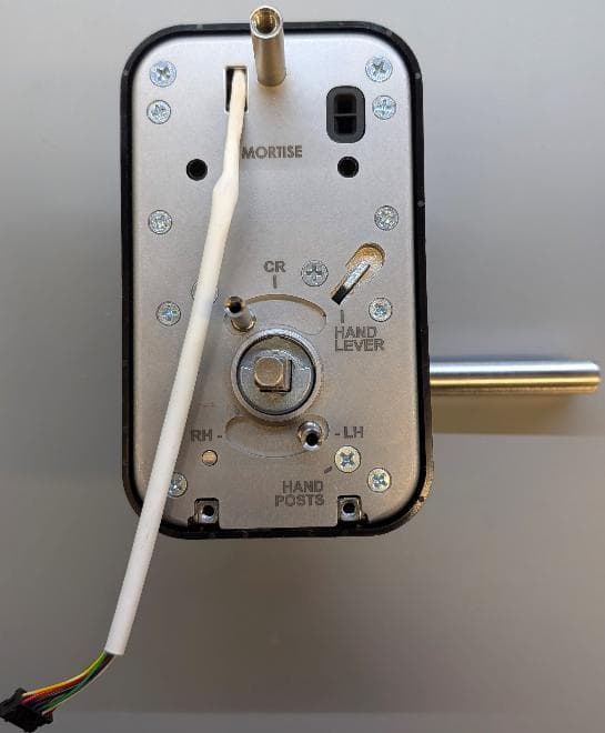
U4A-LNK100
Sep 03, 2026Real-Time Wireless Locks
Equipment Class
DTS - Digital Transmission System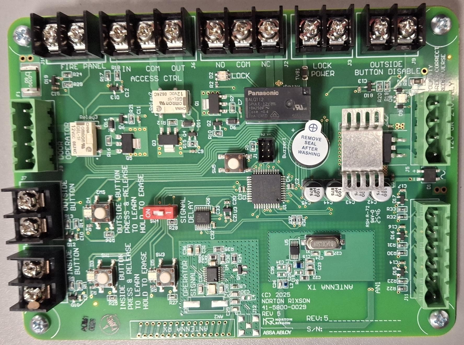
U4A-ADA1028W2
Aug 07, 2026Wireless Interface Device
Equipment Class
DSR - Part 15 Remote Control/Security Device Transceiver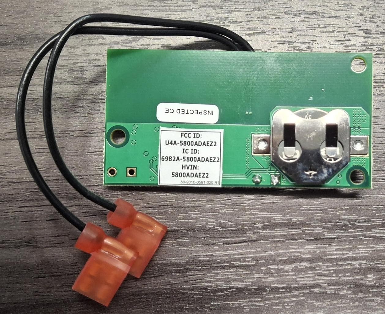
U4A5800ADAEZ2
Feb 20, 2026Wireless Interface Device
Equipment Class
DSR - Part 15 Remote Control/Security Device Transceiver
U4A-SCYMCA1K
Jul 28, 2024Aperio V3 IN100 Keypad Variant RF Module
Equipment Class
DXX - Part 15 Low Power Communication Device Transmitter
U4A-CEX100
Jun 05, 2023Access Control Lock
Equipment Class
DXX - Part 15 Low Power Communication Device Transmitter