U4A-YRHCPZB0FMZigbee Transceiver Module
ASSA ABLOY Inc.
Click to zoom
Application Details
- Equipment Class
- DTS - Digital Transmission System
- Date of Grant
- Jun 09, 2015
- Application Purpose
- Original Equipment
- Date of Application
- Jun 08, 2015
- Equipment Note
- Zigbee Transceiver Module
- Frequency Range
- 2405.00000000 - 2475.00000000
- Company
- ASSA ABLOY Inc.
- Country
- United States
Documents & Files
Document Text
Text extracted from the exhibit documents filed with the FCC. Open a document above to read the original.
Users Manual
® Yale Real Living™ ZigBee Module Installation and Programming Instructions ® Installing the ZigBee Module It is recommended that lock is programmed through the centralized user interface (PC or hand-held device) to ensure communication between the lock and the controller unit. The network controller first needs to be in enrollment or exclusion mode for the lock to be enrolled or unenrolled from network. To Enroll the Module: • Enter the 4-8 digit Master PIN code followed by the key. • Press the key followed by the key. • Press the key followed by the key. To Unenroll the Module: • Enter the 4-8 digit Master PIN code followed by the key. • Press the key followed by the key. • Press the key followed by the key. Enrolling/Unenrolling the Network Module: IMPORTANT: the batteries must be removed prior to removing and/or inserting the network module: • Remove battery cover. • Remove batteries. • Remove and/or insert network module. • Reinstall batteries. • Replace cover. P/N AYR200-ZB-INSTAL-FUL Rev E FCC: FCC ID: UA4-YRHCPZB0FM Model: YRMZB2 This equipment has been tested and found to comply with the limits for a Class B digital device, pursuant to Part 15 of the FCC Rules. These limits are designed to provide reasonable protection against harmful interference in a residential installation. This equipment generates, uses, and can radiate radio frequency energy and, if not installed and used in accordance with the instructions, may cause harmful interference to radio communications. However, there is no guarantee that interference will not occur in a particular installation. If this equipment does cause harmful Interference to radio or television reception, which can be determined by turning the equipment off and on, the user is encouraged to try to correct the interference by one or more of the following measures: Reorient or relocate the receiving antenna. Increase the separation between the equipment and receiver. Connect the equipment into an outlet on a circuit different from that to which the receiver is connected. Consult the dealer or an experienced radio/TV technician for help. This equipment complies with FCC radiation exposure limits set forth for an uncontrolled environment. This equipment should be installed and operated with minimum distance 20cm between the radiator and your body. This transmitter must not be co-located or operating in conjunction with any other antenna or transmitter. This device complies with Part 15 of the FCC rules. Operation is subject to the following two conditions: (1) This device may not cause harmful interference, and (2) this device must accept any interference received, including interference that may cause undesired operation. Any changes or modifications not expressly approved by manufacturer could void the user’s authority to operate the equipment. IMPORTANT! Any changes or modifications not expressly approved by the party responsible for compliance could void the user’s authority to operate this equipment. Industry Canada: IC: 6982A-YRHCPZB0FM Model: YRMZB2 Section 8.4 of RSS-GEN This Device complies with Industry Canada License-exempt RSS standard(s). Operation is subject to the following two conditions: 1) this device may not cause interference, and 2) this device must accept any interference, including interference that may cause undesired operation of the device. Le présent appareil est conforme aux CNR d'Industrie Canada applicables aux appareils radio exempts de licence. L'exploitation est autorisée aux deux conditions suivantes: (1) l'appareil ne doit pas produire de brouillage, et (2) l'utilisateur de l'appareil doit accepter tout brouillage radioélectrique subi, meme si le brouillage est susceptible d'en compromettre le fonctionnement. Important Note: Radiation Exposure Statement: This equipment complies with IC radiation exposure limits set forth for an uncontrolled environment. This equipment should be installed and operated with minimum distance 20cm between the radiator and your body. Note Importante: (Pour l’utilisation de dispositifs mobiles) Declaration d’exposition aus radiations: Cet équipement est conforme aux limites d ́exposition aux rayonnements IC établies pour un environnement non contrôlé. Cet équipment doit être installé et utilisé avec un mimimum de 20 cm de distance entre la source de rayonnement et votre corps. IMPORTANT! Any changes or modifications not expressly approved by the party responsible for compliance could void the user’s authority to operate this equipment. IMPORTANT! Tous les changements ou modifications pas expressément approuvés par la partie responsable de la conformité ont pu vider l’autorité de l’utilisateur pour actioner cet équipment. Product Support Tel 800.810.WIRE (9473) • www.yalelocks.com Yale® is a registered trademark of Yale Security Inc., an ASSA ABLOY Group company. Yale Real Living™ is a trademark of Yale Security Inc., an ASSA ABLOY Group company. Copyright © 2015, Yale Security Inc., an ASSA ABLOY Group company. All rights reserved. Reproduction in whole or in part without the express written permission of Yale Security Inc. is prohibited. Yale Locks & Hardware is a division of Yale Security Inc., an ASSA ABLOY Group company. YALE, with its unique global reach and range of products, is the world's favorite lock – the preferred solution for securing your home, family and personal belongings. ASSA ABLOY is the global leader in door opening solutions, dedicated to satisfying end-user needs for security, safety and convenience.
Cover Letter(s)
Americas Division 110 Sargent Drive New Haven, CT 06511 USA Phone: +1 203 821-5714 Fax: +1 203 603-5981 Email: [email protected] Steven Pfalzgraf EM Product Engineer March 3, 2015 Nemko Canada Inc 303 River Road Ottawa, Ontario, Canada K1V 1H2 Attn: Director of Certification Authority to Act as Agent On our behalf, I appoint Erin Allred of Nemko-CCL, Inc. at 1940 W. Alexander Street, Salt Lake City, UT 84119 to act as our agent in the preparation of this application for equipment certification. I certify that submitted documents properly describe the device or system for which equipment certification is sought. I also certify that each unit manufactured, imported or marketed, as defined in the Federal Communications Commission’s regulations will have affixed to it a label identical to that submitted for approval with this application. For instances where our authorized agent signs the application for certification on our behalf, I acknowledge that all responsibility for complying with the terms and conditions for certification, as specified by Nemko Canada Inc, still resides with Assa Abloy Inc. 110 Sargent Drive, New Haven, CT, 06511, USA. Dated this 3rd Day of March 20 15 Agency agreement expiration date: December 31, 2015 By: Steven Pfalzgraf Signature Printed Title: EM Product Engineer On behalf of : Assa Abloy Inc. Telephone: +1 203 821-5714
Cover Letter(s)
Americas Division 110 Sargent Drive New Haven, CT 06511 USA Phone: +1 203 821-5714 Fax: +1 203 603-5981 Email: [email protected] Steven Pfalzgraf EM Product Engineer March 3, 2015 Federal Communications Commission Authorization and Evaluation Division Confidentiality Request regarding application for certification of FCC ID: U4A-YRHCPZB0FM. Pursuant to Sections 0.457 and 0.459 of the Commission’s Rules, we hereby request confidential treatment of information accompanying this application as outlined below: Exhibit Type Block Diagram Schematics Operational Description Parts List The above materials contain trade secrets and proprietary information not customarily released to the public. The public disclosure of these materials may be harmful to the applicant and provide unjustified benefits to its competitors. The applicant understands that pursuant to Section 0.457 of the Rules, disclosure of this application and all accompanying documentation will not be made before the date of the Grant for this application. Signed: Name: Steven Pfalzgraf Title: EM Product Engineer
Cover Letter(s)
Americas Division 110 Sargent Drive New Haven, CT 06511 USA Phone: +1 203 821-5714 Fax: +1 203 603-5981 Email: [email protected] Steven Pfalzgraf Applications Engineer Modular Approval Request Applicant: Assa Abloy Inc. FCC ID: U4A-YRHCPZB0FM Date:4/20/2015 To Whom IT May Concern: Pursuant to Section 15.212(a) (1) of the FCC rules, the Applicant hereby requests for modular approval, compliance with the requirements are addressed below. Modular Approval Requirements Justification i. The radio elements must have the radio frequency circuitry shielded. Physical components and tuning capacitor(s) may be located external to the shield, but must be on the module assembly; All radio elements are properly shielded. ii. The module must have buffered modulation/data inputs to ensure that the device will comply with Part 15 requirements with any type of input signal; The module does implement buffered modulation/data inputs iii. The module must contain power supply regulation on the module; The module has its own power supply regulation iv. The module must contain a permanently attached antenna, or contain a unique antenna connector, and be marketed and operated only with specific antenna(s), per Sections 15.203, 15.204(b), 15.204(c), 15.212(a), 2.929(b); The antenna for the YRMZB2 is permanently attached to the module v. The module must demonstrate compliance in a stand-alone configuration; The module meets requirements for compliance in a stand-alone configuration vi. The module must be labelled with its permanently affixed FCC ID label, or use an electronic display; The module has a permanently affixed FCC ID label vii. The module must comply with all specific rules applicable to the transmitter including all the conditions provided in the integration instructions by the grantee; Instructions are provided to ensure proper installation of the module and to ensure it complies with all applicable rules and operating requirements. viii. The module must comply with RF exposure requirements; The module has been shown to comply with all applicable RF exposure requirements Sincerely, Steven Pfalzgraf Applications Engineer
Cover Letter(s)
Label Requirements Company: Assa Abloy, Inc. Brand Name: Yale Model Number: YRMZB2 FCC ID: U4A-YRHCPZB0FM The modules may be purchased separately. They will only work in Yale Real Living locks however, and the end user has the choice as to which module they decide to use with their lock (ZWave or ZigBee). In some instances the module will be installed at the factory. Other instances the module will be placed in the box and the end user will install it during installation of the lock. There is also the possibility of the end user purchasing a module separately to use with a Yale lock they may already have. End users have straightforward commonly used methods for access to remove the module such that the FCC ID of the module is visible.
Cover Letter(s)
ATT-001 Issue 1 March 2012 MANUFACTURER’S STATEMENT / ATTESTATION Applicant: Assa Abloy Inc. Address: 110 Sargent Drive, New Haven, CT 06511 USA Contact Name: Steven Pfalzgraf Title: EM Product Engineer Brand Name: Yale Model Number: YRMZB2 FCC ID / IC ID: U4A-YRHCPZB0FM / 6982A-YRHCPZB0FM Nemko-CCL Test Report: 278528-6.3 and 278528-8.4. The manufacturer or responsible party for the equipment tested hereby affirms: a) That he/she has reviewed and concurs that the tests shown in this report are reflective of the operational characteristics of the device for which certification is sought; b) That the device in this test report will be representative of production units; c) That the product will have all of the documented modifications incorporated into the product when manufactured and placed on the market; d) That all changes in hardware and software/firmware to the subject device will be reviewed. e) That any changes impacting the attributes, functionality or operational characteristics documented in this report will be communicated to the body responsible for approving or certifying the subject equipment. Steven Pfalzgraf 3/6/2015 Authorized Representative (please print) Signature Date
External Photos
External Photographs Top View of the EUT Bottom View of the EUT
Internal Photos
Internal Photographs View of the Top of the PCB with Shielding View of the Top of the PCB with Shielding Removed View of the Bottom of the PCB with Shielding View of the Bottom of the PCB with Shielding Removed
RF Exposure Info
Nemko-CCL, Inc. 1940 West Alexander Street Salt Lake City, Utah 84119-2039 Maximum Permissible Exposure (MPE) Requirement Applicant: Assa Abloy Inc Job Number / NEX # 278528 Model No.: YRMZB2 This document was prepared in by Nemko-CCL on behalf of the applicant using data collected during testing and information provided by the applicant. The maximum power density requirements for the General Public (Uncontrolled Environment) listed in FCC Part 1.1310 were used. The power density is calculated using the following equation. ܲ ௗ ൌ ܲ ௧ ܩ ∗ - ݎߨ4 ଶ P d = power density in watts P t = transmit power in milliwatts G = numeric antenna gain r = distance between body and transmitter in centimeters ∗ ܲ ௧ ܩ = EIRP The calculated power density of the EUT listed in this application is calculated below. Max Transmit Power EIRP (mW): 1.1858E+02 Max Antenna Gain (dBi): 0 O perating Frequency (MHz): 2440 (Numeric Antenna Gain): 1.00 Min Operating Distance (cm): 20 Duty Cycle (%): 100 P ower Density (mW/cm 2 ):2.36E-02 Limit (mW/cm 2 ):1.00E+00 Delta:-9.76E-01
Test Report
Nemko-CCL, Inc. 1940 West Alexander Street Salt Lake City, UT 84119 801-972-6146 Test Report Certification Test Of: YRMZB2 FCC ID: U4A-YRHCPZB0FM Test Specifications: FCC PART 15, Subpart C Test Report Serial No: 278528-6.3 Applicant: Assa Abloy Inc. 110 Sargent Drive New Haven, CT 06511 U.S.A Dates of Test: January 20 – 21, 2015 Report Issue Date: February 10, 2015 Accredited Testing Laboratory By: NVLAP Lab Code 100272-0 Nemko-CCL, Inc. TEST REPORT: 278528-6.3 REPORT ISSUE DATE: 02/10/2015 Page 2 of 57 TRF-15.247 DTS SUBC Issue 2 Jan. 2015 CERTIFICATION OF ENGINEERING REPORT This report has been prepared by Nemko-CCL, Inc. to document compliance of the device described below with the requirements of Federal Communications Commission (FCC) Part 15, Subpart C. This report may be reproduced in full, partial reproduction may only be made with the written consent of the laboratory. The results in this report apply only to the sample tested. - Applicant: Assa Abloy Inc. - Manufacturer: Assa Abloy Inc. - Brand Name: Yale - Model Number: YRMZB2 - FCC ID: U4A-YRHCPZB0FM On this 10 th day of February 2015, I, individually and for Nemko-CCL, Inc., certify that the statements made in this engineering report are true, complete, and correct to the best of my knowledge, and are made in good faith. Although NVLAP has recognized that the Nemko-CCL, Inc. EMC testing facilities are in good standing, this report must not be used to claim product certification, approval, or endorsement by NVLAP, NIST, or any agency of the federal government. Nemko-CCL, Inc. Tested by: Norman P. Hansen Test Technician Reviewed by: Mark M. Feil EMC Engineer Nemko-CCL, Inc. TEST REPORT: 278528-6.3 REPORT ISSUE DATE: 02/10/2015 Page 3 of 57 TRF-15.247 DTS SUBC Issue 2 Jan. 2015 TABLE OF CONTENTS PAGE SECTION 1.0 CLIENT INFORMATION .................................................................................4 SECTION 2.0 EQUIPMENT UNDER TEST (EUT)..................................................................5 SECTION 3.0 TEST SPECIFICATION, METHODS & PROCEDURES .............................7 SECTION 4.0 OPERATION OF EUT DURING TESTING..................................................13 SECTION 5.0 SUMMARY OF TEST RESULTS ...................................................................14 SECTION 6.0 MEASUREMENTS AND RESULTS ...............................................................15 APPENDIX 1 TEST PROCEDURES AND TEST EQUIPMENT .........................................42 APPENDIX 2 PHOTOGRAPHS ................................................................................................47 Nemko-CCL, Inc. TEST REPORT: 278528-6.3 REPORT ISSUE DATE: 02/10/2015 Page 4 of 57 TRF-15.247 DTS SUBC Issue 2 Jan. 2015 SECTION 1.0 CLIENT INFORMATION 1.1 Applicant: Company Name: Assa Abloy Inc. 110 Sargent Drive New Haven, CT 06511 U.S.A Contact Name: Steven Pfalzgraf Title: EM Product Engineer 1.2 Manufacturer: Company Name: Assa Abloy Inc. 110 Sargent Drive New Haven, CT 06511 U.S.A Contact Name: Steven Pfalzgraf Title: EM Product Engineer Nemko-CCL, Inc. TEST REPORT: 278528-6.3 REPORT ISSUE DATE: 02/10/2015 Page 5 of 57 TRF-15.247 DTS SUBC Issue 2 Jan. 2015 SECTION 2.0 EQUIPMENT UNDER TEST (EUT) 2.1 Identification of EUT: Brand Name: Yale Model Number: YRMZB2 Serial Number: None Dimensions: 5.5 cm x 2.6 cm x 1.0 cm 2.2 Description of EUT: The YRMZB2 is a transceiver module operating at 2.4 GHz that can interface a home automation/control system. The YRMZB2 typically is installed in a door lock assembly and interfaces an 8 pin header. 6 Vdc to power the YRMZB2 comes from the 4 AA batteries of the lock assembly. For testing conducted emissions at the AC mains as required for modules, an Anome Electric Co. LTD AEC-4850 AC to DC adapter was connected to the power pins of the YRMZB2. The 2.4 GHz transceiver operates using 15 channels with the frequency assignments shown in the table below. The antenna is an inverted F-type trace antenna with a maximum gain of 3.3 dBi. Channel Frequency (MHz) Channel Frequency (MHz) Channel Frequency (MHz) Channel Frequency (MHz) 11 2405 15 2425 19 2445 23 2465 12 2410 16 2430 20 2450 24 2470 13 2415 17 2435 21 2455 25 2475 14 2420 18 2440 22 2460 This report covers the circuitry of the devices subject to FCC Part 15, Subpart C. The circuitry of the device subject to FCC Subpart B was found to be compliant and is covered in Nemko-CCL, Inc. report 278528-1. 2.3 EUT and Support Equipment: The FCC ID numbers for all the EUT and support equipment used during the test are listed below: Brand Name Model Number Serial Number FCC ID Number or Compliance Description Name of Interface Ports / Interface Cables BN: Yale MN: YRMZB2 (Note 1) SN: None U4A- YRHCPZB0FM 2.4 GHz transceiver module See Section 2.4 Note: (1) EUT Nemko-CCL, Inc. TEST REPORT: 278528-6.3 REPORT ISSUE DATE: 02/10/2015 Page 6 of 57 TRF-15.247 DTS SUBC Issue 2 Jan. 2015 2.4 Interface Ports on EUT: Name of Ports No. of Ports Fitted to EUT Cable Descriptions/Length Lock interface with power 1 8 pin header for direct connection to lock assembly (For testing, 10 cm conductors were attached and extended to 4 AA batteries and for connection to a computer for controlling the transceiver) 2.5 Modification Incorporated/Special Accessories on EUT: The following modifications were made to the EUT by the Client during testing to comply with the specification. This report is not complete without an accompanying signed attestation, that the product will have all of the documented modifications incorporated into the product when manufactured and placed on the market. 1. In order to comply with the emissions in the restricted bands, the maximum power settings had to be reduced from 0 (Hexadecimal). The maximum transmitter power setting was reduced to -4 (Hexadecimal) when using channels 11 – 23. Channel 24 maximum power setting was reduced to -9 (Hexadecimal). Channel 25 maximum power setting was reduced to –F (Hexadecimal). In production firmware, th…
Text truncated - open the document above for the full version.
Test Setup Photos
Setup Photographs Front View Radiated Disturbance Worst Case Configuration – Horizontal Front View Radiated Disturbance Configuration – On Edge Front View Radiated Disturbance Configuration – Vertical Front View Conducted Disturbance Worst Case Configuration Back View Conducted Disturbance Worst Case Configuration
Contact Information
Applicant
James Forte(Senior Product Compliance Engineer)
Test Firm
Nemko-CCL incThomas Jackson
Technical Specifications
| # | Rule Parts | Frequency Range | Power Output |
|---|---|---|---|
| 1 | 15C | 2.40 GHz - 2.48 GHz | 55.00 mW |
Other Applications from ASSA ABLOY Inc.
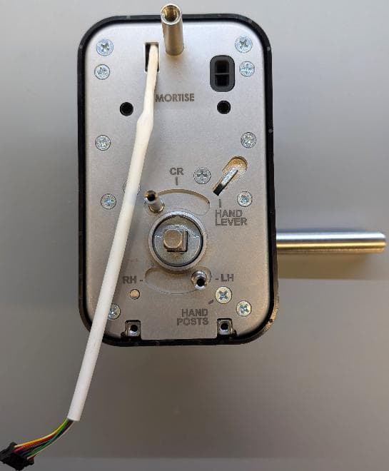
U4A-LNK100
Sep 03, 2026Real-Time Wireless Locks
Equipment Class
DTS - Digital Transmission System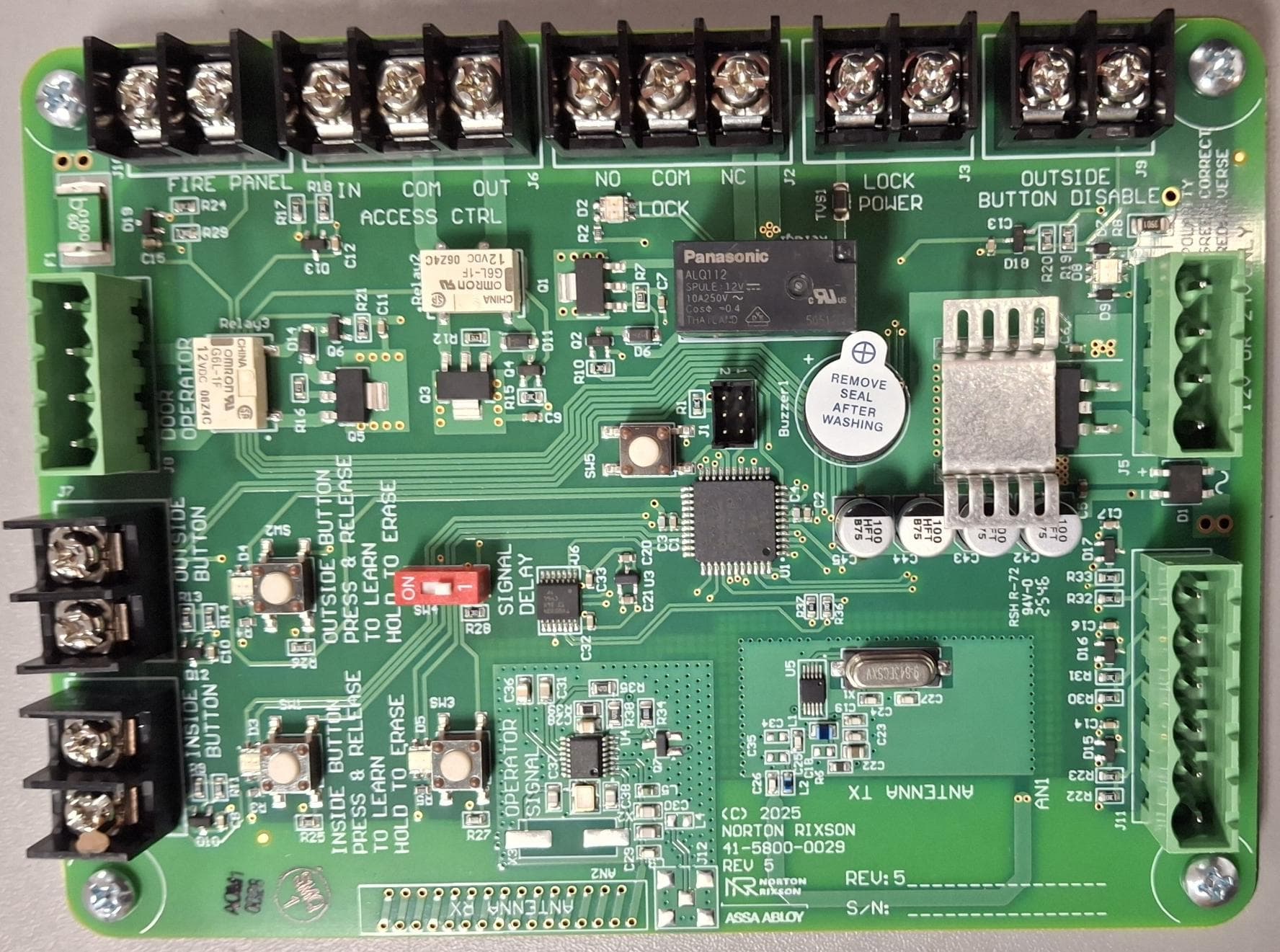
U4A-ADA1028W2
Aug 07, 2026Wireless Interface Device
Equipment Class
DSR - Part 15 Remote Control/Security Device Transceiver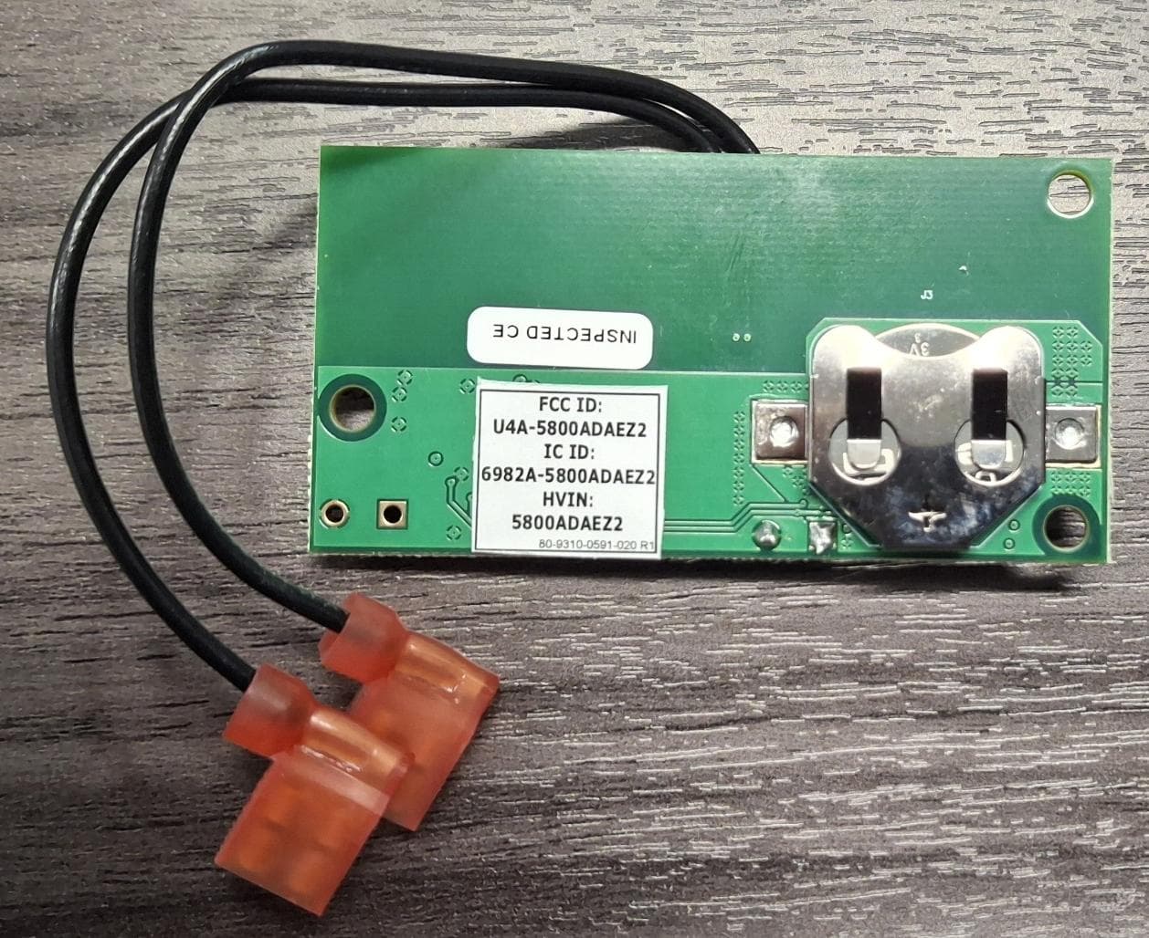
U4A5800ADAEZ2
Feb 20, 2026Wireless Interface Device
Equipment Class
DSR - Part 15 Remote Control/Security Device Transceiver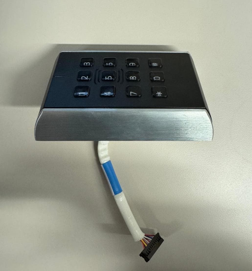
U4A-SCYMCA1K
Jul 28, 2024Aperio V3 IN100 Keypad Variant RF Module
Equipment Class
DXX - Part 15 Low Power Communication Device Transmitter
U4A-CEX100
Jun 05, 2023Access Control Lock
Equipment Class
DXX - Part 15 Low Power Communication Device Transmitter