U4A-YRHCPZW1FMZ-Wave Module for Smart Lock
ASSA ABLOY Inc.
Click to zoom
Application Details
- Equipment Class
- DXX - Part 15 Low Power Communication Device Transmitter
- Date of Grant
- Apr 09, 2020
- Application Purpose
- Original Equipment
- Date of Application
- Apr 09, 2020
- Equipment Note
- Z-Wave Module for Smart Lock
- Frequency Range
- 908.40000000 - 916.00000000
- Company
- ASSA ABLOY Inc.
- Country
- United States
Documents & Files
Document Text
Text extracted from the exhibit documents filed with the FCC. Open a document above to read the original.
Users Manual
®® Yale Z-Wave Plus v2 Smart Module Installation Guide ® Adding a Yale Z-Wave Plus v2 Smart Module to your Assure Lock & Z-Wave System 1. Open Z-Wave system's smart home or alarm app and follow instructions for removing a device 4. Press the 3 key followed by the icon 2. On your lock keypad, enter your master entry code followed by the icon 5. Remove Yale Smart Module from slot above battery compartment 3. Press the 7 key followed by the icon 6. If you're adding a new Yale Smart Module, follow instructions included with it • Reinstall batteries IMPORTANT: Batteries must be removed before removing Yale Smart Module: • Remove battery cover • Remove Yale Smart Module • Reinstall battery cover • Remove batteries P/N AYR-MOD-ZW3-MNL-0015 Rev A ® ® Removing a Yale Z-Wave Plus v2 Smart Module from your Assure Lock & Z-Wave System • Reinstall battery cover 2. Open Z-Wave system's smart home or alarm app on your smartphone or tablet • Reinstall batteries • Remove battery cover • Remove batteries 3. If you have Smart Start* enabled with your Z-Wave System follow in-app prompts to add a new device • Insert Yale Smart Module If you don't have smart start or are not sure, follow steps 4 - 6 4. On your lock keypad, enter your master entry code followed by the icon 6. Press the 1 key followed by the icon 5. Press the 7 key followed by the icon IMPORTANT: Batteries must be removed before inserting Yale Smart Module: 1. Install Yale Smart Module into slot above battery compartment Please use this procedure only when network primary controller is missing or otherwise inoperable. If prompted, scan QR code *SmartStart enabled products can be added into a Z-Wave network by scanning the Z-Wave QR Code present on the product with a controller providing SmartStart inclusion. No further action is required and the SmartStart product will be added automatically within 10 minutes of being switched on in network vicinity. ! Warning: Changes or modifications to this device, not expressly approved by ASSA ABLOY Residential Group could void the user's authority to operate the equipment. 24/7 Tech Support: 1-855-492-0505 • www.yalehome.com Yale® is a registered trademark of ASSA ABLOY Residential Group. Other products' brand names may be trademarks or registered trademarks of their respective owners and are mentioned for reference purposes only. © Copyright 2020. All rights reserved. Reproduction in whole or in part without the express written permission of ASSA ABLOY Residential Group is prohibited. This device is a security enabled Z-Wave Plus v2 product that is able to use encrypted Z-Wave Plus v2 messages to communicate to other security enabled Z-Wave Plus v2 products. This device must be used in conjunction with a Security Enabled Z-Wave Controller in order to fully utilize all implemented functions. This product can be operated in any Z-Wave network with other Z-Wave certified devices from other manufacturers. All non-battery operated nodes within the network will act as repeaters regardless of vendor to increase reliability of the network. Section 7.1.3 of RSS-GEN This Device complies with Industry Canada License-exempt RSS standard(s). Operation is subject to the following two conditions: 1) this device may not cause interference, and 2) this device must accept any interference, including interference that may cause undesired operation of the device. Cet appareil est conforme avec Industrie Canada RSS standard exemptes de licence(s). Son fonctionnement est soumis aux deux conditions suivantes: 1) ce dispositif ne peut causer des interférences, et 2) cet appareil doit accepter toute interférence, y compris les interférences qui peuvent causer un mauvais fonctionnement du dispositif. Class B Equipment This equipment has been tested and found to comply with the limits for a Class B digital device, pursuant to Part 15 of the FCC Rules. These limits are designed to provide reasonable protection against harmful interference in a residential installation. This equipment generates, uses, and can radiate radio frequency energy and, if not installed and used in accordance with the instructions, may cause harmful interference to radio communications. However, there is no guarantee that interference will not occur in a particular installation. If this equipment does cause harmful Interference to radio or television reception, which can be determined by turning the equipment off and on, the user is encouraged to try to correct the interference by one or more of the following measures: ŸReorient or relocate the receiving antenna. FCC: ŸConnect the equipment into an outlet on a circuit different from that to which the receiver is connected. Industry Canada: THIS DEVICE COMPLIES WITH PART 15 OF THE FCC RULES. OPERATION IS SUBJECT TO THE FOLLOWING TWO CONDITIONS. (1) THIS DEVICE MAY NOT CAUSE HARMFUL INTERFERENCE, AND (2) THIS DEVICE MUST ACCEPT ANY INTERFERENCE RECEIVED, INCLUDING INTERFERENCE THAT MAY CAUSE UNDESIRED OPERATION. ŸIncrease the separation between the equipment and receiver. Section 7.1.2 of RSS-GEN Under Industry Canada regulations, this radio transmitter may only operate using an antenna of a type and maximum (or lesser) gain approved for the transmitter by Industry Canada. To reduce potential radio interference to other users, the antenna type and its gain should be so chosen that the equivalent isotropically radiated power (e.i.r.p.) is not more than that necessary for successful communication. En vertu des règlements d'Industrie Canada, cet émetteur radio ne peut fonctionner avec une antenne d'un type et un maximum (ou moins) approuvés pour gagner de l'émetteur par Industrie Canada. Pour réduire le risque d'interférence aux autres utilisateurs, le type d'antenne et son gain doivent être choisies de façon que la puissance isotrope rayonnée équivalente (PIRE) ne dépasse pas ce qui est nécessaire pour une communication réussie. ŸConsult the dealer or an experienced radio/TV technician for help. This equipment c…
Text truncated - open the document above for the full version.
Cover Letter(s)
3/16/20 Agent’s Authorization Letter FCC ID U4A-YRHCPZW1FM I, an employee of Assa Abloy, do hereby authorize, until further notice, Jason Stewart, VPI Laboratories, 313 West 12800 South, Suite 311, Draper, UT 84020, to act on our behalf in dealings before the Federal Communications Commission with respect to all matters relating to equipment authorizations under 47 CFR. This authorization includes, but is not limited to, the signing of Form 731. I certify that no party (as defined in 47 CFR 1.2002) to this application, including myself, is subject to a denial of federal benefits, that include FCC benefits, pursuant to section 5301 of the Anti-Drug Abuse Act of 1988, 21 U.S.C., 853A Certified By: James W. Forte, P.E. Senior Product Compliance Engineer ASSA ABLOY 110 Sargent Drive New Haven, CT. 06511 Phone: (203) 821-5788 [email protected]
Cover Letter(s)
Americas Division 110 Sargent Drive New Haven, CT 06511 USA Phone: +1 203 821-5788 Fax: +1 203 498-5600 Email: [email protected] James W. Forte, P.E. Senior Product Compliance Engineer RE: CONFIDENTIALITY REQUEST Columbia, MD 21046 7435 Oakland Mills Road Equipment Authorization Branch Commission Federal Communications March 6, 2020 Sincerely, The material above contains technical data, which would customarily be guarded from competitors. arts List (BOM)4.P ircuit/Technical Description3.C lock Diagram2.B chematics1.S confidential: requests that the following documents regarding this submission for FCC ID U4A-YRHCPZW1FM be kept This letter is to comply with 47 CFR 0.457(d)(2) and 0.459 pertaining to confidential material. ASSA ABLOY Inc. To Whom It May Concern:
Cover Letter(s)
Americas Division 110 Sargent Drive New Haven, CT 06511 USA Phone: +1 203 821-5788 Fax: +1 203 603-5981 Email: [email protected] be ensured. other party. Installation will be under our control and therefore full compliance of the end product will always Please note that, this module is to be installed only by us in our end products and will not be marketed to any YRHCPZW1FM We, ASSA ABLOY Inc., are applying for a full modular approval for our device with FCC ID: The module is provided with a shield. capacitors may be located external to the shielded radio elements. 1) The radio elements of the modular transmitter must have their own shielding. The physical crystal and tuning The following numbered items correspond to requirements listed in 15.212 of the FCC rules. provided for power and data communication. Antennas are external to our module. This transceiver is a complete RF module with an integral reference oscillator. External connections are FCC 15.212(b). The following information is being provided regarding full modular approval per the requirements of CFR 47 provision of Sec. 15.203 is not applicable to modules but can apply to limited modular approvals under paragraph (at all connections between the module and the antenna, including the cable). The ``professional installation'' 15.204(b) and 15.204(c). The antenna must either be permanently attached or employ a ``unique'' antenna coupler The modular transmitter must comply with the antenna and transmission system requirements of Sec. Sec. 15.203, 4) The power supply is regulated as per the schematic diagram. The modular transmitter must have its own power supply regulation.3) The module is designed using a System on Chip (SoC) solution. There are no exposed modulation inputs. the module will comply with part 15 requirements under conditions of excessive data rates or over-modulation. The modular transmitter must have buffered modulation/data inputs (if such inputs are provided) to ensure that 2) complies with this requirement. The antenna are permanently attached to the module. They are not detachable and therefore our module (b) of this section. To Whom It May Concern, Re: Single Limited Modular Approval Request CC: Curtis-Straus LLC TCB Columbia, MD 21046-1609 7435 Oakland Mills Road Federal Communications Commission April 8, 2020 James W. Forte, P.E. Senior Product Compliance Engineer labeling warnings can be found in the installation manual of the module. Our module has a label as described in the label exhibit that complies with this requirement. End-product equipment authorization. requirement. In the latter case, a copy of these instructions must be included in the application for authorization,or, must provide adequate instructions along with the module which explain this may either provide such a label, an example of which must be included in the application for equipment FCC ID:XYZMODEL1.” Any similar wording that expresses the same meaning may be used. The Grantee use wording such as the following: “Contains Transmitter Module FCC ID: XYZMODEL1” or “Contains the module is installed must also display a label referring to the enclosed module. This exterior label can is not visible when the module is installed inside another device, then the outside of the device into which transmitter must be labeled with its own FCC identification number, and, if the FCC identification number of electronically displaying its FCC identification number. If using a permanently affixed label, the modular 6) The modular transmitter must be equipped with either a permanently affixed label or must be capable Our module was tested in stand-alone configuration and therefore complies with this requirement. during testing shall beunmodified and commercially available (see Sec. 15.31(i)). module and supportingequipment. Any accessories, peripherals, or support equipment connected to the module or, if that length isunknown, at least 10 centimeters to insure that there is no coupling between the case of the marketed with themodule (see Sec. 15.27(a)). The length of these lines shall be the length typical of actual use lines anddata input/output lines connected to the module must not contain ferrites, unless they will be batterypowered, it must comply with the AC line conducted requirements found in Sec. 15.207. AC or DC power anotherdevice during testing for compliance with part 15 requirements. Unless the transmitter module will be 5) The modular transmitter must be tested in a stand-alone configuration, i.e., the module must not be inside Sincerely, the end product will always be ensured. will not be marketed to any other party. Installation will be under our control and therefore full compliance of Our module complies with this requirement. This module is to be installed only by us in our end products and configuration. 8) The modular transmitter must comply with any applicable RF exposure requirements in its final Our module complies with this requirement. for equipment authorization. module to explain any such requirements. A copy of these instructions must be included in the application apply to a complete transmitter and the manufacturer must provide adequate instructions along with the 7) The modular transmitter must comply with any specific rules or operating requirements that ordinarily
External Photos
313 West 12800 South, Suite 311, Draper, UT 84020 • (801) 260-4040 YRHCP_ExtPho.docx Page 1 of 6 PROPRIETARY External Photographs Photograph 1 – Front View of the EUT 313 West 12800 South, Suite 311, Draper, UT 84020 • (801) 260-4040 YRHCP_ExtPho.docx Page 2 of 6 PROPRIETARY Photograph 2 – Back View of the EUT 313 West 12800 South, Suite 311, Draper, UT 84020 • (801) 260-4040 YRHCP_ExtPho.docx Page 3 of 6 PROPRIETARY Photograph 3 – View of the Right Side of the EUT 313 West 12800 South, Suite 311, Draper, UT 84020 • (801) 260-4040 YRHCP_ExtPho.docx Page 4 of 6 PROPRIETARY Photograph 4 – View of the Left Side of the EUT 313 West 12800 South, Suite 311, Draper, UT 84020 • (801) 260-4040 YRHCP_ExtPho.docx Page 5 of 6 PROPRIETARY Photograph 5 – View of the Top Side of the EUT 313 West 12800 South, Suite 311, Draper, UT 84020 • (801) 260-4040 YRHCP_ExtPho.docx Page 6 of 6 PROPRIETARY Photograph 6 – View of the Bottom Side of the EUT
Internal Photos
313 West 12800 South, Suite 311, Draper, UT 84020 • (801) 260-4040 YRHCP_IntPho.docx Page 1 of 2 PROPRIETARY Internal Photographs Photograph 1 – Top View of the PCB with Shield Photograph 2 – View of the Bottom Side of the PCB PCB Antenna 313 West 12800 South, Suite 311, Draper, UT 84020 • (801) 260-4040 YRHCP_IntPho.docx Page 2 of 2 PROPRIETARY Photograph 3 – View of the Circuitry under the RF Shield Photograph 4 – View of the PCB inside of Housing
Test Report
313 West 12800 South, Suite 311 Draper, UT 84020 (801) 260-4040 Test Report Certification FCC ID U4A-YRHCPZW1FM Equipment Under Test AYR-MOD-ZW3-USA Test Report Serial No V050705_01 Date of Test January 14, 2020 Report Issue Date January 22, 2020 Test Specifications: Applicant: FCC Part 15, Subpart C Assa Abloy, Inc. 110 Sargent Drive New Haven, CT 06511 U.S.A. 313 West 12800 South, Suite 311, Draper, UT 84020 • (801) 260-4040 V050705_01_AYR-MOD-ZW3-USA_FCC_Sub_C.docx Page 2 of 35 PROPRIETARY Certification of Engineering Report This report has been prepared by VPI Laboratories, Inc. to document compliance of the device described below with the requirements of Federal Communications Commission (FCC) Part 15, Subpart C. This report may be reproduced in full. Partial reproduction of this report may only be made with the written consent of the laboratory. The results in this report apply only to the sample tested. Applicant Assa Abloy, Inc. Manufacturer Assa Abloy, Inc. Brand Name Yale Model Number AYR-MOD-ZW3-USA FCC ID U4A-YRHCPZW1FM On this 22 nd day of January 2020, I, individually and for VPI Laboratories, Inc., certify that the statements made in this engineering report are true, complete, and correct to the best of my knowledge, and are made in good faith. Although NVLAP has accredited the VPI Laboratories, Inc. EMC testing facilities, this report must not be used to claim product certification, approval, or endorsement by NVLAP, NIST, or any agency of the federal government. VPI Laboratories, Inc. Tested by: Norman P. Hansen Reviewed by: Benjamin N. Antczak 313 West 12800 South, Suite 311, Draper, UT 84020 • (801) 260-4040 V050705_01_AYR-MOD-ZW3-USA_FCC_Sub_C.docx Page 3 of 35 PROPRIETARY Revision History Revision Description Date 01 Original Report Release January 22, 2020 313 West 12800 South, Suite 311, Draper, UT 84020 • (801) 260-4040 V050705_01_AYR-MOD-ZW3-USA_FCC_Sub_C.docx Page 4 of 35 PROPRIETARY Table of Contents 1 Client Information ................................................................................................................................. 5 1.1 Applicant ....................................................................................................................................... 5 1.2 Manufacturer ................................................................................................................................. 5 2 Equipment Under Test (EUT) ............................................................................................................... 6 2.1 Identification of EUT .................................................................................................................... 6 2.2 Description of EUT ....................................................................................................................... 6 2.3 EUT and Support Equipment ........................................................................................................ 6 2.4 Interface Ports on EUT ................................................................................................................. 7 2.5 Modification Incorporated/Special Accessories on EUT .............................................................. 7 2.6 Deviation from Test Standard ....................................................................................................... 7 3 Test Specification, Methods and Procedures ........................................................................................ 8 3.1 Test Specification .......................................................................................................................... 8 3.2 Methods & Procedures .................................................................................................................. 8 3.3 Test Procedure .............................................................................................................................. 9 4 Operation of EUT During Testing ...................................................................................................... 10 4.1 Operating Environment ............................................................................................................... 10 4.2 Operating Modes ......................................................................................................................... 10 4.3 EUT Exercise Software ............................................................................................................... 10 5 Summary of Test Results .................................................................................................................... 11 5.1 FCC Part 15, Subpart C .............................................................................................................. 11 5.2 Result .......................................................................................................................................... 11 6 Measurements, Examinations and Derived Results ............................................................................ 12 6.1 General Comments ...................................................................................................................... 12 6.2 Test Results ................................................................................................................................. 12 6.3 Sample Field Strength Calculation ............................................................................................. 20 7 Test Procedures and Test Equipment .................................................................................................. 21 7.1 Conducted Emissions at Mains Ports .......................................................................................... 21 7.2 Radiated Emissions ..................................................................................................................... 22 7.3 Equipment Calibration ...............................…
Text truncated - open the document above for the full version.
Test Setup Photos
313 West 12800 South, Suite 311, Draper, UT 84020 • (801) 260-4040 YRHCP_Tsup.docx Page 1 of 7 PROPRIETARY Test Set Up Photographs Radiated Photograph 1: Front View Radiated Emissions, Worst Case – Below 1000 MHz Configuration Photograph 2: Back View Radiated Emissions Worst Case 30 MHz to 1000 Configuration 313 West 12800 South, Suite 311, Draper, UT 84020 • (801) 260-4040 YRHCP_Tsup.docx Page 2 of 7 PROPRIETARY Photograph 3: Front View Radiated Emissions Worst Case – Above 1000 MHz Configuration Photograph 4: Back View Radiated Emissions Worst Case – Above 1000 MHz Configuration 313 West 12800 South, Suite 311, Draper, UT 84020 • (801) 260-4040 YRHCP_Tsup.docx Page 3 of 7 PROPRIETARY Photograph 5: Front View Conducted Emissions Worst-Case Configuration Photograph 6: Back View Conducted Emissions Worst-Case Configuration 313 West 12800 South, Suite 311, Draper, UT 84020 • (801) 260-4040 YRHCP_Tsup.docx Page 4 of 7 PROPRIETARY Photograph 7: Flat Placement Worst Case Photograph 8: Edge Placement 313 West 12800 South, Suite 311, Draper, UT 84020 • (801) 260-4040 YRHCP_Tsup.docx Page 5 of 7 PROPRIETARY Photograph 9: Vertical Placement 313 West 12800 South, Suite 311, Draper, UT 84020 • (801) 260-4040 YRHCP_Tsup.docx Page 6 of 7 PROPRIETARY Reference Test Set Up Photographs Photograph 10: Reference Photo of Test Setup for Emissions Below 30 MHz Photograph 11: Reference Photo of Test Setup for Emissions From 30 MHz to 1000 MHz 313 West 12800 South, Suite 311, Draper, UT 84020 • (801) 260-4040 YRHCP_Tsup.docx Page 7 of 7 PROPRIETARY Photograph 12: Reference Photo of Test Setup for Emissions Above 1000 MHz
Contact Information
Applicant
James Forte(Senior Product Compliance Engineer)
Test Firm
VPI TechnologyJason Stewart
[email protected]801-495-2310
Technical Specifications
| # | Rule Parts | Frequency Range | Power Output |
|---|---|---|---|
| 1 | 15C | 908.4 MHz - 916 MHz | - |
Other Applications from ASSA ABLOY Inc.
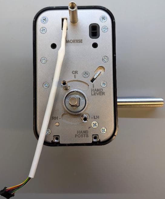
U4A-LNK100
Sep 03, 2026Real-Time Wireless Locks
Equipment Class
DTS - Digital Transmission System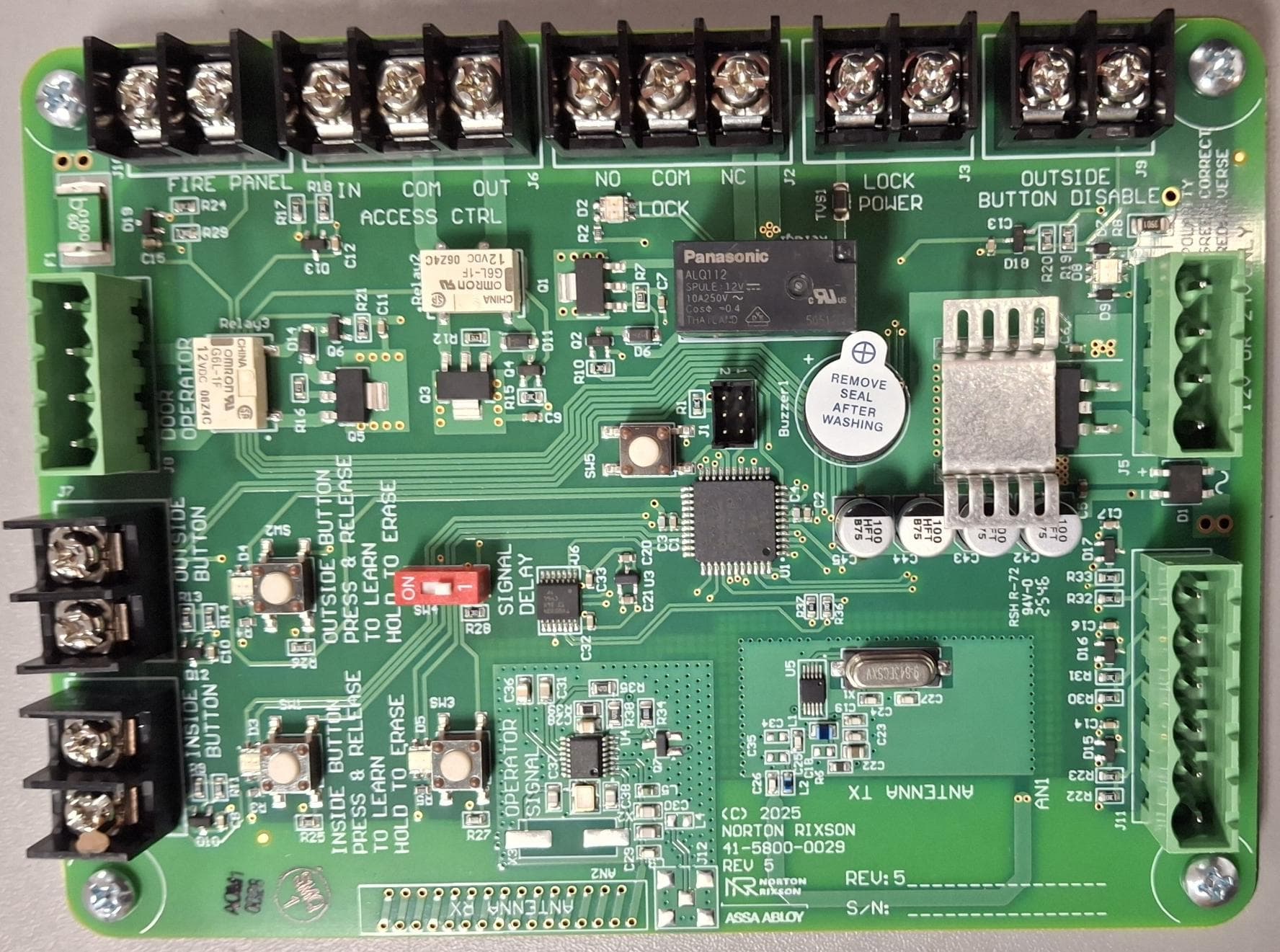
U4A-ADA1028W2
Aug 07, 2026Wireless Interface Device
Equipment Class
DSR - Part 15 Remote Control/Security Device Transceiver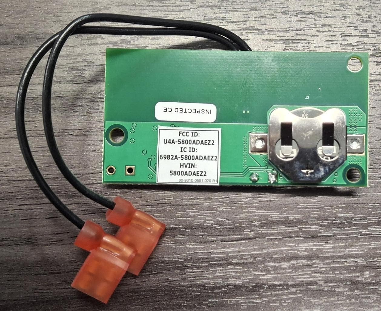
U4A5800ADAEZ2
Feb 20, 2026Wireless Interface Device
Equipment Class
DSR - Part 15 Remote Control/Security Device Transceiver
U4A-SCYMCA1K
Jul 28, 2024Aperio V3 IN100 Keypad Variant RF Module
Equipment Class
DXX - Part 15 Low Power Communication Device Transmitter
U4A-CEX100
Jun 05, 2023Access Control Lock
Equipment Class
DXX - Part 15 Low Power Communication Device Transmitter