U62-0766Relays data from a star network to a mesh network
SynapSense Corporation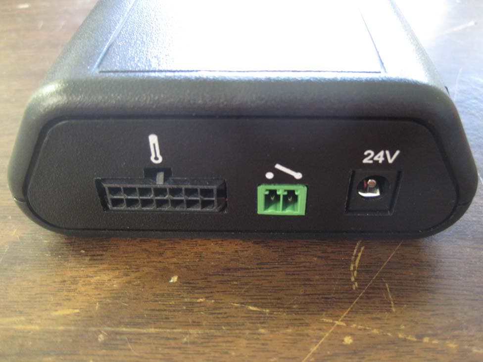
Click to zoom
Application Details
- Equipment Class
- DTS - Digital Transmission System
- Date of Grant
- May 02, 2011
- Application Purpose
- Original Equipment
- Date of Application
- Apr 23, 2011
- Equipment Note
- Relays data from a star network to a mesh network
- Frequency Range
- 2402.00000000 - 2481.00000000
- Company
- SynapSense Corporation
- Country
- United States
Documents & Files
Document Text
Text extracted from the exhibit documents filed with the FCC. Open a document above to read the original.
Users Manual
2365 Iron Point Rd Suite 100 Folsom CA 95630 Wireless Sensor Network Node Installation and User Manual Document Number 85-0xxx-001 Author Pat Weston Revision Prerelease 4 Date 19 October 2010 This manual covers the general installation of the following SynapSense Wireless Sensor Network Nodes: • 99-0039-002 • 99-0039-011 • 99-0039-012 • 99-0039-015 • 99-0189-001 • 99-0217-001 • 99-0331-001 • 99-0348-001 • 99-0360-001 • 99-0766-001 Regulatory Information Notice to Users: This equipment has been tested and found to comply with the limits for a Class A digital device, pursuant to Part 15 of the FCC Rules. These limits are designed to provide reasonable protection against harmful interference when the equipment is operated in a commercial environment. This equipment generates, uses, and can radiate radio frequency energy and, if not installed and used in accordance with the instruction manual, may cause harmful interference to radio communications. Operation of this equipment in a residential area is likely to cause harmful interference in which case the user will be required to correct the interference at his own expense. FCC Statement: This device complies with part 15 of the FCC Rules. Operation is subject to the following two conditions: (1) This device may not cause harmful interference, and (2) this device must accept any interference received, including interference that may cause undesired operation. Changes or modifications not expressly approved by the party responsible for compliance could void the user's authority to operate the equipment. The antenna(s) used for this transmitter must not be co-located or operating in conjunction with any other antenna or transmitter. Antenna Statement: Only the antenna supplied with this unit may be used. Any attempt to modify this antenna or substitute a different antenna by any means shall void the warranty and will void the FCC approval to operate this equipment. In the event an antenna is broken, a replacement antenna may be obtained by contacting the Product Support Center listed in the warranty section of this manual. CE Statement: This equipment has been tested and found to comply with the limits of the European Council Directive on the approximation of the law of the member states relating to electromagnetic compatibility (89/336/EEC) according to EN 55022 Class B. Industry Canada Equipment Notice: The Industry Canada certification identifies certified equipment. This certification means that the equipment meets certain telecommunications network protective, operational and safety requirements as prescribed in the appropriate Terminal Equipment Technical Document(s). The Department does not guarantee the equipment will operate to the user's satisfaction. Before installing this equipment, users should ensure that it is permissible to be connected to the facilities of the local telecommunications company. The equipment must also be installed using an acceptable method of connection. The customer should be aware that compliance with the above conditions may not prevent degradation of service in some situations. Repairs to certified equipment should be coordinated by a representative designated by the supplier. Any repairs or alterations made by the user to this equipment, or equipment malfunctions, may give the telecommunications company cause to request the user to disconnect the equipment. Users should ensure, for their own protection, that the electrical ground connectors of the power utility, telephone lines and internal metallic water pipe system, if present, are connected together. This presentation may be particularly important in rural areas. Caution: Users should not attempt to make such connections themselves, but should contact the appropriate electric inspection authority or electrician, as appropriate. This device has been designed to operate with the antennas listed below, and having a maximum gain of 2.2 dBi. Antennas not included in this list or having a gain greater than 2.2 dBi are strictly prohibited for use with this device. The required antenna impedance is 50 ohms. SynapSense Antenna P/N78-0036-001 Warranty Information Limited One Year Warranty Our company warrants that for two years from the date of purchase, it will replace this product if found to be defective in materials or workmanship. For a prompt, no charge replacement of equivalent product, return the defective product postage prepaid to the appropriate address. Product Support Center 2365 Iron Point Road, Suite 100 Folsom, CA 95630 United States of America This replacement is the company's sole obligation under this warranty. SynapSense, Inc. will not be responsible for any incidental or consequential damages or for any loss arising in connection with the use or inability to use this product. Some states/provinces do not allow the exclusion or limitation of incidental or consequential damages, so the above limitation or exclusion may not apply to you. This warranty excludes defects or damage due to misuse, abuse, or neglect. This warranty gives you specific legal rights, and you may also have other rights, which vary from state to state/province to province. 1. Operation The SynapNet Node is designed to work in conjunction with a SynapNet Gateway device and the SynapSoft console. Please be sure you have correctly configured SynapSoft on the gateway computer prior to continuing. SynapNet nodes can be added to an existing SynapSense Wireless Network (driven by a SynapNet Gateway) or be used to form a network. Note that battery life will be compromised if the SynapNet Node is not in range of an active gateway device or other SynapNet Node which is part of a running network. Devices that are powered by external power adapters must have the power adapter placed outside the server cabinet as the maximum operating temperature of the adapter is +40°C, whereas the device mounted inside the cabinet can operate to +60°C. Installing/Replacing the external antenna…
Text truncated - open the document above for the full version.
Cover Letter(s)
2365 Iron Point Rd, Suite 100 Folsom, CA USA 95630 T:+1-916-294-0110 F: +1-916-294-0270 December 3, 2010 To Whom It May Concern: We the undersigned hereby delegate power of attorney to CKC Certification Services, LLC (CKC CS) to act on our behalf in matters of radio equipment certification. CKC CS is appointed as an agent to sign applications before regulatory agency(ies) on our behalf, and to receive and exchange data between our company and the agency(ies). Sincerely, Pat Weston VP Engineering SynapSense Corporation 2365 Iron Point Road, Suite 100 Folsom, CA 95630 916-293-0934
Cover Letter(s)
2365 Iron Point Rd Suite 100 Folsom CA 95630 SynapSense Corporation 2365 Iron Point Rd., Suite 100 Folsom, CA 95630 916-293-0934 FCC Confidential Authorization December 3, 2010 FEDERAL COMMUNICATIONS COMMISSIONS Authorization and Evaluation Division 7435 Oakland Mills Road Columbia, MD 21046 Subject: Confidentiality Request regarding application for certification of FCC ID: U62-0766 In accordance with Sections 0.457 and 0.459 of the Commission’s Rules, SynapSense Corporation hereby requests long-term confidential treatment of information accompanying this application as outlined below: • Block Diagram • Schematics • Operation Description The above materials contain proprietary and confidential information not customarily released to the public. The public disclosure of these materials provides unjustified benefits to its competitors in the market. Sincerely, Pat Weston VP Engineering SynapSense Corporation
ID Label/Location Info
Regulatory Label, Sand Crawler SIZE FSCM NO DWG NO REV A 60-0766-001 C SCALE 2:1 SHEET 1 of 1 2.0 1.5 Dimensions in inches Model: 0766FCC ID: U62-0766, IC: 7265A-0766Contains Transceiver Module: FCC ID: U62-SRA100, IC: 7265A-SRA100 4 Part Number: 99-0766-001 This device complies with part 15 of the FCC Rules. Operation is subject to the following two condition s: (1) This device may not cause harmful interference, and (2) This device must accept any interference received, including interference that may cause undesired operation. 1. Material: See BOM for Blank Label2. Text: Arial or equivalent, size per best fit3. After printing, verify text does not smear/rub4. Apply SynapSense and other Logo’s per files pro vided 5. Serial Number and Human Readable Barcode: See Notes Below Serial Number (Human Readable): PR = Fixed character (Pride); (AM for Amperor)YY = Year (2010 = 10)WW = Work Week (assigned per manufacturer calendar)ZZZZ = Sequentially assigned number (hex-decimal 0- F) XX = SC (Product Code) Barcode:Code 128, 0.1" Tall min., verify barcode is scannab le Barcode matches human readable characters PRYYWWZZZZXX 5
Parts List/Tune Up Info
Synapsense Item NumberDescriptionEng QtyProd QtyRef DesDigikey PNManufacturerMnfr PN 31-0023-003Cap, 0.01uF 50V X7R 0402 (RoHS Comp)22C1, C59PCC2270CT-NDPanasonicECJ-0EB1E103K 31-0025-003Cap, 10pF 50v NP0 040233C11, C18, C20PCC100CQCT-NDPanasonicECJ-0EC1H100D 31-0075-003Cap, 0.1uF X7R 16V 0402 (RoHS Comp)4141C2-C10, C12, C14-C17, C19, C22, C23, C30, C31, C36, C40, C47, C49-C54, C62, C66, C73, C75, C77, C87-C92, C101, C113587-1451-1-NDTaiyo YudenEMK105B7104KV-F 31-0488-001CAP CER .1UF 50V 10% X7R 060333C55, C102, C103490-1519-1-NDMurataGRM188R71H104KA93D 31-0073-003CAP CER 22PF 50V 5% C0G 040222C63, C64490-1283-1-NDMurataGRM1555C1H220JZ01D 31-0070-003CAP 33000PF 10V CERAMIC X5R 04022323 C13, C21, C24-C27, C29, C32, C41, C42, C45, C67, C71, C74, C82, C84, C85, C94-C99PCC2140CT-NDPanasonicECJ-0EB1A333K 31-0613-001CAP CER 1.0PF 50V 0402 HIGH FREQ22C38, C39587-1007-1-NDTaiyo YudenUVK105CH010BW-F 31-0612-001CAP CER 1.5PF 50V 0402 HIGH FREQ11C37587-1011-1-NDTaiyo YudenUVK105CH1R5BW-F 31-0630-001CAP 2200PF 50V CERAMIC X7R 040266C43, C70 C78-C81399-3068-1-NDKemetC0402C222K5RACTU 31-0631-001CAP CER 1.0UF 16V 10% X5R 060322C28, C61490-1536-1-NDMurataGRM188R61C105KA93D 31-0645-001CAP TANTALUM 10UF 16V 10% SMD11C35495-2236-2-NDKemetB45196H3106K109 31-0689-001CAP 47UF 35V ELECT HD SMD11C46PCE4968CT-NDPanasonicEEE-HDV470XAP 31-0015-001Cap, 4.7uF X5R 25V 0805 (RoHS Comp)66C48, C56, C57, C60, C65, C86PCC2321CT-NDPanasonicECJ-2FB1E475M 31-0687-001CAP 10UF 50V CERAMIC F 121011C58PCC2308CT-NDPanasonicECJ-4YF1H106Z 31-0767-001CAP CER 2.2UF 10V 20% X5R 060333C68, C72, C76490-1546-1-NDMurataGRM188R61A225ME34D 31-0768-001CAP CER 470PF 50V 5% C0G 040211C69490-1297-1-NDMurataGRM1555C1H471JA01D 41-0769-001DIODE SCHOTTKY 40V 1A SOD12355D1-D3, D5, D6MBRX140TPMSCT-NDMicro CommercialMBRX140-TP 41-0691-001DIODE SCHOTTKY 60V 3A SMA11D4B360A-FDICT-NDDiodes Inc.B360A-13-F 40-0692-001FUSE RESETTABLE .75A 30V SMD11F1MF-SM075CT-NDBournsMF-SM075-2 36-0130-002-B CONN RECEPT 2MM 8POS VERT SMT JTAG (RoHS Comp)10J1WM18699-NDMolex79109-1003 36-0190-001Header, SMT, Molex Microfit, 7x2 Right Angle (RoHS Comp)11J3538-43045-1411Molex43045-1411 36-0169-002Connector, Power Jack 2.1 x 5.5mm, TH (RoHS Comp)11J4CP-002A-NDCUI Inc.PJ-002A 36-0633-001CONN HEADER FMAL 10PS.1" DL GOLD11J5S7108-NDSullinsPPPC052LFBN-RC 36-0770-001CONN RCPT MICRO USB TYPE AB11J6A97799CT-NDTyco1981584-1 36-0771-001CONN FPC/FFC 60POS .5MM R/A SMD00J7609-3439-1-NDFCI10085901-6015ELF 43-0078-001FERRITE 1.5A 40 OHM 0805 SMD (RoHS Comp55L1-L4, L9240-2389-1-NDStewardMI0805K400R-10 43-0634-001INDUCTOR 3.9NH 170MA 040222L5, L7490-1131-1-NDMurataLQP15MN3N9B02D 43-0635-001INDUCTOR 4.7NH 160MA 040211L6490-1132-1-NDMurataLQP15MN4N7B02D 43-0772-001COIL CHOKE 22UH SHIELDED SMD11L8PCD2267CT-NDPanasonicELL-6PG220M 41-0077-003LED 470NM BLUE CLEAR 0603 SMD11LED1511-1589-1-NDRohmSML-E12BC7TT86 41-0077-001-A LED, Red, Clear Lens, 0603 SMT (RoHS Comp)44LED2, LED4, LED5, LED9511-1298-1-NDRohmSML-310LTT86 41-0077-002LED 1.6X0.8MM 568NM GRN CLR SMD33LED3, LED6, LED8754-1118-1-NDKingbrightAPT1608MGC 41-0491-001LED, ORANGE, 0603, SMD (RoHS Comp)11LED7511-1297-1-NDRohmSML-310DTT86 26-0601-001LIGHT PIPE, 3x5.5MM, RA, RECT, SMD (RoHS COMP)33LP1-LP367-1858-NDLumexLPF-R011362S 41-0026-001MOSFET PWR P-CHAN 1.3A 20V SOT2322Q1, Q2NTR1P02LT1GOSCT-NDOn SemiconductorNTR1P02LT1G 41-0661-001MOSFET N-CH 60V 115MA SOT-2333Q3-Q52N7002NCT-NDFairchild2N7002 29-0093-003Resistor, 43k Ohm, 1%, 0402 (RoHS Comp)11R1311-43.0KLRCT-NDYageoRC0402FR-0743KL 29-0146-003Resistor, 10k ohm 0.1% 0402 (RoHS Comp)1515R10, R12, R13, R16, R17, R18, R20, R24, R25, R27, R28, R30, R31, R33, R44 P10KDCCT-NDPanasonicERA-2AEB103X 29-0507-001RES 20K OHM 1/16W 0.1% 0402 SMD (RoHs Comp)99R11, R14, R18, R21-R23, R26, R29, R32 RG10P20KBCT-NDSusumuRG1005P-203-B-T5 29-0092-003-AResistor, 10k Ohm, 0402 (RoHS Comp)66R8, R15, R36, R45, R48, R51311-10.0KLRCT-NDYageoRC0402FR-0710KL 29-0087-003Resistor, 100 ohm 0402 (RoHS Comp)55R2, R5, R37, R38, R46311-100JRTR-NDYageoRC0402JR-07100RL 29-0377-001RES 0 OHM 1/10W 5% 0603 SMD (RoHS Comp)11R4P0.0GTR-NDPanasonicERJ-3GEY0R00V 29-0088-003-A Resistor, 220 ohm, 0402 (RoHS Comp)44R3, R6, R34, R47RHM220LCT-NDRohmMCR01MZPF2200 29-0773-001RES 4.70K OHM 1/10W 1% 0402 SMD22R39, R40P4.70KLCT-NDPanasonicERJ-2RKF4701X 29-0049-003Resistor, 11.3k ohm 0.5% 040211R42RR05P11.3KDCT-NDSusumuRR0510P-1132-D 29-0141-003Resistor, 110k ohm 1% 040211R41P110KLCT-NDPanasonicERJ-2RKF1103X 29-0774-001RES .20 OHM 1/4W 1% 0805 SMD11R43RHM.20MCT-NDRohmMCR10EZHFLR200 29-0706-001RES, 39.0 Ohm, 1%, 0402 (RoHS COMP)22R49, R50P39.0LCT-NDPanasonicERJ-2RKF39R0X 29-0574-001RES 120 OHM 1/10W 1% 0603 SMD22R9, R52311-120HRCT-NDYageoRC0603FR-07120RL 29-0097-003Resistor, 5.1M Ohm, 0402 (RoHS Comp)11R7P5.1MJCT-NDPanasonicERJ-2GEJ515X 29-0440-001RES 22.0K OHM 1/16W 1% 0402 SMD11R35311-22.0KLRCT-NDYageoRC0402FR-0722KL 40-0775-001SWITCH TACT SPST W/O GND SMD22SW1, SW2SW1020CT-NDOmronB3U-1000P 40-0522-001SWITCH TACT SILVR 200GF GULLWING22SW3, SW4401-1097-1-NDC&KKSS221GLFS 32-0101-001IC, DS2411 Silicon Serial Number SOT-23 (RoHS Comp)11IC1DS2411R+CT-NDMaximDS2411R+ 11-0606-001PCBA, SUPER NODE, RADIO BOARD11U1Synapsense11-0606-001 32-0525-001IC SRL FLASH 32MBIT 2.7V 8-SOIC11U3AT25DF321-SU-NDAtmelAT25DF321-SU 32-0524-001IC MCU 16BIT 256K FLASH 100-LQFP11U4296-23859-6-NDTexas InstrumentsMSP430F5438IPZR 32-0506-001IC OPAMP GP 5.5MHZ QUAD 14TSSOP22U5, U7296-22565-1-NDTexas InstrumentsOPA4376AIPWR 32-0714-001IC, TEMP/HUM SENSOR, HIGH PRECISION, 4-PINS (RoHS COMP) 10U6SensirionSHT75 32-0639-001Low Power 2.4GHz Wireless Transceiver with 8051 MCU11U8NRF24LE1-Q48-TNordic SemiNRF24LE1-F16Q48-T 32-0776-001IC SDRAM 64MBIT 133MHZ 54TSOP00U9557-1088-1-NDMicron TechMT48LC4M16A2P-75:G TR 32-0777-001IC LDO REG 300MA 3.3V SOT223-311U11MCP1824ST-3302E/DBCT-NDMicrochipMCP1824ST-3302E/DB 32-0778-001IC MCU AVR32 256KB FLASH 144LQFP11U12AT32UC3A0256-ALUT-NDAtmelAT32UC3A0256-ALUT 41-0580-001DIODE ARRAY ESD 5.0V LLP75-6A11U13751-1413-1-NDVishayGMF05C-HS3-GS08 32-0779-001IC REG …
Text truncated - open the document above for the full version.
RF Exposure Info
Page 1 of 5 91081-24A MAXIMUM PERMISSIBLE EXPOSURE ADDENDUM REPORT FOR THE 0766, P3 Controller DATE OF ISSUE: January 21, 2011 PREPARED FOR: SynapSense Corporation 2365 Iron Point Road, Suite 100 Folsom CA 95630 PREPARED BY: Eddie Wong CKC Laboratories, Inc. 5046 Sierra Pines Drive Mariposa, CA 95338 W.O. No.: 91081 Report No.: 91081-24A Page 2 of 5 91081-24A Revision History- Purpose of Test Original: To demonstrate compliance with United States RF Exposure requirements for Mobile Equipment (devices used >20cm from the body), where Maximum Permissible Exposure (MPE) Calculations apply. Addendum A: To replace Maximum Permissible Exposure (MPE) Calculations of the 0766, P3 Controller, due to an error in the base report, 91081-9. United States MPE Limits in accordance with 1.1310: Occupational / Controlled Exposure Frequency Range (MHz) Electric Field Strength (V/m) Magnetic Field Strength (A/m) Power Density (mW/cm 2 ) Averaging Time (minutes) 0.3-3.0 614 1.63 *(100) 6 3.0-30 1842/f 4.89/f *(900/f2) 6 30-300 61.4 0.163 1 6 300-1500 --- --- f/300 6 1500-100,000 --- --- 5 6 General Population / Uncontrolled Exposure Frequency Range (MHz) Electric Field Strength (V/m) Magnetic Field Strength (A/m) Power Density (mW/cm 2 ) Averaging Time (minutes) 0.3-1.34 614 1.63 *(100) 30 1.34-30 824/f 2.19/f *(180/f2) 30 30-300 27.5 0.073 0.2 30 300-1500 --- --- f/1500 30 1500-100,000 --- --- 1 30 Note: Limit is calculated based on the mid-band frequency used in the operating frequency range. Page 3 of 5 91081-24A Canadian MPE Limits in accordance with RSS-102: Occupational / Controlled Exposure: General Population / Uncontrolled Exposure Page 4 of 5 91081-24A Equipment operational details: Operating Frequency (MHz) Measured Output Power (dBm) Maximum Mobile Antenna Gain (dBi) Maximum EIRP (dBm) 2440 -18.4 6 -12.4 Measurements based from EMC Test Report:, # 91081-9A Device and Antenna Operating Configuration: Device operating at maximum output power with continuous transmission of modulated data. Test Procedure: This equipment is evaluated in accordance with the guidelines set forth in OET Guide 65 & ANSI C95.1 for the US and Health Canada Safety Code 6 & RSS 102 for Canada. Other Considerations: None . . MPE Calculations: Limit used: Occupational / Controlled Exposure X General Population / Uncontrolled Exposure MPE Limit = 1 (mW/cm 2 ) 2 2 4 )/( d EIRP cmmWDensityPower π = Given: EIRP in mW and d in cm EIRP (mW) Distance (cm) Power Density (mW/cm 2 ) Limit (mW/cm 2 ) Power Density (W/m 2 ) Limit (W/m 2 ) 0.058 20 0.0000023 1 0.000023 10 Page 5 of 5 91081-24A Statement of Compliance: This device demonstrates compliance under the operating conditions specified in this document. Under normal operating conditions, the antenna is designed to be installed in accordance with the manufacturer’s instructions in such a manor to maintain the minimum separation distance. The MPE calculations shown above demonstrate compliance to the provisions of US and Canadian requirements. As can be seen from the MPE results, this device passes the specified limits at a distance of 20cm at the maximum output power under normal operating conditions.
RF Exposure Info
The output power of this product is below the threshold requiring RF exposure evaluation. This device is exempt from RF Exposure review.
Test Report
This report c written cons e TE S CERT #803 803.05 ontains a total of ent of CKC Laborat STING 3.01, 803.02, 5, 803.06 36 pages and ma tories, Inc. Syna ADD Te FCC Par This test rep testing perfo of ISO/IEC 1 CKC Laborato We strive t o sound, adapt our custome processes, bu ay be reproduced apSens DENDUM TO 0766, ested To The rt 15 Subpar RSS Report Date of is port bears th ormed herein 17025 under ories, Inc. o create long‐t tive, customer ers’ unique EM ut rather as th in full only. Partia se Corp TEST REPOR P3 Contro e Following S rt C Sections and ‐210 Issue 8 t No.: 91081‐ ssue: March 9, e accreditati o meets the tes the applicab term, trust ba r first testing MC challenges, e reason we a al reproduction m poratio RT 91081‐9A ller Standards: s 15.207, 15. 8 ‐9B 2011 on symbol ind st and reporti ble scope of sed relations h services. We , not as an int are in business may only be done on A .247 dicating that ing requireme EMC testing hips by provid embrace each terruption to . with the the ents for ding h of set Page 2of 36 Report No.: 91081‐9B TABLE OF CONTENTS Administrative Information ........................................................................................................................................... 3 Test Report Information ............................................................................................................................................ 3 Revision History ......................................................................................................................................................... 3 Report Authorization ................................................................................................................................................. 3 Test Facility Information ............................................................................................................................................ 4 Site Registration & Accreditation Information .......................................................................................................... 4 Summary of Results ................................................................................................................................................... 5 Conditions During Testing ......................................................................................................................................... 5 Equipment Under Test ............................................................................................................................................... 6 Peripheral Devices ..................................................................................................................................................... 6 FCC Part 15 Subpart C .................................................................................................................................................... 7 15.207 AC Conducted Emissions................................................................................................................................ 7 15.225(a) Occupied Bandwidth ............................................................................................................................... 14 15.247(b) Peak Output Power ................................................................................................................................. 17 15.247(d) Bandedge ................................................................................................................................................ 20 15.247(d) Spurious Radiated Emissions ................................................................................................................... 23 15.247(e) Power Spectral Density ........................................................................................................................... 28 RSS 210 ........................................................................................................................................................................ 32 99% Bandwidth ............................................................................................................................... ......................... 32 Supplemental Information .......................................................................................................................................... 35 Measurement Uncertainty ...................................................................................................................................... 35 Emissions Test Details .............................................................................................................................................. 35 Page 3of 36 Report No.: 91081‐9B ADMINISTRATIVE INFORMATION Test Report Information REPORT PREPARED FOR: REPORT PREPARED BY: SynapSense Corporation 2365 Iron Point Rd., Suite 100 Folsom, CA 95630 Joyce Walker CKC Laboratories, Inc. 5046 Sierra Pines Drive Mariposa, CA 95338 Representative: Pat Weston Project Number: 91081 Customer Reference Number: 9927 DATE OF EQUIPMENT RECEIPT: October 11, 2010 DATE(S) OF TESTING: October 12‐November7, 2010 Revision History Original: To perform the testing of the 0766, P3 Controller with the requirements for FCC Part 15 Subpart C Sections 15.207, 15.247 and RSS 210 Issue 7 devices. Addendum A: To replace test results of the 0766, P3 Controller for section 15.247(b) Power Output Data, and section 15.247(e), Power Spectral Density due to an error in the power measurement. Addendum B: Only changes the year of RSS‐210 to Issue 8. No new testing was added. Report Authorization The test data contained in this report documents the observed testing parameters pertaining to and are relevant for only the sample equipment tested in the agreed upon operational mode(s) and configuration(s) as identified herein. Compliance assessment remains the client’s responsibility. This report may not be used to claim product…
Text truncated - open the document above for the full version.
Test Setup Photos
15.207 FRONT 15.207 BACK 15.247 (a) Occupied Bandwidth 15.247 (a) Occupied Bandwidth 15.247(b) Peak Power 15.247(b) Peak Power 15.247(d) Bandedge 15.247(d) Bandedge 15.247(d) Spurious Emissions 15.247(d) Spurious Emissions Power Spectral Density Power Spectral Density RSS 210 99% Bandwidth RSS 210 99% Bandwidth
Contact Information
Applicant
Jeffery Fitch(Senior Product Manager)
Technical Contact
Synapsense Corp.Patrick Edward Weston
[email protected]916-293-0934
2365 Iron Point Road, Suite 100 · Folsom, California · United States
Test Firm
CKC Laboratories, Inc.Steve Behm
Technical Specifications
| # | Rule Parts | Frequency Range | Power Output |
|---|---|---|---|
| 1 | 15C | 2.40 GHz - 2.48 GHz | 54.00 µW |
Other Applications from SynapSense Corporation
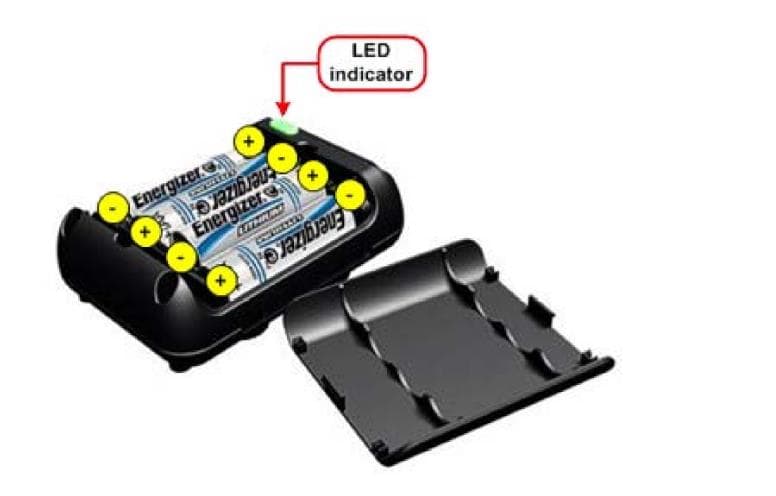
U62-1532
Aug 20, 2020Wireless Pressure Sensor
Equipment Class
DXX - Part 15 Low Power Communication Device Transmitter
U62-1259
Nov 02, 2015Wireless subfloor differential pressure and temperature sensor node.
Equipment Class
DTS - Digital Transmission System
U62-1156
Jan 12, 2014802.15.4 Wireless Intelligent Gateway
Equipment Class
DTS - Digital Transmission System
U62-0944
Aug 19, 2012Thermanode EZ
Equipment Class
DTS - Digital Transmission System
U62-0883
Jul 24, 2012Wireless Damper Controller
Equipment Class
DTS - Digital Transmission System