U62-1156802.15.4 Wireless Intelligent Gateway
SynapSense Corporation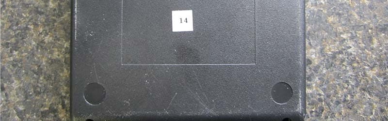
Click to zoom
Application Details
- Equipment Class
- DTS - Digital Transmission System
- Date of Grant
- Jan 12, 2014
- Application Purpose
- Original Equipment
- Date of Application
- Jan 08, 2014
- Equipment Note
- 802.15.4 Wireless Intelligent Gateway
- Frequency Range
- 2405.00000000 - 2480.00000000
- Company
- SynapSense Corporation
- Country
- United States
Documents & Files
Document Text
Text extracted from the exhibit documents filed with the FCC. Open a document above to read the original.
Users Manual
SynapSense Intelligent Gateway Installation Guide December 17, 2013 SynapSense Intelligent Gateway Installation Guide © 2013 SynapSense Corporation. All Rights Reserved This documentation is protected by United States and international copyright and other intellectual and industrial property laws. It is solely owned by SynapSense Corporation and its licensors and is distributed under a restrictive license. This product, or any portion thereof, may not be used, copied, modified, reverse assembled, reverse compiled, reverse engineered, distributed, or redistributed in any form by any means without the prior written authorization of SynapSense Corporation. RESTRICTED RIGHTS: Use, duplication, or disclosure by the U.S. Government is subject to restrictions of FAR 52.227-14(g) (2)(6/87) and FAR 52.227-19(6/87), or DFAR 252.227-7015 (b)(6/95) and DFAR 227.7202-3(a), and any and all similar and successor legislation and regulation. SynapSense Corporation 340 Palladio Parkway, Suite 530 Folsom, CA 95630-8598 Tel: (916) 294-0110 Fax: (916) 294-0270 www.SynapSense.com SynapSense Intelligent Gateway Installation Guide December 17, 2013 ii Trademarks SynapSense®, the SynapSense logo and SynapSoft™ are registered trademarks or trademarks of SynapSense Corporation. Additional trademark applications are pending for SynapSense Active Control™, P 3 SmartPlug™, LiveImaging™, PowerImaging™, SmartLink™. All third-party brand and product names are the trademarks of their respective owners and are used solely for informational purposes. Disclaimer This documentation is provided “as is” without warranty of any kind, either expressed or implied, including but not limited to, the implied warranties of merchantability or fitness for a particular purpose. This documentation might include technical inaccuracies or other errors. Corrections and improvements might be incorporated in new versions of the documentation. SynapSense does not assume any liability arising out of the application or use of any products or services and specifically disclaims any and all liability, including without limitation consequential or incidental damages. SynapSense products are not designed for use in life support appliances, devices, or other systems where malfunction can reasonably be expected to result in significant personal injury to the user, or as a critical component in any life support device or system whose failure to perform can be reasonably expected to cause the failure of the life support device or system, or to affect its safety or effectiveness. SynapSense customers using or selling these products for use in such applications do so at their own risk and agree to fully indemnify and hold SynapSense and its officers, employees, subsidiaries, affiliates, and distributors harmless against all claims, costs, damages, and expenses, and reasonable attorney fees arising out of, directly or indirectly, any claim of personal injury or death associated with such unintended or unauthorized use, even if such claim alleges that SynapSense was negligent regarding the design or manufacture of its products. SynapSense reserves the right to make corrections, modifications, enhancements, improvements, and other changes to its products or services at any time and to discontinue any product or service without notice. Customers should obtain the latest relevant information before placing orders and should verify that such information is current and complete. All products are sold subject to SynapSense Corporation's terms and conditions of sale supplied at the time of order acknowledgment or sale. SynapSense does not warrant or represent that any license, either express or implied, is granted under any SynapSense patent right, copyright, mask work right, or other SynapSense intellectual property right relating to any combination, machine, or process in which SynapSense products or services are used. Information published by SynapSense regarding third-party products or services does not constitute a license from SynapSense to use such products or services or a warranty or endorsement thereof. Use of such information may require a license from a third party under the patents or other intellectual property of the third party, or a license from SynapSense under the patents or other intellectual property of SynapSense. SynapSense Intelligent Gateway Installation Guide December 17, 2013 iii Regulatory Information Notice to Users: This equipment has been tested and found to comply with the limits for Class B digital device, pursuant to Part 15 of the FCC rules. These limits are designed to provide reasonable protection against harmful interference in a residential installation. This equipment generates, uses, and can radiate radio frequency energy and, if not installed and used in accordance with the instructions, may cause harmful interference to radio communications. However, there is no guarantee that interference will not occur in a particular installation. If the equipment does cause harmful interference to radio or television reception, which can be determined by turning the equipment off and on, the user is encouraged to try to correct the interference by one or more of the following measures: • Reorient or relocate the receiving antenna. • Increase the separation between the equipment and the receiver. • Plug the equipment into an outlet on a circuit different from that which the receiver is plugged. • Consult the dealer or an experienced radio/TC technician for help. This product works using a radio frequency, so use on an airplane may be restricted due to interference. FCC Statement: This device complies with part 15 of the FCC Rules. Operation is subject to the following two conditions: (1) This device may not cause harmful interference, and (2) this device must accept any interference received, including interference that may cause undesired operation. Changes or modifications not expressly approved by the party responsible for complianc…
Text truncated - open the document above for the full version.
ID Label/Location Info
MODEL: 1156FCC ID: U62-1156IC: 7265A-1156 PART NUMBER: 99-1156-001 PRYYWWZZZZXX
ID Label/Location Info
EXPLODED TRIMETRIC VIEW 6 4 5 2 1 3 ISOMETRIC VIEW BOTTOM VIEW 7 ITEM NO.DESCRIPTIONQTY. 1PCBA, YODA1 2NYLON UNTHREADED SPACER, 3-16" OD, 1/4" LENGTH, #4 SCREW SIZE4 3SCREW, 4-20 X 1/4" PAN HEAD, ZINC PLATED STEEL, T10 DRIVE (RoHS COMP)4 4CLIP, ZIP TIE MOUNTING, PANEL MOUNT, BLACK (RoHS)4 5SCREW, LARGE DIAMETER PAN HEAD, #4 X 3/4" SHEET METAL (RoHS)4 6CASE, YODA1 7LABEL, PRINTED, REGULATORY/MODEL NUMBER, 2X1.5" (ROHS COMP)1 REVISIONS REV.FAB CAD FILENATIVE DRAWING FILENATIVE CAD FILEDESCRIPTIONDATEAPPROVED A88-1231-001-A.PDF88-1231-001-A.SLDDRW99-1156-001-A.SLDASMINITIAL PROTOTYPE RELEASE.12/17/2013KD/LB D C B A A B C D 12 3 45 6 7 8 8 7 6 5 4 3 2 1 E F E F A D SIZE DRAWN BY DWG. NO. DATE 12/17/13 REVISION TOLERANCES APPROVED DATE 12/17/13 DATE 12/17/13 12/17/13 CHECKED K. Dills PROPRIETARY AND CONFIDENTIAL DATE SCALE: 1:1 ENGINEER WEIGHT: SHEET 1 OF 1 TITLE: See Notes K. Dills THIRD ANGLE PROJECTION L. Brown D. Tostenson Synapsense CUSTOMER YODA PROGRAM NAME NEXT ASSEMBLY 88-1231-001 ASSEMBLY DRAWING, YODA 340 Palladio Pkwy, Suite 540 Folsom, CA 95630 Tel. 916 294-0110 Fax 916 294-0270 www.synapsense.com THE INFORMATION CONTAINED IN THIS DRAWING IS THE SOLE PROPERTY OF SYNAPSENSE CORPORATION ANY REPRODUCTION IN PART OR AS A WHOLE WITHOUT THE WRITTEN PERMISSION OF SYNAPSENSE CORPORATION IS PROHIBITED.
RF Exposure Info
Page 1 of 8 Report No: 94614-18 RADIO FREQUENCY EXPOSURE REPORT FOR THE SynapSense Intelligent Gateway Model: 1156 Report No.: 94614-18 Date of issue: November 18, 2013 PREPARED FOR: Abraham Fechter SynapSense Corporation 340 Palladio Parkway, Suite 540 Folsom, CA 95630 PREPARED BY: Chuck Kendall CKC Laboratories, Inc. 5046 Sierra Pines Drive Mariposa, CA 95338 The test data contained in this report documents the observed testing parameters pertaining to and are relevant for only the sample equipment tested in the agreed upon operational mode(s) and configuration(s) as identified herein. Compliance assessment remains the client’s responsibility. This report may not be used to claim product endorsement by A2LA or any government agencies. This test report has been authorized for release under quality control from CKC Laboratories, Inc. Steve Behm Director of Quality Assurance & Engineering Services CKC Laboratories, Inc. Page 2 of 8 Report No: 94614-18 The following device was tested by CKC Laboratories: Intelligent Gateway. Since the time of testing the manufacturer has chosen to use the following device name in its place: SynapSense Intelligent Gateway. Any differences between the names do not affect their EMC characteristics and therefore meets the level of testing equivalent to the tested model name shown on the data sheets: Intelligent Gateway. Purpose: To demonstrate compliance with United States, Canada and/or European Union RF Exposure requirements for Portable equipment (devices used ≤20cm from the body) or Mobile equipment (devices used >20cm from the body) with power output below exemption levels and Mobile equipment, where Maximum Permissible Exposure (MPE) Calculations apply. United States Compliance Requirements (1.1310): RF Exposure Evaluation Limits Occupational / Controlled Exposure Frequency Range (MHz) Electric Field Strength (V/m) Magnetic Field Strength (A/m) Power Density (mW/cm 2 ) Averaging Time (minutes) 0.3-3.0 614 1.63 *(100) 6 3.0-30 1842/f 4.89/f *(900/f 2 ) 6 30-300 61.4 0.163 1 6 300-1500 --- --- f/300 6 1500-100,000 --- --- 5.0 6 RF Exposure Evaluation Limits General Population / Uncontrolled Exposure Frequency Range (MHz) Electric Field Strength (V/m) Magnetic Field Strength (A/m) Power Density (mW/cm 2 ) Averaging Time (minutes) 0.3-1.34 614 1.63 *(100) 30 1.34-30 824/f 2.19/f *(180/f 2 ) 30 30-300 27.5 0.073 0.2 30 300-1500 --- --- f/1500 30 1500-100,000 --- --- 1.0 30 * Plane wave equivalent power density Limit is calculated based on the mid-band frequency used in the operating frequency range. Exemption Level: Power output <60/f GHz (mW) Page 3 of 8 Report No: 94614-18 Canadian Compliance Requirements (RSS-102): RF Exposure Evaluation Limits Occupational / Controlled Exposure: Frequency Range (MHz) Electric Field Strength (V/m) Magnetic Field Strength (A/m) Power Density (W/m 2 ) Averaging Time (minutes) 0.003-1.0 600 4.9 --- 6 1.0-10 600/f 4.9/f --- 6 10-30 60 4.9/f --- 6 30-300 60 0.163 10 6 300-1500 3.54 f 0.5 0.0094*f 0.5 f/3 6 1500-15,000 137 0.364 50 6 15,000-150,000 137 0.364 50 616000/f 1.2 RF Exposure Evaluation Limits General Population / Uncontrolled Exposure Frequency Range (MHz) Electric Field Strength (V/m) Magnetic Field Strength (A/m) Power Density (W/m 2 ) Averaging Time (minutes) 0.003-1.0 280 2.19 --- 6 1.0-10 280/f 2.19/f --- 6 10-30 28 2.19/f --- 6 30-300 28 0.073 2 6 300-1500 1.585 * f 0.5 0.0042 * f 0.5 f/150 6 1500-15,000 61.4 0.163 10 6 15,000-150,000 61.4 0.163 10 616000/f 1.2 *Power density limit applicable >100MHz Exemption Level: Frequency Range (MHz) Maximum Output Power (Conducted or EIRP) 0.003-1000 ≤ 200 mW 1000-2200 ≤ 100 mW 2200-3000 ≤ 20 mW 3000-6000 ≤ 10 mW Page 4 of 8 Report No: 94614-18 European Union Compliance Requirements (ICNIRP): RF Exposure Evaluation Limits Occupational / Controlled Exposure: Frequency Range (MHz) Electric Field Strength (V/m) Magnetic Field Strength (A/m) Power Density (W/m 2 ) Averaging Time (minutes) 0.00082-0.065 610 24.4 --- 6 0.065-1.0 610 1.6/f --- 1.0-10 610/f 1.6/f --- 6 10-400 61 0.16 10 6 400-2000 3.0 * f 0.5 0.008 * f 0.5 f/40 6 2000-300,000 137 0.36 50 6 RF Exposure Evaluation Limits General Population / Uncontrolled Exposure Frequency Range (MHz) Electric Field Strength (V/m) Magnetic Field Strength (A/m) Power Density (W/m 2 ) Averaging Time (minutes) 0.003-0.150 87 5.0 --- 6 0.150-1.0 87 0.73/f -- 6 1.0-10 87/f 0.5 0.73/f --- 6 10-400 28 0.073 2 6 400-2000 1.375 f 0.5 0.0037*f 0.5 f/200 6 2000-300,000 61 0.16 10 6 *Power density limit applicable >100MHz Exemption Level: Power output < 20mW 1 Page 5 of 8 Report No: 94614-18 Device and Antenna Operating Configuration: Device operating at maximum output power with continuous transmission of modulated data. Orientated in table/wall mounted position as intended, the EUT is placed on the wooden table lined with Styrofoam of 10 cm thickness. The IO cables and AC/DC power cables are routed in as designed. IO cables are unterminated. The EUT is set in constant transmit mode at the rated power. The Support AC step-down transformer is remotely located. Antenna gain = 3.3 dBi Modulation: O-QPSK , Protocol: Zigbee (802.15) Freq: 2400-2483.5MHz Test Procedure: This equipment is evaluated in accordance with the guidelines set forth in OET Guide 65 & ANSI C95.1 for the US and Health Canada Safety Code 6 & RSS 102 for Canada. Other Considerations: None Page 6 of 8 Report No: 94614-18 MPE Calculations Applicability: Limit Used X General Population / Uncontrolled Exposure Occupational / Controlled Exposure RF Exposure Exemption Yes United States Yes Canada Yes Europe Equipment operational details: Config # Operating Frequency (MHz) Measured Output Power (dBm) Antenna Gain (dBi) Antenna Type / Configuration EIRP (dBm) 1 2405 2.2 3.3 integral 5.5 Measurements based from EMC Test Report(s): 94614-9 & 94614-11 MPE Calculation: 2 4d EIRP DensityPower Given: EIRP in mW or W and d in cm or m Config # Distance (cm) US (1.1310) Canada (RSS-102) EU (…
Text truncated - open the document above for the full version.
Test Report
This report contains a total of 60 pages and may be reproduced in full only. Partial reproduction may only be done with the written consent of CKC Laboratories, Inc. SynapSense Corporation ADDENDUM TO TEST REPORT 94614-9 SynapSense Intelligent Gateway Model: 1156 Tested To The Following Standards: FCC Part 15 Subpart C Sections 15.207, 15.247 and RSS-210 Issue 8 Report No.: 94614-9A Date of issue: January 7, 2014 This test report bears the accreditation symbol indicating that the testing performed herein meets the test and reporting requirements of ISO/IEC 17025 under the applicable scope of EMC testing for CKC Laboratories, Inc. We strive to create long-term, trust based relationships by providing sound, adaptive, customer first testing services. We embrace each of our customers’ unique EMC challenges, not as an interruption to set processes, but rather as the reason we are in business. Page 2 of 60 Report No.: 94614-9A TABLE OF CONTENTS Administrative Information ........................................................................................................................................... 3 Test Report Information ............................................................................................................................................ 3 Revision History ......................................................................................................................................................... 3 Report Authorization ................................................................................................................................................. 3 Test Facility Information ............................................................................................................................................ 4 Software Versions ...................................................................................................................................................... 4 Site Registration & Accreditation Information .......................................................................................................... 4 Summary of Results ................................................................................................................................................... 5 Conditions During Testing.......................................................................................................................................... 5 Equipment Under Test ............................................................................................................................................... 6 Peripheral Devices ..................................................................................................................................................... 6 FCC Part 15 Subpart C .................................................................................................................................................... 7 15.207 AC Conducted Emissions ................................................................................................................................ 7 15.247(a)(2) -6dB Occupied Bandwidth .................................................................................................................. 15 RSS-210 A8.2 (a) Emissions Bandwidth Measurements .......................................................................................... 19 15.247(b) (3) RF Power Output ................................................................................................................................ 25 15.247(d) Radiated Spurious Emissions ................................................................................................................... 29 15.247(b) Band Edge ................................................................................................................................................ 51 15.247(e) Peak Power Spectral Density ................................................................................................................... 55 Supplemental Information .......................................................................................................................................... 59 Measurement Uncertainty ...................................................................................................................................... 59 Emissions Test Details .............................................................................................................................................. 59 Page 3 of 60 Report No.: 94614-9A ADMINISTRATIVE INFORMATION Test Report Information REPORT PREPARED FOR: REPORT PREPARED BY: SynapSense Corporation 340 Palladio Parkway, Suite 540 Folsom, CA 95630 Dianne Dudley CKC Laboratories, Inc. 5046 Sierra Pines Drive Mariposa, CA 95338 Representative: Abraham Fechter Project Number: 94614 Customer Reference Number: 451273 DATE OF EQUIPMENT RECEIPT: October 21, 2013 DATE(S) OF TESTING: October 21 – November 5, 2013 December, 16, 2013 Revision History Original: Testing of the SynapSense Intelligent Gateway, Model: 1156 to FCC Part 15 Subpart C Sections 15.207, 15.247and RSS-210 Issue 8. Addendum A: To insert corrected data for sections RSS-210 A8.2(a) Emissions Bandwidth, FCC 15.247(b)(3) Power Output and 15.247(e) Peak Power Spectral Density. Report Authorization The test data contained in this report documents the observed testing parameters pertaining to and are relevant for only the sample equipment tested in the agreed upon operational mode(s) and configuration(s) as identified herein. Compliance assessment remains the client’s responsibility. This report may not be used to claim product endorsement by A2LA or any government agencies. This test report has been authorized for release under quality control from CKC Laboratories, Inc. Steve Behm Director of Quality Assurance & Engineering Services CKC Laboratories, Inc. Page 4 of 60 Report No.: 94614-9A Test Fac…
Text truncated - open the document above for the full version.
Test Setup Photos
Low Frequency Middle Frequency High Frequency
Contact Information
Applicant
Jeffery Fitch(Senior Product Manager)
Technical Contact
SynapSenseAbraham Fechter
[email protected]916-293-0930
340 Palladio Pkwy · Folsom, California · United States
Test Firm
CKC Laboratories, Inc.Steve Behm
Technical Specifications
| # | Rule Parts | Frequency Range | Power Output |
|---|---|---|---|
| 1 | 15C | 2.40 GHz - 2.48 GHz | 1.70 mW |
Other Applications from SynapSense Corporation
U62-1532
Aug 20, 2020Wireless Pressure Sensor
Equipment Class
DXX - Part 15 Low Power Communication Device Transmitter
U62-1259
Nov 02, 2015Wireless subfloor differential pressure and temperature sensor node.
Equipment Class
DTS - Digital Transmission System
U62-0944
Aug 19, 2012Thermanode EZ
Equipment Class
DTS - Digital Transmission System
U62-0883
Jul 24, 2012Wireless Damper Controller
Equipment Class
DTS - Digital Transmission System
U62-SJA100
Aug 24, 2011SynapSense P3 SmartPlug Power Meter in data center server cabinets
Equipment Class
DTS - Digital Transmission System