U62-1532Wireless Pressure Sensor
SynapSense Corporation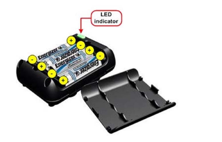
Click to zoom
Application Details
- Equipment Class
- DXX - Part 15 Low Power Communication Device Transmitter
- Date of Grant
- Aug 20, 2020
- Application Purpose
- Original Equipment
- Date of Application
- Aug 20, 2020
- Equipment Note
- Wireless Pressure Sensor
- Frequency Range
- 2405.00000000 - 2480.00000000
- Company
- SynapSense Corporation
- Country
- United States
Documents & Files
Document Text
Text extracted from the exhibit documents filed with the FCC. Open a document above to read the original.
Users Manual
Pressure Node Installation Manual Release 7.4.1 Issue 1 1 Contents Overview ......................................................................................................................... 3 About this Installation Guide ............................................................................................ 4 Organization ................................................................................................................ 4 Document Conventions ............................................................................................... 5 Document References ................................................................................................. 5 Compliance Notice ....................................................................................................... 5 Warnings and Precautions .............................................................................................. 7 Getting Started ................................................................................................................ 8 Required Hardware ...................................................................................................... 8 Required Software ....................................................................................................... 9 Required Tools and Materials ...................................................................................... 9 Installing Pressure Nodes ............................................................................................. 10 General Installation Guidelines .................................................................................. 10 Installation Process Flow ........................................................................................... 10 Preparing to Install the Pressure Node Hardware ......................................................... 11 Pressure Node Placement ......................................................................................... 11 Installing Pressure Node Kits ........................................................................................ 12 Cabinet/Floor to Subfloor ....................................................................................... 13 Overhead Plenum Installation ................................................................................ 13 Cabinet and Subfloor Installation ............................................................................... 14 Overhead Plenum Installation .................................................................................... 17 Replacing an Existing Pressure Node 2 with a New Pressure Node 3 .......................... 19 Validating and Commissioning the Pressure Node Installation ..................................... 20 Pressure Node LED Status Lights ............................................................................. 21 Pressure Node 2 .................................................................................................... 21 Pressure Node 3 .................................................................................................... 23 Inspecting the Installation .............................................................................................. 24 PRESSURE NODE INSTALLATION MANUAL 2 Appendix A – Maintenance ........................................................................................... 25 Battery Replacement ................................................................................................. 25 Removing a Pressure Node Diffuser Hose ................................................................ 25 Appendix B – Environmental Monitoring System Commissioning Form ........................ 27 FRM-007 Environmental Monitoring System ............................................................. 27 Appendix C – Technical Support and Return Material Authorization ............................. 35 Panduit Technical Support ......................................................................................... 35 Opening a Technical Support Case ....................................................................... 35 Return Material Authorization .................................................................................... 36 Returning SynapSense Products ........................................................................... 36 What Happens Next? ............................................................................................. 37 PRESSURE NODE INSTALLATION MANUAL 3 Overview A Pressure Node is a wireless node that measures air pressure differences between the data center room and its subfloor cavities or overhead plenum environments. A Pressure Node installation kit consists of the wireless pressure-sensing node and two low-pressure air hoses fitted with diffusers. Each diffuser resides in a location to measure the air pressure differential between the room and the subfloor or overhead plenums. Once installed and operational, the node transmits air pressure data to the Web Console. Combined with other air pressure differential data collected from various locations in the data center, operators use this information to adjust fan speeds and relocate perforated tiles to increase CRAC/CRAH efficiency. PRESSURE NODE INSTALLATION MANUAL 4 About this Installation Guide This document provides guidelines and instructions for installing SynapSense® Pressure Node kits to designated service companies or the customer. The intended audience for this document consists of customers or partners of SynapSense Corporation, SynapSense installers, and SynapSense installation teams. SynapSense “Tier 1” training is highly recommended for installation engineers and others who are installing SynapSense hardware or closely involved with the installation of data center optimization equipment. Organization This installation guide describes the tasks for installing Pressure Nodes. Table 1 lists the …
Text truncated - open the document above for the full version.
Cover Letter(s)
August 13, 2020 Nemko Canada Inc. 303 River Road Ottawa, ON Canada K1V 1H2 REQUEST FOR CONFIDENTIALITY Name of Applicant: SynapSense a Panduit Company Address: 340 Palladio Parkway, Suite 530 City: Folsom, CA Country: USA FCC ID: U62-1532 IC ID: 7265A-1532 Pursuant to Sections 0.457(d) and 0.459 of the commission’s rules and Industry of Canada Regulations, we hereby request that the following documents be held under confidentiality. LONG TERM: 1. Block diagrams 2. Operational description 3. Schematics 4. Parts List The above information contains trade secrets and proprietary information not customarily released to the public. The public disclosure of this information might be harmful to the applicant and provide unjustified benefits to its competitors. Dated: 2020-07-21 Signed: Printed: Jeffery Fitch Title: Group Products Manager
External Photos
EXTERNAL PHOTOS OF EUT Bottom Top Right Side Back Left Side Front Top off
ID Label/Location Info
THIS COPY IS PROVIDED ON A RESTRICTED BASIS AND IS NOT TO BE USED IN ANY WAY DETRIMENTAL TO THE INTERESTS OF PANDUIT CORP. A B A B 12 21 D10100DA/20 01661NAJ/00 01661NAJ_DS/00A 00A08/14/2019PJSTABFRRODRELEASE TO PRODUCTION01661NAJ REVDATEBYCHKAPRDESCRIPTIONECN PRODUCT SPECPACKAGING SPEC N/AN/A PART NUMBERWORK INSTRUCTION 01661NAJN/A INSPECTION INSTRUCTION NUMBERFMEA & CONTROL PLAN NUMBER N/AN/A TITLE SYNAPSENSE PRESSURE NODE COMPLIANCE / PART LABEL CONTROL DRAWING ITEM REVISION NAME DATASET FILE NAME MATERIAL: UNLESS OTHERWISE SPECIFIED, DIMENSIONAL TOLERANCES ARE: mm [IN] 60-0339-101 .X .XXX .XX ANGLES DRAWING NUMBER: THIRD ANGLE PROJECTION 01661NAJ_DS DRAWN BYDATECHKSCALE SIZE PJST08/14/20191:1SHT 1 OF 1 A 50.8 2.00 38.1 1.50 NOTES: 1. IDENTIFICATION: SYNAPSENSE PRESSURE NODE COMPLIANCE / PART LABEL 2. COLOR: A. BACKGROUND: WHITE B. TEXT: BLACK, ARIAL 6 POINT 3. AFTER PRINTING, VERIFY TEXT DOES NOT SMEAR/RUB 4. APPLY SYNAPSENSE AND OTHER LOGO'S PER FILES PROVIDED. 5. SERIAL NUMBER AND HUMAN READABLE BARCODE: FONT: BLACK, ARIAL 6 POINT LL = MANUFACTURING LOCATION (PR = PRIDE) YY = YEAR (2019 = 19) WW = WORK WEEK (ASSIGNED PER MANUFACTURER CALENDAR) ZZZZ = SEQUENTIALLY ASSIGNED NUMBER (HEX-DECIMAL 0-F) XX = PRODUCT CODE (P3) 6. LOGOS MUST BE 5mm (0.2in) HEIGHT MINIMUM 7. SEE PART NUMBER 01661NAJ IN ARENA FOR ALL OTHER COMPLIANCE LABEL SPECIFICATIONS Label Location
ID Label/Location Info
THIS COPY IS PROVIDED ON A RESTRICTED BASIS AND IS NOT TO BE USED IN ANY WAY DETRIMENTAL TO THE INTERESTS OF PANDUIT CORP. A B A B 12 21 D10100DA/20 01661NAJ/00 01661NAJ_DS/00A 00A08/14/2019PJSTABFRRODRELEASE TO PRODUCTION01661NAJ REVDATEBYCHKAPRDESCRIPTIONECN PRODUCT SPECPACKAGING SPEC N/AN/A PART NUMBERWORK INSTRUCTION 01661NAJN/A INSPECTION INSTRUCTION NUMBERFMEA & CONTROL PLAN NUMBER N/AN/A TITLE SYNAPSENSE PRESSURE NODE COMPLIANCE / PART LABEL CONTROL DRAWING ITEM REVISION NAME DATASET FILE NAME MATERIAL: UNLESS OTHERWISE SPECIFIED, DIMENSIONAL TOLERANCES ARE: mm [IN] 60-0339-101 .X .XXX .XX ANGLES DRAWING NUMBER: THIRD ANGLE PROJECTION 01661NAJ_DS DRAWN BYDATECHKSCALE SIZE PJST08/14/20191:1SHT 1 OF 1 A 50.8 2.00 38.1 1.50 NOTES: 1. IDENTIFICATION: SYNAPSENSE PRESSURE NODE COMPLIANCE / PART LABEL 2. COLOR: A. BACKGROUND: WHITE B. TEXT: BLACK, ARIAL 6 POINT 3. AFTER PRINTING, VERIFY TEXT DOES NOT SMEAR/RUB 4. APPLY SYNAPSENSE AND OTHER LOGO'S PER FILES PROVIDED. 5. SERIAL NUMBER AND HUMAN READABLE BARCODE: FONT: BLACK, ARIAL 6 POINT LL = MANUFACTURING LOCATION (PR = PRIDE) YY = YEAR (2019 = 19) WW = WORK WEEK (ASSIGNED PER MANUFACTURER CALENDAR) ZZZZ = SEQUENTIALLY ASSIGNED NUMBER (HEX-DECIMAL 0-F) XX = PRODUCT CODE (P3) 6. LOGOS MUST BE 5mm (0.2in) HEIGHT MINIMUM 7. SEE PART NUMBER 01661NAJ IN ARENA FOR ALL OTHER COMPLIANCE LABEL SPECIFICATIONS
Internal Photos
Internal Pictures TOP Bottom and Case
RF Exposure Info
ONE WORLD OUR APPR OVAL www.nemko.com KDB 447498 D01 General RF Exposure Guidance v05r02 (February 7, 2014) 1. Declaration of RF exposure compliance for exemption from routine evaluation limits FCC ID: U62-1532 Model number: 1532 Manufacturer: SynapSense a Panduit Company 4.3.1. Standalone SAR test exclusion considerations: During normal operation, user extremities can come within 20 cm of the internal antenna and therefore product is considered as “Portable”. The 1-g and 10-g SAR test exclusion thresholds for 100 MHz to 6 GHz at Test separation distances ≤ 50 mm are determined by: [(max. power of channel, including tune-up tolerance, mW) ÷ (min. test separation distance, mm)] × [ √ 퐹(퐺퐻푧)] ≤ 3.0 for 1-g SAR and ≤ 7.5 for 10-g extremity SAR, where f(GHz) is the RF channel transmit frequency in GHz Power and distance are rounded to the nearest mW and mm before calculation The result is rounded to one decimal place for comparison The test exclusions are applicable only when the minimum test separation distance is ≤ 50 mm and for transmission frequencies between 100 MHz and 6 GHz. When the minimum test separation distance is < 5 mm, a distance of 5 mm according to 5) in section 4.1 is applied to determine SAR test exclusion Calculation based on the above formula: Separation Distance = 5 mm Radiated Output Power = -7.03 dBm = 0.198 mW Frequency = 2445 GHz Calculation = (0.198÷5)× √ 2.445 = 0.06 < 3 The calculation is below the threshold, therefore the product exempt from the SAR test requirements 2. Attestation ATTESTATION: I attest that the testing was performed or supervised by me; that the test measurements were made in accordance with the above-mentioned departmental standard(s), and that the radio equipment identified in this application has been subject to all applicable test conditions specified in the departmental standards and all of the requirements of the standards have been met. Signature: Date: August 11, 2020 Name: Chip Fleury FCC RF Exemption letter
Test Report
Report reference ID: 386816 – 1TRFWL Page 1 of 33 ONE WORLDOURAPPROVAL Test report 386816 - 1TRFWL Date of issue: November 19, 2019 Applicant: Panduit Product: Pressure Node 3 Models: 1532 Variants: N/A FCC ID: U62-1532 IC ID: 7265A-1532 Specifications: FCC 47 CFR Part 15.249 Operation within the bands 902–928 MHz, 2400–2483.5 MHz, 5725–5875 MHZ, and 24.0–24.25 GHz. RSS-210 Issue 10, December 2019 Annex B.10 License-Exempt Radio Apparatus: Category 1 Equipment Report reference ID: 386816 – 1TRFWL Page 2 of 33 Test location Company name Nemko USA, Inc. Address 2210 Faraday Ave, Suite 150 City Carlsbad Province California Postal code 92008 Country USA Telephone +1 760 444 3500 Website www.nemko.com Tested by Andre Martinez, Test Engineer. Reviewed by Chip Fleury Date December 9, 2019 Signature Limits of responsibility Note that the results contained in this report relate only to the items tested and were obtained in the period between the date of initial receipt of samples and the date of issue of the report. This test report has been completed in accordance with the requirements of ISO/IEC 17025. All results contain in this report are within Nemko USA’s ISO/IEC 17025 accreditation. This report must not be used by the client to claim product certification, approval, or endorsement by NVLAP, NIST, or any agency of the U.S. Government Copyright notification Nemko USA Inc. authorizes the applicant to reproduce this report provided it is reproduced in its entirety and for use by the company’s employees only. Any use which a third party makes of this report, or any reliance on or decisions to be made based on it, are the responsibility of such third parties. Nemko USA Inc. accepts no responsibility for damages, if any, suffered by any third party as a result of decisions made or actions based on this report. © Nemko USA Inc. Report reference ID: 386816 – 1TRFWL Page 3 of 33 Table of contents Table of contents .......................................................................................................................................................................................................... 3 Section 1. Report summary ................................................................................................................................................................................. 4 1.1 Applicant and manufacturer ................................................................................................................................................................................................ 4 1.2 Test specifications ................................................................................................................................................................................................................. 4 1.3 Statement of compliance ..................................................................................................................................................................................................... 4 1.4 Exclusions .............................................................................................................................................................................................................................. 4 1.5 Test report revision history .................................................................................................................................................................................................. 4 Section 2. Summary of test results ....................................................................................................................................................................... 5 2.1 FCC Part 15 Subpart C, general requirements test results................................................................................................................................................. 5 2.2 FCC Part 15 Subpart C, intentional radiators test results................................................................................................................................................... 5 2.3 IC RSS-GEN, Issue 5, test results........................................................................................................................................................................................... 5 2.4 IC RSS-210, Issue 10, test results ......................................................................................................................................................................................... 5 Section 3. Equipment under test (EUT) details ..................................................................................................................................................... 6 3.1 Sample information .............................................................................................................................................................................................................. 6 3.2 EUT information .................................................................................................................................................................................................................... 6 3.3 Technical information ........................................................................................................................................................................................................... 6 3.4 Product description and theory of operation ..................................................................................................................................................................... 6 3.5 EUT exercise details .............................................................................................................................................................................................................. 6 3.6 EUT setup picture ..............................................…
Text truncated - open the document above for the full version.
Test Setup Photos
TEST SET UP PICTURES Radiated 30 to 1000 MHz Radiated 1 to 18 GHz Radiated 18 to 26 GHz
Contact Information
Applicant
Jeffery Fitch(Senior Product Manager)
Technical Contact
PanduitAbraham Fechter
[email protected]916-293-0930
340 Palladio Parkway, Suite 530 · Folsom, California · United States
Test Firm
Nemko USA, Inc. - San Diego EMC DivisionJan Blomgren
[email protected]760-444-3500
Technical Specifications
| # | Rule Parts | Frequency Range | Power Output |
|---|---|---|---|
| 1 | 15C | 2.40 GHz - 2.48 GHz | - |
Other Applications from SynapSense Corporation
U62-1259
Nov 02, 2015Wireless subfloor differential pressure and temperature sensor node.
Equipment Class
DTS - Digital Transmission System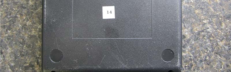
U62-1156
Jan 12, 2014802.15.4 Wireless Intelligent Gateway
Equipment Class
DTS - Digital Transmission System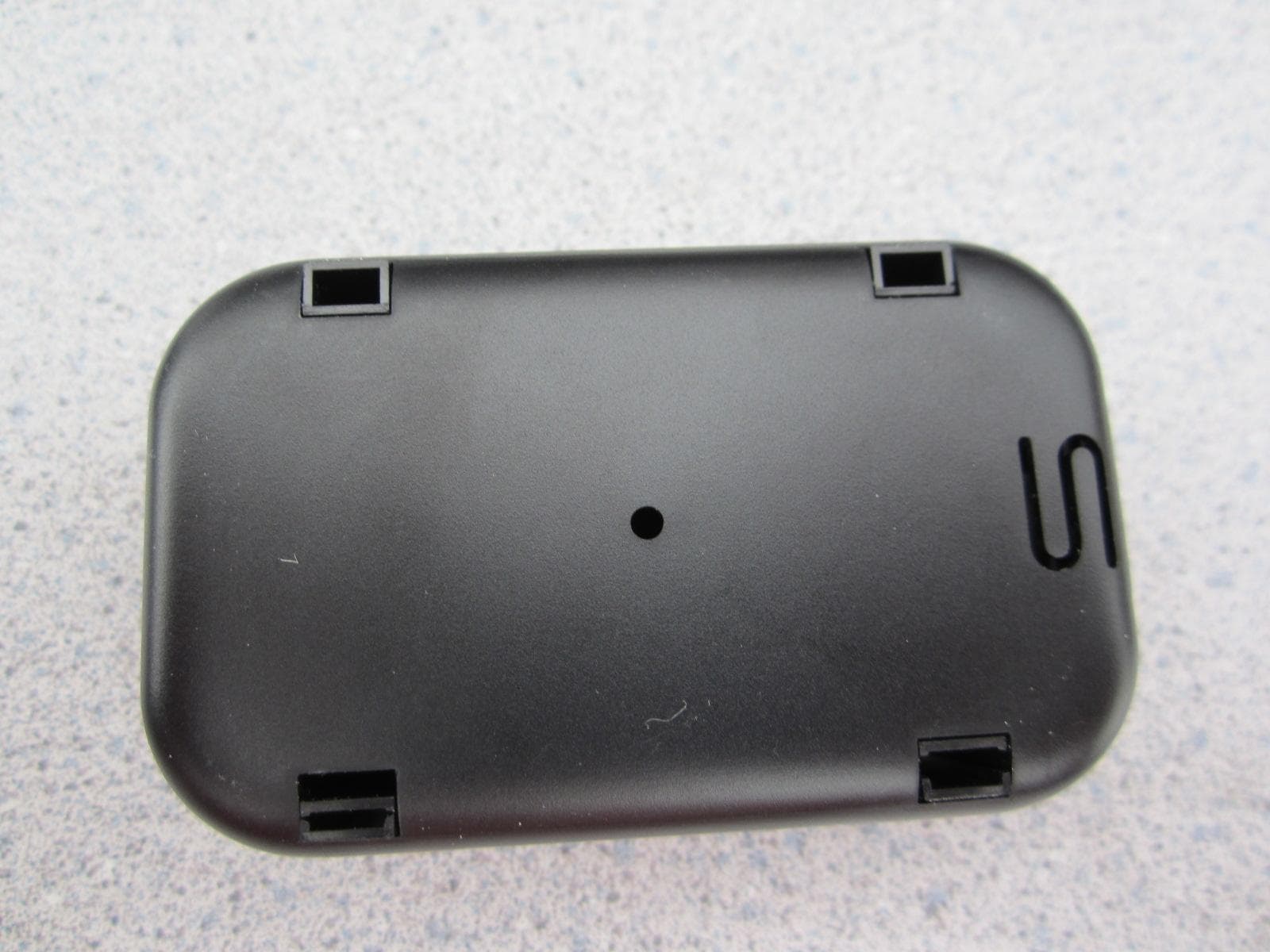
U62-0944
Aug 19, 2012Thermanode EZ
Equipment Class
DTS - Digital Transmission System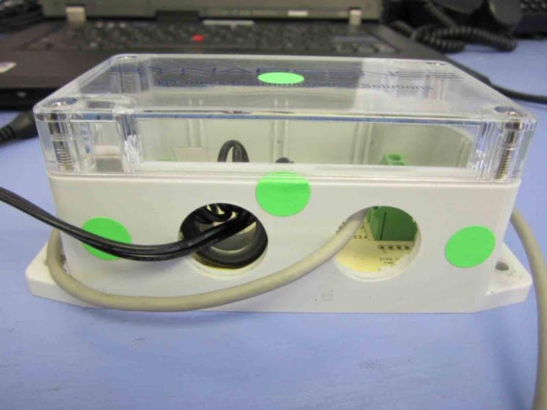
U62-0883
Jul 24, 2012Wireless Damper Controller
Equipment Class
DTS - Digital Transmission System
U62-SJA100
Aug 24, 2011SynapSense P3 SmartPlug Power Meter in data center server cabinets
Equipment Class
DTS - Digital Transmission System