U62-SRA100SynapStamp Radio Module
SynapSense Corporation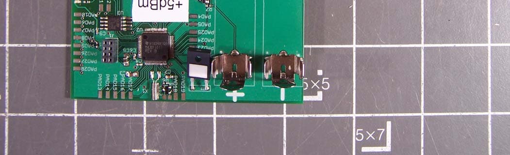
Click to zoom
Application Details
- Equipment Class
- DTS - Digital Transmission System
- Date of Grant
- May 27, 2010
- Application Purpose
- Original Equipment
- Date of Application
- May 17, 2010
- Equipment Note
- SynapStamp Radio Module
- Frequency Range
- 2405.00000000 - 2480.00000000
- Company
- SynapSense Corporation
- Country
- United States
Documents & Files
Document Text
Text extracted from the exhibit documents filed with the FCC. Open a document above to read the original.
Users Manual
2365 Iron Point Rd Suite 100 Folsom CA 95630 Wireless Sensor Network Node Installation and User Manual Document Number 85-0xxx-001 Author Pat Weston Revision Release 1.3 Date May 6, 2010 This manual covers the general installation of the following SynapSense Wireless Sensor Network Nodes: • 99-0039-002 • 99-0039-011 • 99-0039-012 • 99-0039-015 • 99-0189-001 • 99-0217-001 • 99-0331-001 • 99-0348-001 • 99-0360-001 • 11-0606-001* • 11-0606-011* * 11-0606-0xx is a radio module intended for SynapSense use only. Regulatory Information Notice to Users: This equipment has been tested and found to comply with the limits for a Class A digital device, pursuant to Part 15 of the FCC Rules. These limits are designed to provide reasonable protection against harmful interference when the equipment is operated in a commercial environment. This equipment generates, uses, and can radiate radio frequency energy and, if not installed and used in accordance with the instruction manual, may cause harmful interference to radio communications. In addition any modifications not expressly approved by SynapSense Corporation for compliance will void the user’s authority to to operate the equipment. Operation of this equipment in a residential area is likely to cause harmful interference in which case the user will be required to correct the interference at his own expense. Operation is subject to the following two conditions: (1) this device may not cause interference, and (2) this device must accept any interference, including interference that may cause undesired operation of the device. To reduce potential radio interference to other users, the antenna type and its gain should be so chosen that the equivalent isotropically radiated power (e.i.r.p.) is not more than that permitted for successful communication. To protect the user from excessive RF exposure the operator must maintain a safe distance of 20 cm from the device during operation. FCC and Industry Canada Compliance Statement: This device complies with part 15 of the FCC Rules and Industry Canada RSS-210 Rules. Operation is subject to the following two conditions: (1) This device may not cause harmful interference, and (2) this device must accept any interference received, including interference that may cause undesired operation. Changes or modifications not expressly approved by the party responsible for compliance could void the user's authority to operate the equipment. The antenna(s) used for this transmitter must not be co-located or operating in conjunction with any other antenna or transmitter. Antenna Statement: Only the antenna supplied with this unit may be used. Any attempt to modify this antenna or substitute a different antenna by any means shall void the warranty and will void the FCC approval to operate this equipment. In the event an antenna is broken, a replacement antenna may be obtained by contacting the Product Support Center listed in the warranty section of this manual. CE Statement: This equipment has been tested and found to comply with the limits of the European Council Directive on the approximation of the law of the member states relating to electromagnetic compatibility (89/336/EEC) according to EN 55022 Class B. Industry Canada Equipment Notice: The Industry Canada certification identifies certified equipment. This certification means that the equipment meets certain telecommunications network protective, operational and safety requirements as prescribed in the appropriate Terminal Equipment Technical Document(s). The Department does not guarantee the equipment will operate to the user's satisfaction. Before installing this equipment, users should ensure that it is permissible to be connected to the facilities of the local telecommunications company. The equipment must also be installed using an acceptable method of connection. The customer should be aware that compliance with the above conditions may not prevent degradation of service in some situations. Repairs to certified equipment should be coordinated by a representative designated by the supplier. Any repairs or alterations made by the user to this equipment, or equipment malfunctions, may give the telecommunications company cause to request the user to disconnect the equipment. Users should ensure, for their own protection, that the electrical ground connectors of the power utility, telephone lines and internal metallic water pipe system, if present, are connected together. This presentation may be particularly important in rural areas. Caution: Users should not attempt to make such connections themselves, but should contact the appropriate electric inspection authority or electrician, as appropriate. This device has been designed to operate with the antennas listed below, and having a maximum gain of 2.2 dBi. Antennas not included in this list or having a gain greater than 2.2 dBi are strictly prohibited for use with this device. The required antenna impedance is 50 ohms. SynapSense Antenna P/N78-0036-001 Warranty Information Limited One Year Warranty Our company warrants that for two years from the date of purchase, it will replace this product if found to be defective in materials or workmanship. For a prompt, no charge replacement of equivalent product, return the defective product postage prepaid to the appropriate address. Product Support Center 2365 Iron Point Road, Suite 100 Folsom, CA 95630 United States of America This replacement is the company's sole obligation under this warranty. SynapSense, Inc. will not be responsible for any incidental or consequential damages or for any loss arising in connection with the use or inability to use this product. Some states/provinces do not allow the exclusion or limitation of incidental or consequential damages, so the above limitation or exclusion may not apply to you. This warranty excludes defects or damage due to misuse, abuse, or neglect. This warranty gives you specific legal rights, and you may also hav…
Text truncated - open the document above for the full version.
Cover Letter(s)
2365 Iron Point Rd, Suite 100 Folsom, CA USA 95630 T:+1-916-294-0110 F: +1-916-294-0270 5/4/2010 Federal Communications Commission 7435 Oakland Mills Road Columbia, MD 21046 To Whom It May Concern: This letter is to request Limited Modular Approval in accordance with FCC Rule Part 15.212 for the product certified under FCC ID: U62-SRA100. This product is an 802.15.4 compliant radio module and can be used in SynapSense wireless sensor modules. I hereby declare that the following conditions have been met. a. The radio elements of the modular transmitter must have their own shielding. The physical crystal and tuning capacitors may be located external to the shielded radio elements. b. The modular transmitter must have buffered modulation/data inputs (if such inputs are provided) to ensure that the module will comply with part 15 requirements under conditions of excessive data rates or over-modulation. c. The modular transmitter must have its own power supply regulation. d. The modular transmitter must comply with the antenna and transmission system requirements of §§15.203, 15.204(b) and 15.204(c). The antenna must either be permanently attached or employ a “unique” antenna coupler (at all connections between the module and the antenna, including the cable). The “professional installation” provision of §15.203 is not applicable to modules but can apply to limited modular approvals under paragraph (b) of this section. e. The modular transmitter must be tested in a stand-alone configuration, i.e., the module must not be inside another device during testing for compliance with part 15 requirements. Unless the transmitter module will be battery powered, it must comply with the AC line conducted requirements found in §15.207. AC or DC power lines and data input/output lines connected to the module must not contain ferrites, unless they will be marketed with the module (see §15.27(a)). The length of these lines shall be the length typical of actual use or, if that length is unknown, at least 10 centimeters to insure that there is no coupling between the case of the module and supporting equipment. Any accessories, peripherals, or support equipment connected to the module during testing shall be unmodified and commercially available (see §15.31(i)). f. The modular transmitter must be equipped with either a permanently affixed label or must be capable of electronically displaying its FCC identification number. g. The modular transmitter must comply with any specific rules or operating requirements that ordinarily apply to a complete transmitter and the manufacturer must provide adequate instructions along with the module to explain any such requirements. A copy of these instructions must be included in the application for equipment authorization. h. The modular transmitter must comply with any applicable RF exposure requirements in its final configuration. This product is for the exclusive use of SynapSense and is not for resale. This product will be integrated by SynapSense into host configurations as identified below: 1. SynapSense Wireless Sensor Network Node Products 2. SynapSense Wireless Power Monitor Products 3. SynapSense Wireless Gateways I acknowledge on behalf of the applicant that compliance of a module in all final configurations is the responsibility of the applicant under the condition that the integrator follows all required installation instructions. Sincerely, Pat Weston VP Engineering SynapSense Corporation
Cover Letter(s)
2365 Iron Point Rd, Suite 100 Folsom, CA USA 95630 T:+1-916-294-0110 F: +1-916-294-0270 5/18/2010 Federal Communications Commission 7435 Oakland Mills Road Columbia, MD 21046 Gentlemen: This letter is to comply with Section 0.457(d)(2)(i) and Section 0.459 pertaining to confidential material. SynapSense Corporation would like the following documents regarding this submission for FCC ID: U62- SRA100 to be kept confidential. 1. All Schematics 2. All Operational Descriptions 3. All Block Diagrams The above material contains trade secrets or technical data, which would customarily be guarded from competitors. We do not want these documents to be accessible to the general public. Sincerely, Pat Weston VP Engineering SynapSense Corporation 2365 Iron Point Road, Suite 100 Folsom, CA 95630
Cover Letter(s)
2365 Iron Point Rd, Suite 100 Folsom, CA USA 95630 T:+1-916-294-0110 F: +1-916-294-0270 May 18, 2010 To Whom It May Concern: We the undersigned hereby delegate power of attorney to CKC Certification Services, LLC (CKC CS) to act on our behalf in matters of radio equipment certification. CKC CS is appointed as an agent to sign applications before regulatory agency(ies) on our behalf, and to receive and exchange data between our company and the agency(ies). Sincerely, Pat Weston VP Engineering SynapSense Corporation 2365 Iron Point Road, Suite 100 Folsom, CA 95630 916-293-0934
Cover Letter(s)
Non-Conformities FCC ID: U62-SRA100 (CKC CS Ref # E10-000022-FCC-01) The items listed below represent requests for information following review of this application for certification under United S tates (FCC) regulations. Further question may arise pending review of responses to these items. OK ID # Non-Conformity or Comment Subm itted Response Respondent / Date of Response x C 1 The person signing the letter of confidentiality is Pat Weston whereas the person listed on the FCC site as contact is Mathew Di Nicola. In accordance with FCC Policy (KDB 85 2134), please provide all cover letters signed by the authorized individual named in the applicant's grantee code information or by an authorized designee. In the latter case, please also provide letters of authorization signed by the authorized individual designating the alternate(s). In all cases, a paper trail must be demonstrated leading back to the person named under the grantee code. Matt Di Nicola’s signing authority... he is no longer with the company. I am the authorized person at SynapSense. You will need to Update your Grantee Code. Provided Website. Customer Provided FRN Number and asked us to update the Grantee Information. Sent a Note to the Customer that the FRN Number is not needed. What is needed is the Grantee Code Registration Number. And let him know that I would send a request in to the FCC for him. Sent Request to the FCC Asking for the Grantee Code Registration number for Synapsense. Pat Weston 4/5/10 Jessina Hunter 4/5/10 Jessina Hunter 4/8/10 Jessina Hunter 4/8/10 5/3/10;EW, verified Grantee. x C 2 The provide Letter "Modular Approval Request.pdf" requested modular approval for the product. However, the letter did not declare compliance to 15.212 (a) requir ement. Please provide a revised modular approval request letter with declaration to each subpart of 15.212 (a) for full modular approval. Alternatively, a limited modular approval can be granted in accordance with 15. 121(b), in this case pleas e provide a revised letter requesting limited modular approval with inclusion of a statement clarifying how control of the end product into which the module will be installed, will be maintained such that full compliance of the end product is always ensured 5/3/10:Please provide Modular ap proval letter meeting the above requirement, this document is missing from the TEMP folder. Provided Modular Approval Letter. Provided Letter. 5/5/10 EW, ok Pat Weston 4/5/10 Pat Weston 5/4/10 X Report 3 The title page of the test report 90296-14 claims the device was also tested to 15.207, however this device is a battery operate device where 15.207is not app licable and hence not in cluded in the test report. Please provide a revised test report with reference to 15.207 removed. I did not test to 15.207. Updated Report Provided. –CKendall 2 April 2010 Report Department 4/29/10 X L 4 The bottom side of the stamp sized EUT is missing from the internal photograph. Please provide a revised internal photo with the device removed from the support controller board and showing the bottom side of the PCB Photos Provided. –CKendall 2 April 2010 X L 5 The provided external photograph includes a support controller board and the bottom side of the devi ce is hidden from clear view. Please provide a revised exterior photo with the device removed from the support controller board and showing the bottom side of the device. Photos Provided. –CKendall 2 April 2010 X L 6 Page 6 of the test report 90296-14 and the test condition claims the No. The controller card is required for Pat Weston device was not tested with any peripheral devices. However, the setup photographs depicts the device was tested with it installed a support controller board (peripheral) . Please provide a revised test report meeting 2.1033(b)(8) requirement. Alternatively, if the controller card is part of the device seeking certification, then please provide the schematic and block diagram of the device with inclusion of the controller card. testing to provide power and control signals only. 4/5/10 X L 7 Please clarify whether this battery powered device can be operated as portable equipment. For portable equipment, please verify whether the emission profile was maximized by testing in three orthogonal orientations. Neither it is fixed. Similar to a WiFi access point or router. Pat Weston 4/5/10 X Report 8 Page 7 of the test report sec tion 15.31(m) claimed the device operates on single channel; however the test condition demonstrated the number of channel of operation exceeds three. Please provide a revise test report with corrected number of channel to be operated in the assigned frequency band. Yes. There are a total of 83 channels available and we will use most of them in operation. Pat Weston 4/5/10 x L 9 Page 32 of the test report, the frequency of interest is 1- 18GHz, however in accordance with 15 .33, the upper frequency of investigation shall be 10th harmonics of the fundamental or 40 GHz. Please provide a revised test report with frequency range measured up to 10th harmonics of 2480MHz. 5/3/10 : The test condition of page 32 of the test report 90296-14A still list the frequency of interest as 1-18GHz, instead of 10th harmonics of 2480MHz. Please provide a revised test report. 5/5/10; Page 32 of the revised test report indicated the range of measurement is 1 – 25 GHz, however the equipment list may be missing an antenna capable of m easurement up to the declared frequency range. Please confirm whether antenna SN3414 is capable of measurement above 18 GHz, alte rnatively please provide a revised test report with equipment data for measurement in the range 18- 25 Revised Report Provided. Must have missed this page when we did the corrections. Need to change it to read 25 GHz. Revised Report Provided. Report Department 4/29/10 Chuck Kendall 5/4/10 Report Department 5/5/10 MHz. x C 10 Antenna separation distance for RF exposure compliance is missing from the user manual. Pleas p…
Text truncated - open the document above for the full version.
ID Label/Location Info
SynapSense Corporation 2365 Iron Point Road, Suite 100 Folsom, CA 95630 SynapStamp Label Drawing For model: 11-0606-011 Scale 2: 1 Label Placement on Unit A x label to top of unit RF shield, with top of label towards antenna. For 11-0606-011, label will be cut as shown to provide access to RF connector. Label Material: polypropylene or similar plastic Label Adhesive: permanent acrylic Serial Number Model Number Label Contents Revision Mar 4, 2010
RF Exposure Info
Page 1 of 5 Report No:90296-14- R MAXIMUM PERMISSIBLE EXPOSURE REPORT FOR THE SynapStamp Radio Modules FCC ID: U62‐SRA100 IC: 7265A‐SRA100 MODEL NUMBERS: 11-0606-001 & 11-0606-011 DATE OF ISSUE: April 1, 2010 PREPARED FOR: Synapsense Corporation 2365 Iron Point Road, Suite 100 Folsom, CA 95630 PREPARED BY: Chuck Kendall CKC Laboratories, Inc. 5046 Sierra Pines Drive Mariposa, CA 95338 W.O. No.: 90296 P.O. No.: 9742 Report No.: 90296‐14‐R Page 2 of 5 Report No:90296-14- R Purpose of Test: To demonstrate compliance with United States and Canada RF Exposure requirements for Mobile Equipment (devices used >20cm from the body), where Maximum Permissible Exposure (MPE) Calculations apply. United States MPE Limits In Accordance with FCC 1.1310: Occupational / Controlled Exposure Frequency Range (MHz) Electric Field Strength (V/m) Magnetic Field Strength (A/m) Power Density (mW/cm 2 ) Averaging Time (minutes) 0.3‐3.0 614 1.63 *(100) 6 3.0‐30 1842/f 4.89/f *(900/f2) 6 30‐300 61.4 0.163 1 6 300‐1500 ‐‐‐ ‐‐‐ f/300 6 1500‐100,000 ‐‐‐ ‐‐‐ 5 6 General Population / Uncontrolled Exposure Frequency Range (MHz) Electric Field Strength (V/m) Magnetic Field Strength (A/m) Power Density (mW/cm 2 ) Averaging Time (minutes) 0.3‐1.34 614 1.63 *(100) 30 1.34‐30 824/f 2.19/f *(180/f2) 30 30‐300 27.5 0.073 0.2 30 300‐1500 ‐‐‐ ‐‐‐ f/1500 30 1500‐100,000 ‐‐‐ ‐‐‐ 1 30 Note: Limit is calculated based on the mid‐band frequency used in the operating frequency range. Page 3 of 5 Report No:90296-14- R Canadian MPE Limits In Accordance with RSS‐102: Occupational / Controlled Exposure: General Population / Uncontrolled Exposure Page 4 of 5 Report No:90296-14- R Equipment Operational Details: Operating Frequency (MHz) Measured Output Power (dBm) Maximum Mobile Antenna Gain (dBi) Maximum EIRP (dBm) 2480 5.0 2.2 7.2 Measurements based from EMC Test Report: Mariposa Site A,90296, Test Report #: 90296‐14 Device and Antenna Operating Configuration: Device operating at maximum output power with continuous transmission of modulated data. Worst case antenna is 2.2dBi or 1.66 linear Test Procedure: This equipment is evaluated in accordance with the guidelines set forth in OET Guide 65 & ANSI C95.1 for the US and Health Canada Safety Code 6 & RSS 102 for Canada. Other Considerations: None . . MPE Calculations: Limit used: Occupational / Controlled Exposure X General Population / Uncontrolled Exposure MPE Limit =1 (mW/cm 2 ) 2 2 4 )/( d EIRP cmmWDensityPower Given: EIRP in mW and d in cm EIRP (mW) Distance (cm) Power Density (mW/cm 2 ) Limit (mW/cm 2 ) Power Density (W/m 2 ) Limit (W/m 2 ) 5.248 20 0.0010441 1 0.00010441 10 Page 5 of 5 Report No:90296-14- R Statement of Compliance: This device demonstrates compliance under the operating conditions specified in this document. Under normal operating conditions, the antenna is designed to be installed in accordance with the manufacturer’s instructions in such a manor to maintain the minimum separation distance. The MPE calculations shown above demonstrate compliance to the provisions of US and Canadian requirements. As can be seen from the MPE results, this device passes the specified limits at a distance of 20cm at the maximum output power under normal operating conditions.
Test Report
This report contains a total of 71 pages and may be reproduced in full only. Partial reproduction may only be done with the written consent of CKC Laboratories, Inc. Synapsense Corporation ADDENDUM TEST REPORT FOR 90296‐14 SynapStamp Radio Modules, 11‐0606‐001 & 11‐0606‐011 Tested To The Following Standards: FCC Part 15 Subpart C Sections 15.209 & 15.247 and RSS‐210 Version 7 Report No.: 90296‐14A Date of issue: April 28, 2010 TESTING CERT #803.01, 803.02, 803.05, 803.06 This test report bears the accreditation symbol indicating that the testing performed herein meets the test and reporting requirements of ISO/IEC 17025 under the applicable scope of EMC testing for CKC Laboratories, Inc. We strive to create long‐term, trust based relationships by providing sound, adaptive, customer first testing services. We embrace each of our customers’ unique EMC challenges, not as an interruption to set processes, but rather as the reason we are in business. Page 2of 71 Report No.: 90296‐14A TABLE OF CONTENTS Administrative Information .......................................................................................................................... 3 Test Report Information ............................................................................................................................................ 3 Revision History ......................................................................................................................................................... 3 Report Authorization ................................................................................................................................................. 3 Test Facility Information ............................................................................................................................................ 4 Site Registration & Accreditation Information .......................................................................................................... 4 Summary of Results ................................................................................................................................................... 5 Conditions During Testing ......................................................................................................................................... 5 Equipment Under Test ............................................................................................................................................... 6 Peripheral Devices ..................................................................................................................................................... 6 FCC Part 15 Subpart C ................................................................................................................................... 7 Temperature And Humidity During Testing............................................................................................................... 7 15.31(e) Voltage Variation ......................................................................................................................................... 7 15.31(m) Number Of Channels .................................................................................................................................. 7 15.33(a) Frequency Ranges Tested ............................................................................................................................ 7 15.203 Antenna Requirements .................................................................................................................................. 7 EUT Operating Frequency .......................................................................................................................................... 7 15.247 Occupied Bandwidth...................................................................................................................................... 8 15.247b)(3) Peak Power .......................................................................................................................................... 11 15.247(d) Spurious Conducted Emissions ............................................................................................................... 15 15.209/15.247(d) Spurious Radiated Emissions ...................................................................................................... 20 15.247(d) Band Edge................................................................................................................................................ 54 15.247(e) Peak Power Spectral Density ................................................................................................................... 63 RSS‐210 99% Bandwidth .......................................................................................................................................... 66 Supplemental Information .......................................................................................................................... 70 Measurement Uncertainty ...................................................................................................................................... 70 Emissions Test Details .............................................................................................................................................. 70 Page 3of 71 Report No.: 90296‐14A ADMINISTRATIVE INFORMATION Test Report Information REPORT PREPARED FOR: REPORT PREPARED BY: Synapsense Corporation 2365 Iron Point Road, Suite 100 Folsom, CA 95630 Dianne Dudley CKC Laboratories, Inc. 5046 Sierra Pines Drive Mariposa, CA 95338 Representative: Pat Weston Project Number: 90296 Customer Reference Number: 9742 DATE OF EQUIPMENT RECEIPT: February2, 2010 DATE(S) OF TESTING: February2 ‐8, 2010 Revision History Original: To test the SynapStamp Radio Modules, 11‐0606‐001 & 11‐0606‐011 to the standards FCC Part 15 Subpart C Sections 15.207 & 15.247 Addendum …
Text truncated - open the document above for the full version.
Contact Information
Applicant
Jeffery Fitch(Senior Product Manager)
Technical Contact
CKC Certification Serbvices, LLCJessina Hunter
[email protected]209-966-5240
5046 Sierra Pines Dr. · Mariposa · United States
Test Firm
CKC Laboratories, Inc.Steve Behm
Technical Specifications
| # | Rule Parts | Frequency Range | Power Output |
|---|---|---|---|
| 1 | 15C | 2.40 GHz - 2.48 GHz | 3.00 mW |
Other Applications from SynapSense Corporation
U62-1532
Aug 20, 2020Wireless Pressure Sensor
Equipment Class
DXX - Part 15 Low Power Communication Device Transmitter
U62-1259
Nov 02, 2015Wireless subfloor differential pressure and temperature sensor node.
Equipment Class
DTS - Digital Transmission System
U62-1156
Jan 12, 2014802.15.4 Wireless Intelligent Gateway
Equipment Class
DTS - Digital Transmission System
U62-0944
Aug 19, 2012Thermanode EZ
Equipment Class
DTS - Digital Transmission System
U62-0883
Jul 24, 2012Wireless Damper Controller
Equipment Class
DTS - Digital Transmission System