UCE314062ADigital Camera
Panasonic Connect Co., Ltd.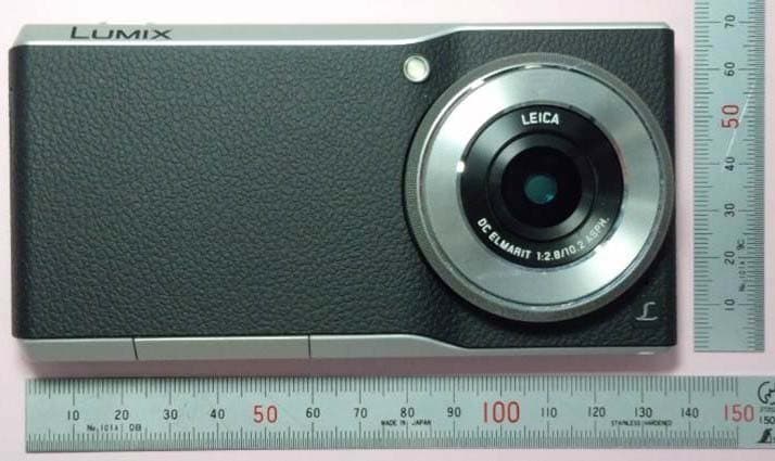
Click to zoom
Application Details
- Equipment Class
- DXX - Part 15 Low Power Communication Device Transmitter
- Date of Grant
- Mar 19, 2015
- Application Purpose
- Original Equipment
- Date of Application
- Mar 19, 2015
- Equipment Note
- Digital Camera
- Frequency Range
- 13.56000000 - 13.56000000
- Company
- Panasonic Connect Co., Ltd.
- Country
- Japan
Documents & Files
Document Text
Text extracted from the exhibit documents filed with the FCC. Open a document above to read the original.
Users Manual
Please read these instructions carefully before using this product, and save this manual for future use. More detailed owner’s manual is available in “Owner’s Manual for advanced features (PDF format)”. To read it, download it from the website. http://panasonic.jp/support/dsc/oi/index.html?model= DMC-CM1&dest=P ≥Click the desired language. ≥You will need Adobe Reader to browse or print the Owner’s Manual (PDF format). You can download and install a version of Adobe Reader that you can use with your OS from the following website. (As of March 2015) http://www.adobe.com/products/acrobat/readstep2.html If you have any questions, visit: USA : www.panasonic.com/support Basic Owner’s Manual Digital Camera Model No. DMC-CM1 SQT0433 F0415MR0 P Register online at www.panasonic.com/register (U.S. customers only) until 2015/04/13 DMC-CM1P-SQT0433_eng.book 1 ページ 2015年3月6日 金曜日 午後1時35分 2 SQT0433 (ENG) Dear Customer, Thank you for choosing Panasonic! You have purchased one of the most sophisticated and reliable products on the market today. Used properly, we’re sure it will bring you and your family years of enjoyment. Please take time to fill in the information below. The serial number is on the tag located on the underside of your camera. Be sure to retain this manual as your convenient camera information source. Please note that the actual controls and components, menu items, etc. of your Digital Camera may look somewhat different from those shown in the illustrations in this Owner’s Manual. Carefully observe copyright laws. ≥Recording of pre-recorded tapes or discs or other published or broadcast material for purposes other than your own private use may infringe copyright laws. Even for the purpose of private use, recording of certain material may be restricted. Date of Purchase Dealer Purchased From Dealer Address Dealer Phone No. Model No. Serial No. DMC-CM1P-SQT0433_eng.book 2 ページ 2015年3月6日 金曜日 午後1時35分 3 (ENG) SQT0433 Information for Your Safety ∫Product identification marking ∫Wi-Fi use ≥This product is restricted to indoor use due to its operation in the 5.15 to 5.25 GHz frequency range. FCC requires this product to be used indoors for the frequency range 5.15 to 5.25 GHz to reduce the potential for harmful interference to co-channel Mobile Satellite systems. High power radars are allocated as primary users of the 5.25 to 5.35 GHz and 5.65 to 5.85 GHz bands. These radar stations can cause interference with and/or damage this product. ≥This transmitter must not be co-located or operated in conjunction with any other antenna or transmitter. ≥The usage of wireless LAN may be restricted depending on the country of use. Check any relevant laws and regulations in the country or the region before use. WARNING: To reduce the risk of fire, electric shock or product damage, ≥Do not expose this unit to rain, moisture, dripping or splashing. ≥Use only the recommended accessories. ≥Do not remove covers. ≥Do not repair this unit by yourself. Refer servicing to qualified service personnel. The socket outlet shall be installed near the equipment and shall be easily accessible. ProductLocation Digital CameraIn the card slot cover AC AdaptorBottom DMC-CM1P-SQT0433_eng.book 3 ページ 2015年3月6日 金曜日 午後1時35分 4 SQT0433 (ENG) ∫About the AC adaptor FCC Note: This product has been tested and found to comply with the limits for a Class B digital device, pursuant to Part 15 of the FCC Rules. These limits are designed to provide reasonable protection against harmful interference in a residential installation. This product generates, uses and can radiate radio frequency energy and, if not installed and used in accordance with the instructions, may cause harmful interference to radio communications. However, there is no guarantee that interference will not occur in a particular installation. If this product does cause harmful interference to radio or television reception, which can be determined by turning the product off and on, the user is encouraged to try to correct the interference by one or more of the following measures: ≥Reorient or relocate the receiving antenna. ≥Increase the separation between the product and receiver. ≥Connect the product to an outlet on a circuit different from that to which the receiver is connected. ≥Consult the dealer or an experienced radio/TV technician for help. FCC Caution: To assure continued FCC emission limit compliance, use only shielded interface cables with ferrite core when connecting to computer or peripheral devices. Any changes or modifications not expressly approved by the party responsible for compliance could void the user’s authority to operate this equipment. Responsible Party: Panasonic Corporation of North America Two Riverfront Plaza, Newark, NJ 07102-5490 Support Contact: http://www.panasonic.com/contactinfo This product complies with Part 15 of the FCC Rules. Operation is subject to the following two conditions: 1. This product may not cause harmful interference, and 2. This product must accept any interference received, including interference that may cause undesired operation. CAUTION! To reduce the risk of fire, electric shock or product damage, ≥Do not install or place this unit in a bookcase, built-in cabinet or in another confined space. Ensure this unit is well ventilated. AC adaptor This AC adaptor operates on AC between 110 V and 240 V. But ≥In the U.S.A. and Canada, the AC adaptor must be connected to a 120 V AC power supply only. ≥When connecting to an AC supply outside of the U.S.A. or Canada, use a plug adaptor to suit the AC outlet configuration. DMC-CM1P-SQT0433_eng.book 4 ページ 2015年3月6日 金曜日 午後1時35分 5 (ENG) SQT0433 ∫About the battery ≥Do not heat or expose to flame. ≥Do not leave the unit (including built-in battery) in a car exposed to direct sunlight for a long period of time with doors and windows closed. ∫Using hearing aids with mobile devices ≥When some wireless mobile devices are used near some hearing devices (hearing aids and cochlear implants), user…
Text truncated - open the document above for the full version.
External Photos
External Photo [Model: DMC-CM1] Front Back External Photo [Model: DMC-CM1] Top Bottom Right Right Left
ID Label/Location Info
-1 - Panasonic System Networks Co., Ltd DMC-CM1 FCC ID Label and Location FCC ID : UCE314062A The FCC ID is displayed on non-removable label tray with stopper structure according to below drawings. The description how to check the nameplate displayed on the label tray is in the operation manual, and the user can access the nameplate. (1) Production serial number (2) Bar code of IMEI (3) IMEI Back side of label tray (1) (2) (3) Label tray Stopper structure Open the card slot cover and pull the label tray to the arrow direction The label tray is not easily removed less than 3Kgf of pulling force by the stopper structure shown in above figure. -2 - Panasonic System Networks Co., Ltd This device complies with part 15 of the FCC Rules. Operation is subject to the following two conditions: (1) This device may not cause harmful interference, and (2) this device must accept any interference received, including interference that may cause undesired operation. The above description is display in the operation manual because it is difficult to display above description on the camera lens face and also LCD face of this device, and there is no space for the description on the label tray.
Internal Photos
-1 - Panasonic Confidential and Proprietary DMC-CM1 Pictures (Internal) RF module PCB is located beneath LCD module. PCB including RF module L CD module -2 - Panasonic Confidential and Proprietary DMC-CM1 Pictures (Internal) RF module PCB is located between battery pack and L CD module. L CD module PCB including RF module Back case Battery pack
Internal Photos
-1 - Panasonic Confidential and Proprietary DMC-CM1 Pictures (Internal) RF module PCB with shields -2 - Panasonic Confidential and Proprietary DMC-CM1 Pictures (Internal) RF module PCB without shield -3 - Panasonic Confidential and Proprietary DMC-CM1 Pictures (Internal) RF module PCB without shield Red: Cellular block / Yellow: WLAN&Bluetooth block / Orange: NFC block -4 - Panasonic Confidential and Proprietary DMC-CM1 Pictures (Internal) RF module PCB with shields -5 - Panasonic Confidential and Proprietary DMC-CM1 Pictures (Internal) RF module PCB without shield No RF block
Internal Photos
-1 - Panasonic Confidential and Proprietary DMC-CM1 Pictures (Internal) Antenna arrangement NFC antenna Diversity_RX_antenna Primary_TRX_antenna WLAN, BT, GPS antenna -2 - Panasonic Confidential and Proprietary DMC-CM1 Pictures (Internal) Detail picture of Primary_TRX_antenna Primary_TRX_antenna is embedded in the back case.
Test Report
Test report No. : 10636726H-G-R3 Page : 1 of 28 Issued date : February 20, 2015 Revised date : March 10, 2015 FCC ID : UCE314062A UL Japan, Inc. Ise EMC Lab. 4383-326 Asama-cho, Ise-shi, Mie-ken 516-0021 JAPAN Telephone : +81 596 24 8999 Facsimile : +81 596 24 8124 13-EM-F0429 RADIO TEST REPORT Test Report No. : 10636726H-G-R3 Applicant : Panasonic Mobile Communications Development of Europe Ltd Type of Equipment : Digital Camera Model No. : DMC-CM1 Test regulation : FCC Part 15 Subpart C: 2015 FCC ID : UCE314062A Test Result : Complied 1. This test report shall not be reproduced in full or partial, without the written approval of UL Japan, Inc. 2. The results in this report apply only to the sample tested. 3. This sample tested is in compliance with above regulation. 4. The test results in this report are traceable to the national or international standards. 5. This test report must not be used by the customer to claim product certification, approval, or endorsement by NVLAP, NIST, or any agency of the Federal Government. 6. This test report covers Radio technical requirements. It does not cover administrative issues such as Manual or non-Radio test related Requirements. (if applicable) 7. This report is a revised version of 10636726H-G-R2. 10636726H-G-R2 is replaced with this report. Date of test: January 19 to March 4, 2015 Representative test engineer: Koji Yamamoto Engineer Consumer Technology Division Approved by: Takayuki Shimada Engineer Consumer Technology Division NVLAP LAB CODE: 200572-0 This laboratory is accredited by the NVLAP LAB CODE 200572-0, U.S.A. The tests reported herein have been performed in accordance with its terms of accreditation. *As for the range of Accreditation in NVLAP, you may refer to the WEB address, http://www.ul.com/japan/jpn/pages/services/emc/about/ma rk1/index.jsp#nvlap Test report No. : 10636726H-G-R3 Page : 2 of 28 Issued date : February 20, 2015 Revised date : March 10, 2015 FCC ID : UCE314062A UL Japan, Inc. Ise EMC Lab. 4383-326 Asama-cho, Ise-shi, Mie-ken 516-0021 JAPAN Telephone : +81 596 24 8999 Facsimile : +81 596 24 8124 REVISION HISTORY Original Test Report No.: 10636726H-G Revision Test report No. Date Page revised Contents - (Original) 10636726H-G February 20, 2015 - - 1 10636726H-G-R1 March 5, 2015 P.1 Correction of test date 1 10636726H-G-R1 March 5, 2015 P.4 Correction of rating 1 10636726H-G-R1 March 5, 2015 P.6 Correction of FCC 15.31 (e) sentence 1 10636726H-G-R1 March 5, 2015 P.9 Correction of explanatory note for Frequency tolerance test 1 10636726H-G-R1 March 5, 2015 P.23 Correction of test data 2 10636726H-G-R2 March 9, 2015 P.13 Addition of explanatory note for Frequency tolerance test 3 10636726H-G-R3 March 10, 2015P.13 Correction of explanatory note for Frequency tolerance test Test report No. : 10636726H-G-R3 Page : 3 of 28 Issued date : February 20, 2015 Revised date : March 10, 2015 FCC ID : UCE314062A UL Japan, Inc. Ise EMC Lab. 4383-326 Asama-cho, Ise-shi, Mie-ken 516-0021 JAPAN Telephone : +81 596 24 8999 Facsimile : +81 596 24 8124 CONTENTS PAGE SECTION 1: Customer information ................................................................................................... 4 SECTION 2: Equipment under test (E.U.T.) ..................................................................................... 4 SECTION 3: Test specification, procedures & results ...................................................................... 6 SECTION 4: Operation of E.U.T. during testing .............................................................................. 9 SECTION 5: Conducted emission ..................................................................................................... 11 SECTION 6: Radiated emission (Fundamental , Spurious Emission and Spectrum Mask) ....... 12 SECTION 7: Other test ...................................................................................................................... 13 APPENDIX 1: Data of EMI test ........................................................................................................ 14 Conducted emission ..............................................................................................................................................................14 Fundamental emission and Spectrum Mask .......................................................................................................................16 Spurious emission .................................................................................................................................................................20 Frequency Tolerance ............................................................................................................................................................23 APPENDIX 2: Test instruments ........................................................................................................ 24 APPENDIX 3: Photographs of test setup ......................................................................................... 25 Conducted emission ..............................................................................................................................................................25 Radiated emission .................................................................................................................................................................26 Worst Case Position ..............................................................................................................................................................27 Test report No. : 10636726H-G-R3 Page : 4 of 28 Issued date : February 20, 2015 Revised date : March 10, 2015 FCC ID : UCE314062A UL Japan, Inc. Ise EMC Lab. 4383-326 Asama-cho, Ise-shi, Mie-ken 516-0021 JAPAN Telephone : +81 596 24 8999 Facsimile : +81 596 24 8124 SECTION 1: Customer information Company Name : Panasonic Mobile Communications Development of Europe Ltd Address : Willoughby…
Text truncated - open the document above for the full version.
Test Setup Photos
Test report No. : 10636726H-G-R3 Page : 25 of 28 Issued date : February 20, 2015 Revised date : March 10, 2015 FCC ID : UCE314062A UL Japan, Inc. Ise EMC Lab. 4383-326 Asama-cho, Ise-shi, Mie-ken 516-0021 JAPAN Telephone : +81 596 24 8999 Facsimile : +81 596 24 8124 APPENDIX 3: Photographs of test setup Conducted emission Photo 1 Photo 2 Test report No. : 10636726H-G-R3 Page : 26 of 28 Issued date : February 20, 2015 Revised date : March 10, 2015 FCC ID : UCE314062A UL Japan, Inc. Ise EMC Lab. 4383-326 Asama-cho, Ise-shi, Mie-ken 516-0021 JAPAN Telephone : +81 596 24 8999 Facsimile : +81 596 24 8124 Radiated emission Photo 1 Photo 2 Test report No. : 10636726H-G-R3 Page : 27 of 28 Issued date : February 20, 2015 Revised date : March 10, 2015 FCC ID : UCE314062A UL Japan, Inc. Ise EMC Lab. 4383-326 Asama-cho, Ise-shi, Mie-ken 516-0021 JAPAN Telephone : +81 596 24 8999 Facsimile : +81 596 24 8124 Worst Case Position Below 30MHz Y-axis Above 30MHz Horizontal:X-axis / Vertical:X-axis X-axis Y-axis Z-axis Test report No. : 10636726H-G-R3 Page : 28 of 28 Issued date : February 20, 2015 Revised date : March 10, 2015 FCC ID : UCE314062A UL Japan, Inc. Ise EMC Lab. 4383-326 Asama-cho, Ise-shi, Mie-ken 516-0021 JAPAN Telephone : +81 596 24 8999 Facsimile : +81 596 24 8124 With/Without Tag With Tag Without Tag End of Report
Contact Information
Applicant
Taiichi Hamano(Mr)
Technical Contact
UL Japan, Inc.Takahiro Hatakeda
[email protected]81-596-24-8999
4383-326 Asama-cho, Ise-shi · Mie-ken · Japan
Test Firm
UL Japan, Inc. Head office EMC Lab.Tetsuya Hashimoto
Technical Specifications
| # | Rule Parts | Frequency Range | Power Output |
|---|---|---|---|
| 1 | 15C | 13.56 MHz - 13.56 MHz | - |
Other Applications from Panasonic Connect Co., Ltd.
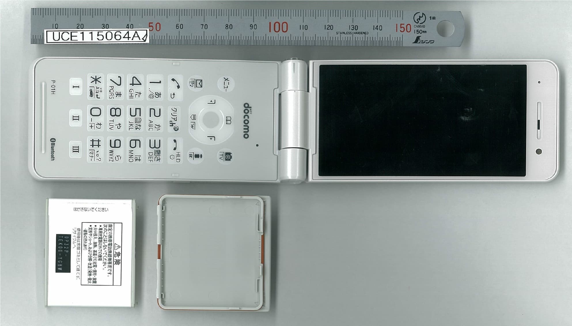
UCE115064A
Sep 29, 2015Single Mode UMTS Mobile Phone with Bluetooth and RFID
Equipment Class
DSS - Part 15 Spread Spectrum Transmitter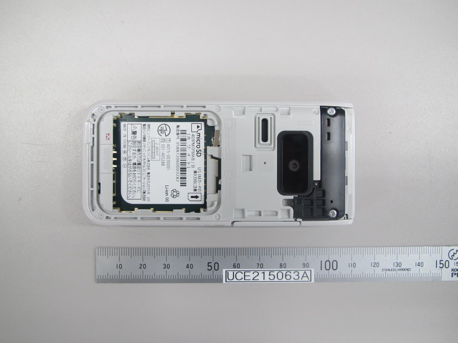
UCE215063A
Apr 09, 2015Dual Mode GSM/ UMTS Mobile Phone with Bluetooth
Equipment Class
DSS - Part 15 Spread Spectrum Transmitter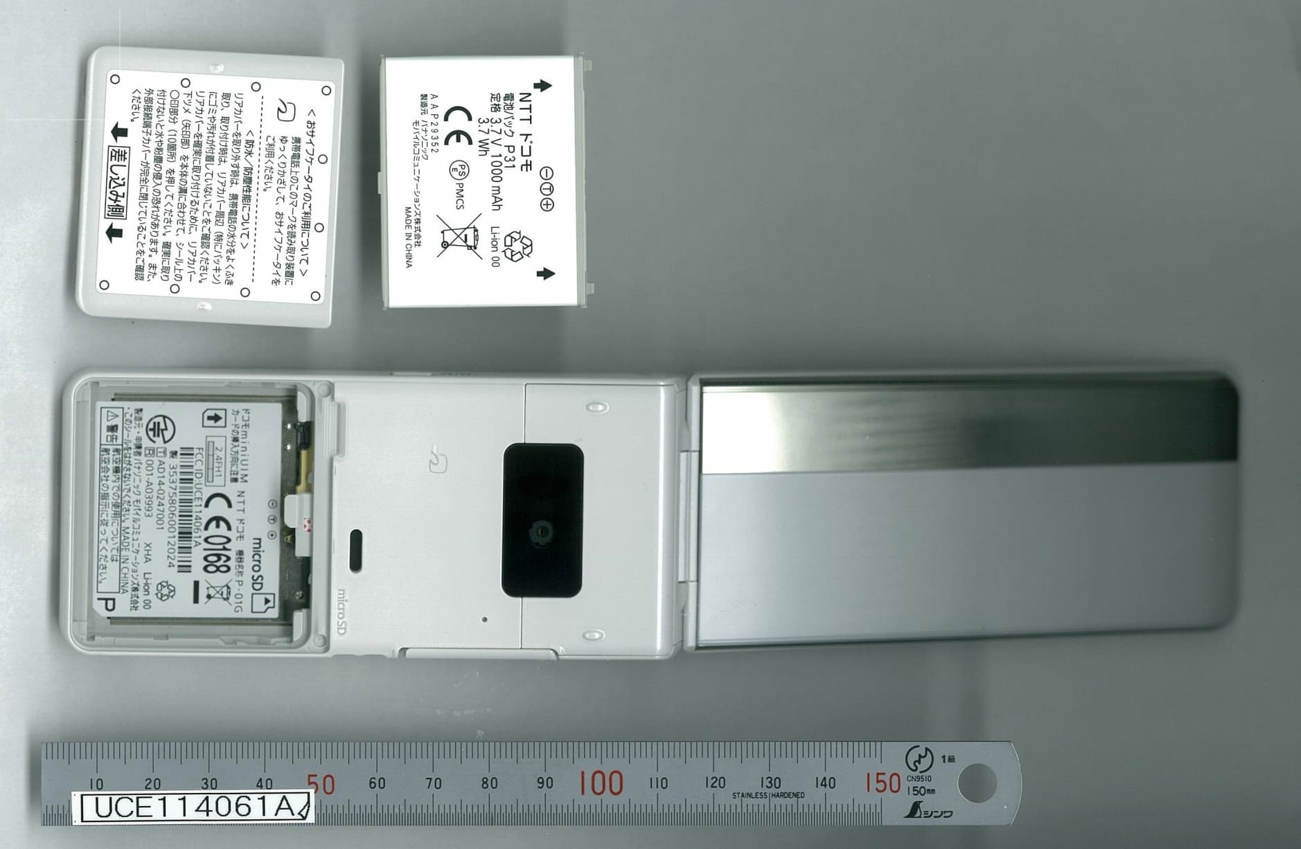
UCE114061A
Sep 11, 2014Single Mode UMTS Mobile Phone with Bluetooth and RFID
Equipment Class
DSS - Part 15 Spread Spectrum Transmitter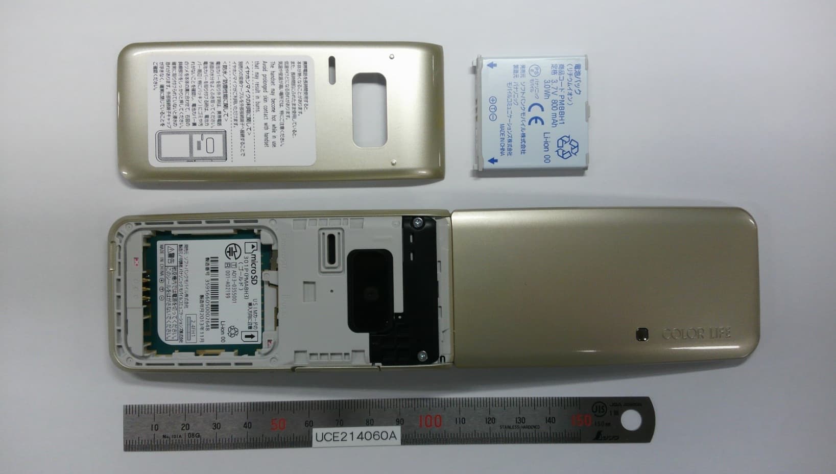
UCE214060A
Dec 17, 2013Dual Mode GSM/UMTS Mobile Phone with Bluetooth
Equipment Class
PCE - PCS Licensed Transmitter held to ear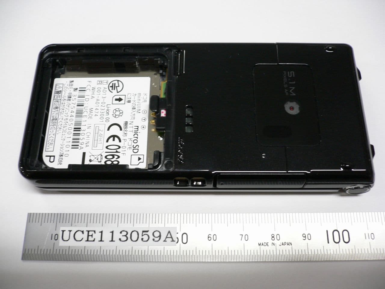
UCE113059A
Sep 09, 2013Single Mode UMTS Phone with Bluetooth
Equipment Class
DSS - Part 15 Spread Spectrum Transmitter