UDDQDPSQuail Digital DECT Communication system
Quail Ltd.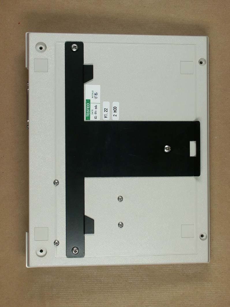
Click to zoom
Application Details
- Equipment Class
- PUB - Part 15 Unlicensed PCS Base Station
- Date of Grant
- Sep 17, 2006
- Application Purpose
- Original Equipment
- Date of Application
- Sep 17, 2006
- Equipment Note
- Quail Digital DECT Communication system
- Frequency Range
- 1921.54000000 - 1928.45000000
- Company
- Quail Ltd.
- Country
- United Kingdom
Documents & Files
Document Text
Text extracted from the exhibit documents filed with the FCC. Open a document above to read the original.
Users Manual
QUAIL DIGITAL USER MANUAL WWW.QUAILDIGITAL.COM QD Belt Pack System User Manual Contents Safety Precautions and Important Notices 2 Introduction 3 Preparations for Use 3 Installing the Primary Station and Registration Point 4 Installing the Charger Unit 5 Registering the Belt Packs 6 Using the Belt Pack 6 Belt Pack LED status table 8 Using the Headset 9 Replacing a Belt Pack Battery 10 Frequently Asked Questions 11 Care and Maintenance 12 Servicing 12 Warranty Statement 12 Technical Specifications 13 March 2006 1 QUAIL DIGITAL USER MANUAL WWW.QUAILDIGITAL.COM SAFETY PRECAUTIONS AND IMPORTANT NOTICES When using your Quail system, these basic safety precautions should always be followed to reduce risk of fire, electric shock and injury 1) Never push objects of any kind into your Quail equipment through the cabinet openings. They may touch dangerous voltage points resulting in risk of fire or shock. 2) To reduce the risk of electric shock do not disassemble any of the Quail equipment. Take it to a qualified service technician when repair work is required. Opening or removing covers may expose you to dangerous voltage or other risks. Incorrect re-assembly could cause electric sock when the unit is subsequently used. 3) Unplug the Primary Station or Charger Unit from the wall outlet and refer servicing to qualified personnel under the following conditions: • When the power supply cord, plug or adaptor is damaged or frayed • If liquid has been spilled into the product • If the product has been exposed to rain or water • If the product does not operate properly after instructions have been followed • If the product has been dropped, or the cabinet appears damaged • If the product exhibits a distinct change in performance 4) Avoid using the equipment during a lightening storm, there may be a remote risk of electric shock from lightening. If possible, unplug the AC power for the duration of the lightening storm. 5) Never dispose of batteries in a fire. There is a serious risk of explosion and / or the release of highly toxic chemicals. Dispose of used batteries in accordance with local regulations. 6) When not using your Quail system for an extended period of time, please disconnect the mains power from the Primary Station and Charger Unit, and remove the batteries from the belt packs. 7) The Quail belt pack uses a specific Quail rechargeable NiMh battery. Do not substitute any other battery. 2 QUAIL DIGITAL USER MANUAL WWW.QUAILDIGITAL.COM INTRODUCTION Thank you for choosing a Quail Digital wireless communication system. You have selected the latest in Digital technology to improve your communications, but in order to make the best use of your equipment you need to read the following instructions carefully. If you have any further questions about the use of your equipment, please contact your local distributor through our website www.quaildigital.com PREPARATIONS FOR USE To use the system you will require the following: 1 QD-PS Digital Primary Station 2+ QD-BP Digital belt packs 1+ QD-CG7 four port charger units 1 QD-RH5 headset per belt pack 1 Registration Point & Cable 2 Power Cables For the belt packs to operate their batteries will need to be charged. When your system arrives, plug the charger unit into the mains power socket. The power indicator will illuminate green. Now place the belt packs in the charger ports. The LED on each belt pack will initially flash red to show that it has located itself correctly, and is now charging. When fully charged, the LED will flash green, and the belt pack is ready for use. This takes about 6 hours, and the belt pack will then provide about 30 hours of use before it needs to be charged again. Note: To get the best performance out of your rechargeable batteries, you should first fully charge the belt packs. The initial charge may take up to 16 hours. NOTE: The Quail Digital Primary Station is supplied with two DECT modules to allow a maximum of 6 users. 3 QUAIL DIGITAL USER MANUAL WWW.QUAILDIGITAL.COM $INSTALLING THE PRIMARY STATION AND REGISTRATION POINT Installing the Primary Station The Primary Station defines the working area of the system, and needs to be located centrally within the desired coverage zone. In an open space you will be able to use the belt packs up to 150m from the Primary Station, but once inside a building this range will be reduced by the building’s structure and internal fittings. e.g. large metal objects like cold stores are potentially a problem as they block the radio frequency path. This reduction in range is difficult to assess accurately unless a site survey is carried out, but typically in most buildings you can expect to operate at least 50m from the Primary Station. This is a radius measurement, so teams of belt packs users can easily communicate over a 100m distance. If you would like to invest in a site survey, please contact your local distributor. The Primary Station should be wall- mounted at least 2 metres from the ground for best performance. In general use there is no need for users to touch the Primary Station, and installing it out of reach is OK. In many commercial premises with suspended ceilings, this will mean mounting just below ceiling level. Do not site the Primary Station above a metal frame suspended ceiling. The Primary Station must always be mounted in a “landscape” orientation, as shown above. 4 QUAIL DIGITAL USER MANUAL WWW.QUAILDIGITAL.COM 1 2 3 4 The unit should be secured to the wall using the supplied mounting bracket as shown in fig 1 and 2. Lower the Primary Station onto the wall section of the bracket (fig 3), and make sure is clipped correctly. You can use a screwdriver to clip the brackets together as shown in Fig. 4. Once positioned, plug the Primary Station into the mains power socket using the supplied cable. The power indicator will illuminate green. Installing the Registration Point The cable for the Registration Point should be inserted into the socket at the top of the Primary Station…
Text truncated - open the document above for the full version.
External Photos
ELECTRONIC TECHNOLOGY SYSTEMS DR.GENZ GMBH ETS Dr. Genz GmbH, Germany Registration number: G0M20602-0210-C-1 Page 1 of 11 Appendix A. Pictures ELECTRONIC TECHNOLOGY SYSTEMS DR.GENZ GMBH ETS Dr. Genz GmbH, Germany Registration number: G0M20602-0210-C-1 Page 2 of 11 ELECTRONIC TECHNOLOGY SYSTEMS DR.GENZ GMBH ETS Dr. Genz GmbH, Germany Registration number: G0M20602-0210-C-1 Page 3 of 11
ID Label/Location Info
4. Quail Digital FCC ID Label location Information The following pages desribe where the FCC ID labels are located on the Quail Digital Primary Station and on the Quail Digital Belt pack. 4.1 Primary Station FCC ID Label location. On the Primary Station the FCC ID label is located at the rear metal panel, together with the product part number and the serial number. See pictures below: Quail Digital 92 Lots Road, SW10 0QD, London, United Kingdom. www.quaildigital.com 4.2 Primary Station FCC statement Label location. On the Primary Station the FCC statement label is located at the rear of the unit. See pictures below: Quail Digital 92 Lots Road, SW10 0QD, London, United Kingdom. www.quaildigital.com Quail Digital 92 Lots Road, SW10 0QD, London, United Kingdom. www.quaildigital.com
Internal Photos
ELECTRONIC TECHNOLOGY SYSTEMS DR.GENZ GMBH ETS Dr. Genz GmbH, Germany Registration number: G0M20602-0210-C-1 Page 4 of 11 ELECTRONIC TECHNOLOGY SYSTEMS DR.GENZ GMBH ETS Dr. Genz GmbH, Germany Registration number: G0M20602-0210-C-1 Page 5 of 11 ELECTRONIC TECHNOLOGY SYSTEMS DR.GENZ GMBH ETS Dr. Genz GmbH, Germany Registration number: G0M20602-0210-C-1 Page 6 of 11 ELECTRONIC TECHNOLOGY SYSTEMS DR.GENZ GMBH ETS Dr. Genz GmbH, Germany Registration number: G0M20602-0210-C-1 Page 7 of 11 ELECTRONIC TECHNOLOGY SYSTEMS DR.GENZ GMBH ETS Dr. Genz GmbH, Germany Registration number: G0M20602-0210-C-1 Page 8 of 11
RF Exposure Info
ETS Dr. Genz GmbH, Germany Registration number: «Registriernummer»-C-1.DOC Page 33 of 56 ELECTRONIC TECHNOLOGY SYSTEMS DR.GENZ GMBH 3.1.11 Radio frequency radiation exposure, FCC 15.319 (i); RSS-102 UPCS devices are subject to the radio frequency radiation exposure requirements specified in FCC parts 1.1307 (b), 2.1091, 2.1093 and RSS-102, as appropriate. All equipment shall be considered to operate in a “general population / uncontrolled environment. For portable devices tests according to IEEE 1528 are requested, if applicable. Consideration of radio frequency radiation exposure for EUT is done as SAR test acc. IEEE 1528 MPE calculation as below SAR test results: not applicable MPE calculation: Please find radiated power test results in Appendix J. The EUT is considered as a mobile device according to OET Bulletin 65, Edition – 97 – 01. Therefore distance to human body of min. 20 cm is determined. The internal / external antennas used for this mobile transmitter must provide a separation distance of at least 20 cm from all persons and must not be co-located or operating in conjunction with any other antenna or transmitter. A safety statement concerning minimum separation distances from enclosure of the device will be integrated in the user’s manual to provide end-users with transmitter operating conditions for satisfying RFE exposure compliance. Formula: S = EIRP / 4πR 2 Calculation: EIRP Radiated Power [dBm] 12.46 EIRP Radiated Power [mW] 17.62 mW R Distance [cm] 20 S Power Density [mW/cm 2 ] 0.0035 Limit: The limit of Power density for General Population / Uncontrolled Exposure is 1.0 mW/cm 2 . Compliance with the requirements will be considered by calculation of power density derived from radiated power value. Verdict: Pass Fail For radiated power test results see Appendix I.
Test Report
ELECTRONIC TECHNOLOGY SYSTEMS DR. GENZ GMBH TEST - REPORT FCC PART 15 D for Isochronous UPCS devices RSS-213 for LE-PCS devices FCC ID: UDDQDPS IC ID: 6402A-QDPS Test report no.: G0M20602-0210-C-1 Certificate 1983-01 ELECTRONIC TECHNOLOGY SYSTEMS STORKOWER STRASSE 38C, D-15526 REICHENWALDE B. BERLIN DR. GENZ GMBH PHONE +49-33631-888 00 FAX +49-33631-888 66 ETS Dr. Genz GmbH, Germany Registration number: G0M20602-0210-C-1 Page 2 of 56 ELECTRONIC TECHNOLOGY SYSTEMS DR.GENZ GMBH TABLE OF CONTENTS 1 General information 1.1 Notes 1.2 Testing laboratory 1.3 Details of approval holder 1.4 Application details 1.5 Test item 1.6 Test standards 2 TECHNICAL TEST 2.1 Summary of test results 2.2 Test environment 2.3 Test equipment utilized 2.4 Examinations and Test Procedures 3 RESULTS OF EXAMINATIONS AND TESTS 3.1. Examinations and Test Procedures 3.1.1 Coordination with fixed microwave service, FCC 15.307 (b) 3.1.2 Reference to Subpart B, FCC 15.309 (b) 3.1.3 Conducted limits AC Power line, FCC 15.315, 15.207; RSS-213 4.2; 6.3 3.1.4 Antenna requirement, FCC 15.317, 15.203 3.1.5 Modulation techniques, FCC 15.319 (b); RSS-213 6.1 3.1.6 Emission bandwidth, FCC 15.323 (a); FCC 15.31 (e); RSS-213 6.4 3.1.7 Peak Transmit Power, FCC 15.319 (c); RSS-213 4.3.1, 6:5 3.1.8 Power spectral density, FCC 15.319 (d); RSS-213 4.3.1, 6:6 3.1.9 Directional gain of the antenna, FCC 15.319 (e); RSS-213 4.1 (e) 3.1.10 Automatic discontinuation of transmission, FCC 15.319 (f); RSS-213 4.3.4 (a) ETS Dr. Genz GmbH, Germany Registration number: G0M20602-0210-C-1 Page 3 of 56 ELECTRONIC TECHNOLOGY SYSTEMS DR.GENZ GMBH 3.1.11 Radio frequency radiation exposure, FCC 15.319 (i); RSS-Gen 5.5 3.1.12 Monitoring threshold; Least interfered channel; FCC 15.323 (c)(2); (c)(5) (c)(9); RSS-213 4.3.4 (b)(2) 3.1.13 Monitoring of intended transmit window and maximum reaction time, FCC 15.323 (c)(1); RSS-213 4.3.4 (b)(1) 3.1.14 Monitoring bandwidth, FCC 15.323 (c)(7); RSS-213 4.3.4 (b)(7) 3.1.15 Random waiting interval, FCC 15.323 (c)(6); RSS-213 4.3.4 (b)(6) 3.1.16 Duration of transmission, FCC 15.323 (c)(3); RSS-213 4.3.4 (b)(3) 3.1.17 Connection acknowledgement, Unacknowledged transmissions, FCC 15.323 (c)(4); RSS-213 4.3.4 (b)(5) 3.1.18 Selected channel confirmation, Segment occupancy; FCC 15.323 (c)(5) 3.1.19 Monitoring antenna, FCC 15.323 (c)(8); RSS-213 4.3.4 (b)(8) 3.1.20 Duplex connections, FCC 15.323 (c)(10); RSS-213 4.3.4 (b)(10) 3.1.21 Alternative monitoring interval for co-located devices, FCC 15.323 (c)(11); RSS-213 4.3.4 (b)(11) 3.1.22 Fair access to spectrum related to (c)(10) and (c)(11), FCC 15.323 (c)(12); RSS-213 4.3.4 (b)(12) 3.1.23 Emissions inside and outside the sub-band, FCC 15.323 (d); RSS-213 6.7 3.1.24 Frame period, FCC 323 (e); RSS-213 4.3.(c). 3.1.25 Frequency stability, FCC 323 (f); RSS-213 6.8 3.1.26 Receiver spurious emissions; RSS-213 6.8 ETS Dr. Genz GmbH, Germany Registration number: G0M20602-0210-C-1 Page 4 of 56 ELECTRONIC TECHNOLOGY SYSTEMS DR.GENZ GMBH 1 General Information 1.1 Notes The purpose of conformity testing is to increase the probability of adherence to the essential requirements or conformity specifications, as appropriate. The complexity of the technical specifications, however, means that full and thorough testing is impractical for both technical and economic reasons. Furthermore, there is no guarantee that a test sample which has Passed all the relevant tests conforms to a specification. Neither is there any guarantee that such a test sample will interoperate with other genuinely open systems. The existence of the tests nevertheless provides the confidence that the test sample possesses the qualities as maintained and that is performance generally conforms to representative cases of communications equipment. The test results of this test report relate exclusively to the item tested as specified in 1.5. The test report may only be reproduced or published in full. Reproduction or publication of extracts from the report requires the prior written approval of the ELECTRONIC TECHNOLOGY SYSTEMS DR. GENZ GMBH. Specific Conditions: Usage of the hereunder tested device in combination with other integrated or external antennas requires at least additional output power measurements, spurious emission measurements, conducted emission measurements (AC supply lines) and radio frequency exposure evaluations for each individual configuration are performed, for certification by competent authorities FCC; IC. This report is related to FCC Part 15 D applied to UPCS devices of which technology is derived from DECT standard. Additional this report covers the requirement of RSS-213, 2 GHz Licence exempt Personal Communications Services Devices (LE-PCS) released by Industry Canada (IC). In following the term UPCS covers the term LE-PCS too. Tester: 02.08.2006 W. Treffke Date ETS-Lab. Name Signature Technical responsibility for area of testing: 02.08.2006 N. Kaspar Date ETS Name Signature ETS Dr. Genz GmbH, Germany Registration number: G0M20602-0210-C-1 Page 5 of 56 ELECTRONIC TECHNOLOGY SYSTEMS DR.GENZ GMBH 1.2 Testing laboratory 1.2.1 Location ELECTRONIC TECHNOLOGY SYSTEM DR. GENZ GMBH (ETS) Storkower Straße 38c D-15526 Reichenwalde b. Berlin Germany Telefon : +49 33631 888 00 Telefax : +49 33631 888 66 1.2.2 Details of accreditation status A CCREDITED TESTING LABORATORY DAR-REGISTRATION NUMBER: DAT-P-201/96 ACCREDITED COMPETENT BODY DAR- REGISTRATION NUMBER: BPT-ZE-026/96 FCC FILED TEST LABORATORY REG. NO. 96970 Bluetooth Qualification Test Facility (BQTF) Accredited by Bluetooth Qualification Review Board (BQRF) I NDUSTRY CANADA FILED TEST LABORATORY REG. NO. IC 3470 A2LA ACCREDITED Certificate Number: 1983-01 1.2.3 Test location if different from 1.2.1 ETS PRODUCT SERVICE AG Storkower Straße 38c D-15526 Reichenwalde b. Berlin Germany Telefon : +49 33631 888 00 Telefax : +49 33631 888 660 ETS Dr. Genz GmbH, Germany Registration number: G0M20602-0210-C-1 Page 6 of 56 ELECTRONIC TECHNOLOGY SYSTEMS DR.GENZ GM…
Text truncated - open the document above for the full version.
Test Setup Photos
ELECTRONIC TECHNOLOGY SYSTEMS DR.GENZ GMBH ETS Dr. Genz GmbH, Germany Registration number: G0M20602-0210-C-1 Page 9 of 11 ELECTRONIC TECHNOLOGY SYSTEMS DR.GENZ GMBH ETS Dr. Genz GmbH, Germany Registration number: G0M20602-0210-C-1 Page 10 of 11 ELECTRONIC TECHNOLOGY SYSTEMS DR.GENZ GMBH ETS Dr. Genz GmbH, Germany Registration number: G0M20602-0210-C-1 Page 11 of 11
Contact Information
Applicant
Jose Barrera Guerrero(Technical Manager)
Test Firm
Eurofins Product Service GmbHRobert Kschiwan-Kaspar
Technical Specifications
| # | Rule Parts | Frequency Range | Power Output |
|---|---|---|---|
| 1 | 15D | 1.92 GHz - 1.93 GHz | 119.00 mW |
Other Applications from Quail Ltd.
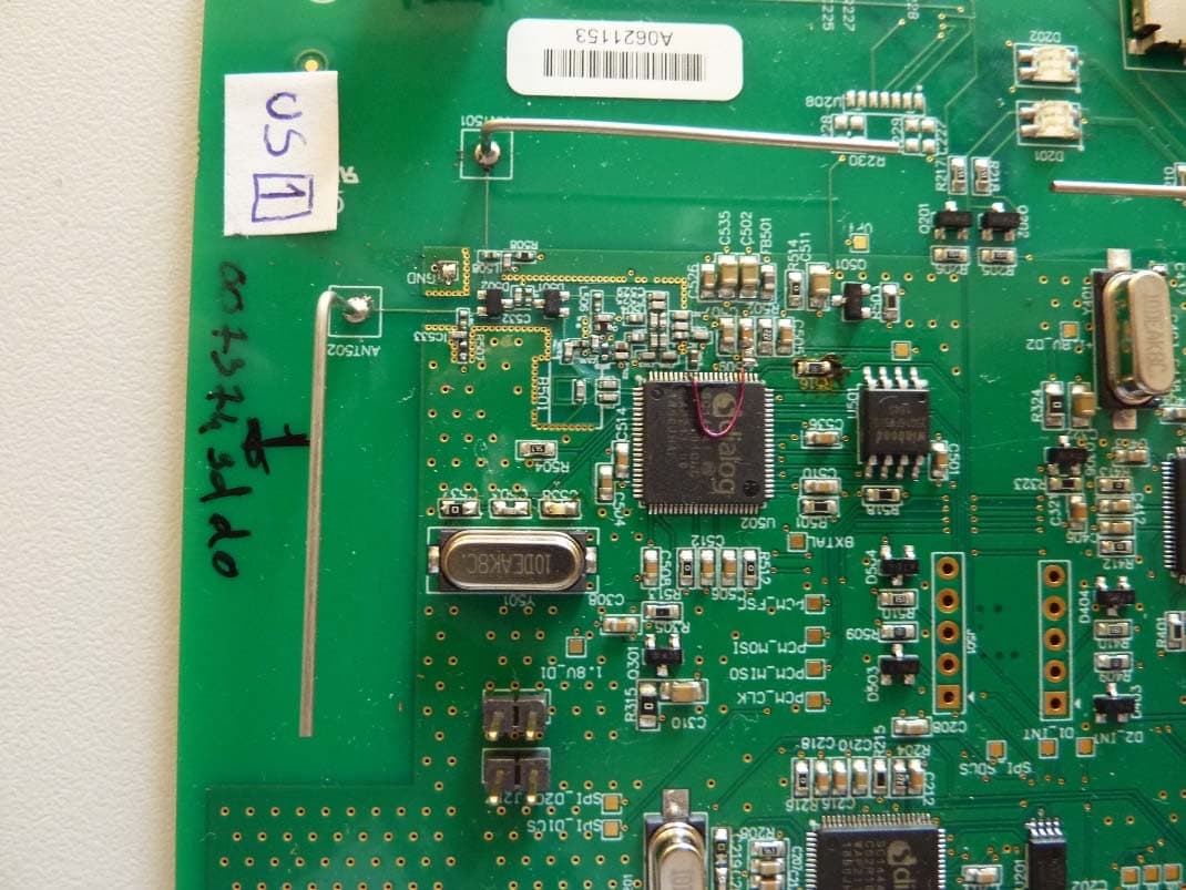
UDDQP11BS
Jul 04, 2021DECT Base station
Equipment Class
PUB - Part 15 Unlicensed PCS Base Station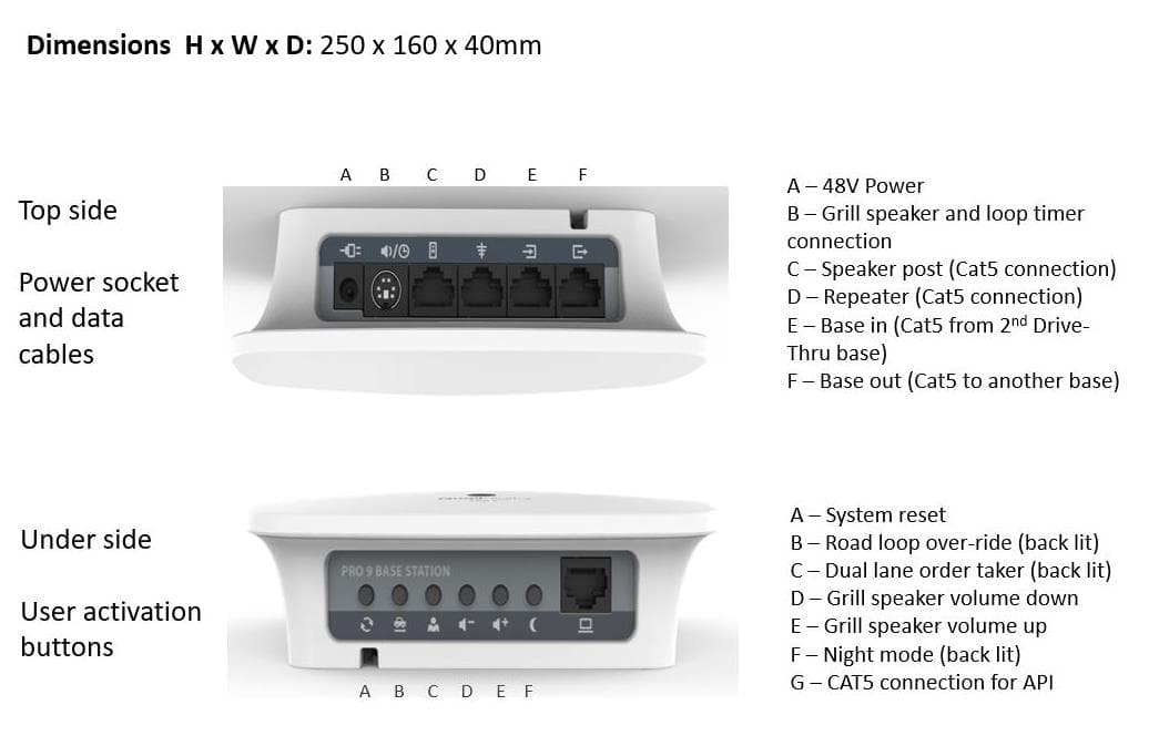
UDDQP9BS
Jan 05, 2021Quail Pro 9 Base Station
Equipment Class
PUB - Part 15 Unlicensed PCS Base Station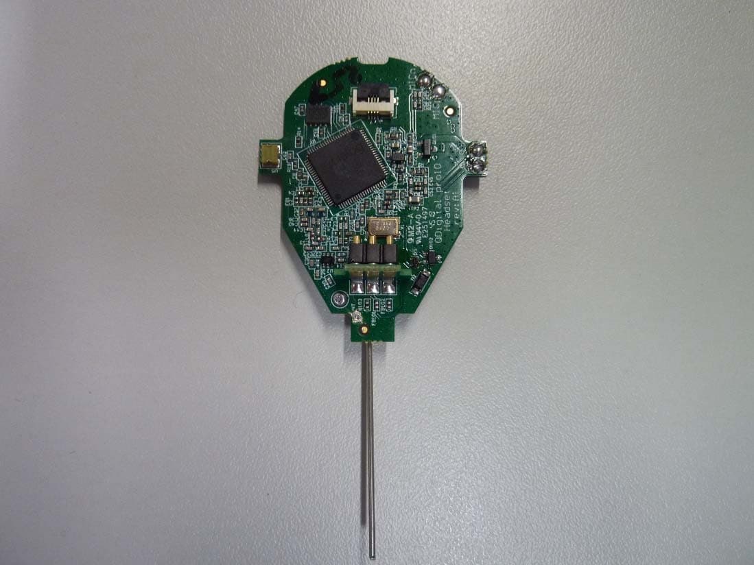
UDDQP10HS
Nov 24, 2020DECT headset
Equipment Class
PUE - Part 15 Unlicensed PCS portable Tx held to ear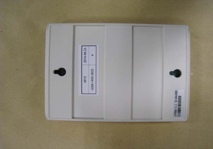
UDDQP7BS
Jul 14, 2014Dect Wireless Communication
Equipment Class
PUB - Part 15 Unlicensed PCS Base Station
UDDQDTB
Jan 29, 2013Q-DTB (QD Drive Thru Base)
Equipment Class
PUB - Part 15 Unlicensed PCS Base Station