UDDQP10HSDECT headset
Quail Ltd.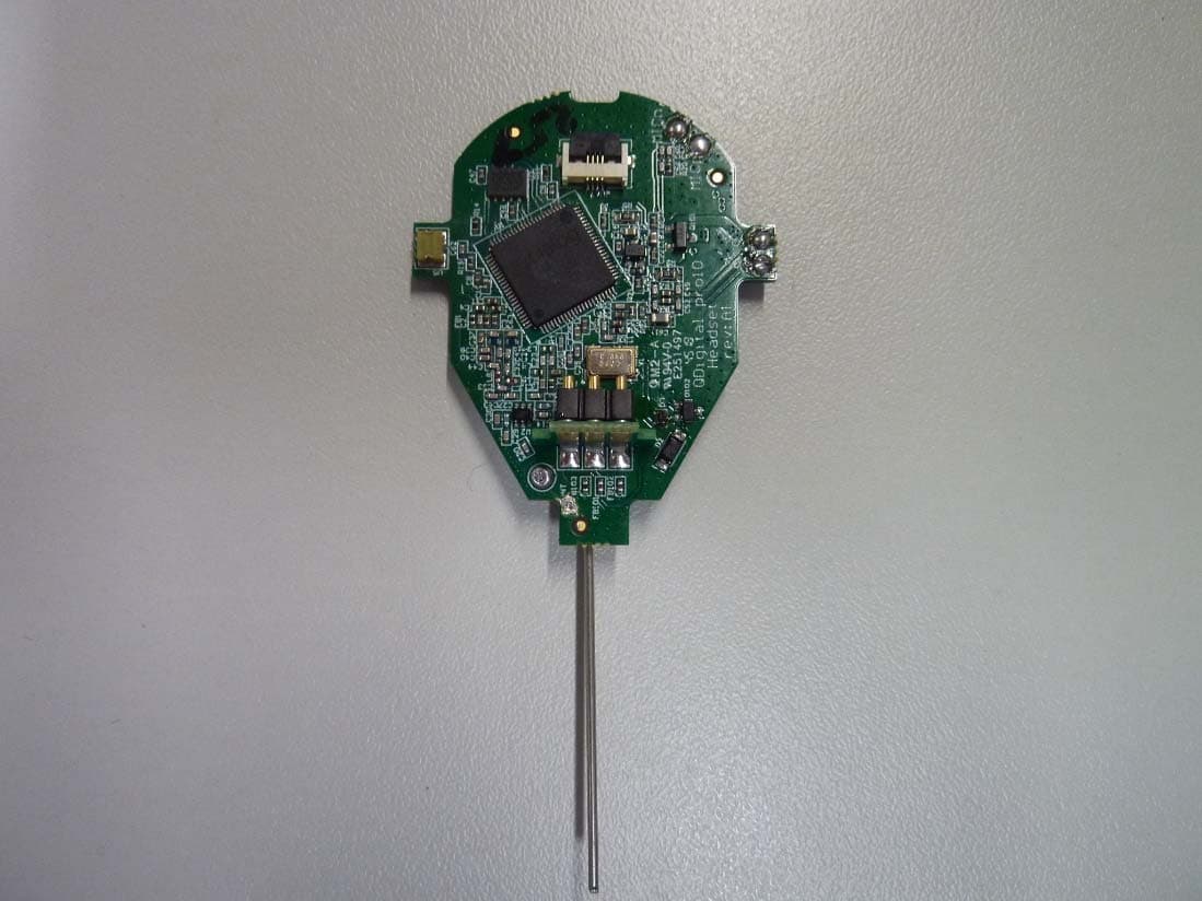
Click to zoom
Application Details
- Equipment Class
- PUE - Part 15 Unlicensed PCS portable Tx held to ear
- Date of Grant
- Nov 24, 2020
- Application Purpose
- Original Equipment
- Date of Application
- Nov 24, 2020
- Equipment Note
- DECT headset
- Frequency Range
- 1921.53600000 - 1928.44800000
- Company
- Quail Ltd.
- Country
- United Kingdom
Documents & Files
Document Text
Text extracted from the exhibit documents filed with the FCC. Open a document above to read the original.
Users Manual
Pro10 Headset System Installation Manual page 2 This guide specifies how the Pro10 headset system should be installed and commissioned. The LEDs on the base, registration point and headset use a sequence of colours and pulses to indicate the status of the system and the item, which are explained in this guide. Contents Pre-Installation Procedure Tools required to install Pro10 system page 3 Pro10 system components Step 1 - Charging headsets Step 2 - Pre-installation survey Step 3 - Locating base stations Step 4 - Conducting your range test page 5 Step 5 - Positioning the registration point Installation Procedure Step 6 - Installing base stations and registration point page 6 Step 7 – Connecting base stations and registration point page 7 Step 8 - Synchronising base stations Step 9 - Setting up the charger page 8 Step 10 - Registering headsets Step 11 - Testing the installation page 9 Appendix A - Headset battery fitting page 10 Appendix B - Headset functionality & system troubleshooting page 11 Appendix C - Pro10 products and codes page 12 Regulatory Notices page 13 page 3 Pre-Installation Procedure Tools required to install Pro10 system: • Phillips screwdriver • Category 5/6/7 network cable • drill with 1/8” masonry bit • RJ45 crimp tool • pencil • cable stripper • tape measure • network cable tester • 1m patch cable Pro10 system components: Q-P10HS - headset(s) including battery and headband or neckband Q-P10BS - base station(s) with 48v power supply Q-P10CH - 6 port headset charger with 5v power supply Q-P10RP - registration point Q-P10SHELF - shelf for headset charger (optional) Step 1 - Charging headsets Unpack the Q-P10CH charger(s) and Q-P10HS headsets. Power-up the charger(s) using the 5v power supply supplied in the box. The green power light will illuminate. Place the batteries into the headsets (see Appendix A) and place the headsets into the charger ports. The headset LED is blue and will quick-pulse every second if unregistered and pulse every 4 seconds if registered when not charging. They pulse blue once every 10s when charging and then turn solid blue when fully charged. Charging from flat can take up to 4 hours. Step 2 - Pre-installation survey The system will work to specification if the headsets have uninterrupted range coverage in all operational areas asked for by the client, which may require the installation of more than one base station. It’s normal practice to exclude plant rooms, lift shafts, cold stores and stair wells from the coverage required. Before installing the equipment, you should confirm the areas that require coverage (inside and outside) with the customer. Note that the battery chargers must be located well within the coverage area, never out of range nor at the edge of range of a base station. Step 3 - Locating base stations Review Network coverage A and B on page 4, as examples of suggested base station positions in two typical premises layouts. In Network coverage A, the size of the premise is relatively small and can be covered fully using a single base station, located just outside the main floor area to reduce visual impact. In the Network coverage B example, the premises are much larger and three base stations are required to give full coverage in all areas of the ancillary and main floor spaces. Always apply these rules when deciding on locating the base station(s): • Never place bases in cupboards, behind pipework, above ceilings, above or in cable trays, above lighting networks, around air-conditioning ducts, around electricity control boards and structural metalwork. All of these will significantly reduce range. page 4 • Always locate your base stations so that they have, as much as possible, clear line of sight in the area you want to cover. Any solid wall, doorway, fridge, plant room area or mezzanine floor in immediate proximity in front of the base station will reduce range. • The base station must be positioned upright on the wall and secured with both attaching screws. • The base should be located a minimum 3m (9ft) from floor level unless the ceiling is lower, in which case as high as you can. In Network coverage A, a single base is sufficient. The shading shows how the range of a single base covers the whole premises in this instance. In Network coverage B, three bases are required to cover the three separate distinct areas. When planning the positioning of the bases there should be a 5m (15ft) overlap in the signal from two interconnecting bases to allow the headsets to switch between bases seamlessly. If the call drops when moving from one base to another, move them closer together by at least 5m. Slave base station 2 Network coverage A - Small store layoutNetwork coverage B - Large store layout Stock room Staff room Cash desks Base station Charger & headsets Stock room/loading bay Firewalls Primary base station Staff room Plant room & prep area Secondary base station Network cable Charger & headsets Base station network coverage Secondary base station page 5 figure 1 - Registration point connections Step 4 - Conducting your range test To conduct your range test, you should temporarily locate your first base station in the optimal position you think is correct for delivering maximum range. Then, temporarily connect the registration point to the base station with a Cat 5 patch cable from the base to the registration point. Power up the base station using the 48v power supply and an extension cable. Leave it for 2 minutes to boot-up (LEDs on the front of the base station will start amber and then revert to standby mode of red and green). The registration point will start to flash amber and then revert to pulsing green every 10 seconds. Take a headset and hold the talk button side to the registration point (within 15cm) to register it. The registration point LED will fast blink green and then give a solid green LED for 3 seconds to indicate registration complete. Then hold the headset to your ear. You will hear a single tone in you…
Text truncated - open the document above for the full version.
Users Manual
Pro11 Headset System Installation Manual Pro11 Headset Q-P11HS Pro11 Base Station Q-P11BS Pro11 Charger Q-P11CH STEP 1 • The base station can be located in either the OR or the monitoring room. • Identify a location with clear space around it and nothing in front (the base is a transmitter). (figure 1) • You need a power socket close by. Connect the Q-PSU48 power supply into the wall socket and then into the socket in the top of the base. • The base should be fitted to the wall using the two velcro strips supplied, peeling back the protective covers. Do not fit the base to the wall upside down or sideways. • When the power is connected, the LED on the front will start AMBER during booting up, then go GREEN after 30 secs. STEP 2 • Set up the 6-port battery charger. Select a clear desk or cabinet top in the monitoring room close to a power socket that DOESN’T get switched off or unplugged at night. (figure 2) • Connect the Q-PSU5 power supply into the back of the charger and weave the cable around the gates. (figure 3) • Switch on the power. The LED on the front of the charger will illuminate GREEN. figure 2 figure 3 figure 1 STEP 3 • Place a battery into each headset, by removing the outer sleeve on the body of the headset using your fingernail. (figure 4) • Remove the tape over the battery contacts, then slot the battery into the chamber. It only goes in one way, so turn it over if it won’t slide in. Clip the sleeve back on. As soon as the battery is connected the LED will flash BLUE every second. • Place all headsets into the charger. The headsets are now charging. The LED on the headset will flash BLUE every 10 seconds. STEP 4 • To register a headset to the base station, take one headset at a time out of the charger and hold the outside face of the headset to the bottom of the base. (figure 5) • As soon as you do this, the LED on the base will flash AMBER, and then go solid AMBER, which means the headset is registered. Place the headset back in the charger and repeat the process with the next one. • Leave all headsets in the charger for 2 minutes to synchronise with each other. • To test, put on a headset, press the talk button and speak into the headset - if you can hear your own voice, the headset is working and ready for use. (figure 6) • To use a headset in ‘hands-free’ mode, press the talk button for a second; the blue LED will remain on, indicating that you are hands-free. To use in normal ‘Push-To- Talk’ mode, remove your finger from the talk button when you finish speaking. To change volume, press the volume button; it has 5 levels. figure 4 figure 5 figure 6 Customer support • www.quaildigital.com/video/QD-Pro11-installation.mp4 Headset audioStatusNext steps Bloop-bleepCall dropEither you’ve moved out of range of base (move towards it), or base has no power (check LED on front of base). If LED out, call Tech support. 2 beeps every 10 secondsOut of rangeHeadset is not in range of base (move towards it), or base has no power (check LED on front of base). If LED out, call Tech support. 3 beeps every 60 secondsBattery lowPut headset in charger and take another headset. 1 beep every 3 seconds (and fast flashing LED) Registration requiredHeadset is working but needs to be registered to the system. Fault/symptomsAction Headset has been in charger, but LED isn’t flashing Determine whether it’s a headset or battery fault. Swap the battery from one in a working headset. If changing the battery clears the fault, then throw away the faulty battery and order a new one. If not, send the headset back for repair/replacement. Headset LED is pulsing as normal every 4 seconds but audio not working’ Put the headset back into the charger for at least 10 seconds. This should reset the headset. If it doesn’t, remove the battery from the headset then replace it again. If this doesn’t clear the fault, send the headset back for repair/ replacement. Headset functionality and system troubleshooting Useful information • If you have multiple ORs and multiple Pro11 systems you can move headsets from one room to another by following Step 4 overleaf. When a headset is registered to another base station it automatically deregisters from the previous one. • If you hear 2 beeps in your ear, it means you’ve gone out of range. Move back towards the base station it’s registered to and the headset will reconnect. • Batteries will last for 16 hours on standby and up to 10 hours in hands-free mode. Always put headsets back into the charger when not in use. • Wipe down headsets and charger with hygiene wipes routinely. • Call your service provider if you have any problems. Regulatory Notices Headset - HVIN: Q-P11HS FCC ID: UDDQP10HS This device complies with Part 15 of the FCC Rules. Operation is subject to the following two conditions: (1) This device may not cause harmful interference, and (2) this device must accept any interference received, including interference that may cause undesired operation. Changes or modifications not expressly approved by the party responsible for compliance could void the user’s authority to operate the equipment. This equipment complies with FCC radiation exposure limits set forth for an uncontrolled environment. Note: This equipment has been tested and found to comply with the limits for a Class B digital device, pursuant to part 15 of the FCC Rules. These limits are designed to provide reasonable protection against harmful interference in a residential installation. This equipment generates, uses and can radiate radio frequency energy and, if not installed and used in accordance with the instructions, may cause harmful interference to radio communications. However, there is no guarantee that interference will not occur in a particular installation. If this equipment does cause harmful interference to radio or television reception, which can be determined by turning the equipment off and on, the user is encouraged to try to correct the interference by one or more of the following meas…
Text truncated - open the document above for the full version.
External Photos
2019-06-27 Page 1 of 7 Annex A: Photographs of the Test Set-up Photo 1: Radiated Emission Photo 2: Radiated Emission Test report no.: 1-7183/18-01-14 2019-06-27 Page 2 of 7 Photo 3: Conducted Emission Test report no.: 1-7183/18-01-14 2019-06-27 Page 3 of 7 Annex B: External Photographs of the EUT Photo 1: Photo 2: Test report no.: 1-7183/18-01-14 2019-06-27 Page 4 of 7 Photo 3: Photo 4: Test report no.: 1-7183/18-01-14 2019-06-27 Page 5 of 7 Photo 5: Test report no.: 1-7183/18-01-14 2019-06-27 Page 6 of 7 Annex C: Internal Photographs of the EUT Photo 1: Photo 2: Test report no.: 1-7183/18-01-14 2019-06-27 Page 7 of 7 Photo 3:
ID Label/Location Info
FCC Marking IC Marking Printed Q-P10HS marking (HVIN) Printed Q-P11HS marking (HVIN)
Internal Photos
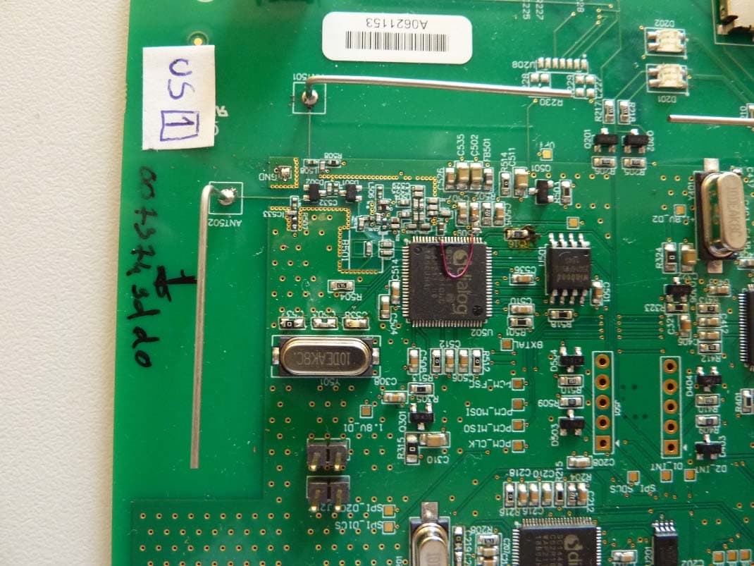
2019-06-27 Page 1 of 7 Annex A: Photographs of the Test Set-up Photo 1: Radiated Emission Photo 2: Radiated Emission Test report no.: 1-7183/18-01-14 2019-06-27 Page 2 of 7 Photo 3: Conducted Emission Test report no.: 1-7183/18-01-14 2019-06-27 Page 3 of 7 Annex B: External Photographs of the EUT Photo 1: Photo 2: Test report no.: 1-7183/18-01-14 2019-06-27 Page 4 of 7 Photo 3: Photo 4: Test report no.: 1-7183/18-01-14 2019-06-27 Page 5 of 7 Photo 5: Test report no.: 1-7183/18-01-14 2019-06-27 Page 6 of 7 Annex C: Internal Photographs of the EUT Photo 1: Photo 2: Test report no.: 1-7183/18-01-14 2019-06-27 Page 7 of 7 Photo 3:
RF Exposure Info
© CTC advanced GmbH Page 1 of 28 BNetzA - CAB - 02/21 - 102 D - P L - 1 2 0 7 6 - 0 1 - 0 3 TEST REPORT Test Report No.: 1-7183/18-01-08-B Testing Laboratory Applicant CTC advanced GmbH Untertuerkheimer Strasse 6 – 10 66117 Saarbruecken/Germany Phone: + 49 681 5 98 - 0 Fax: + 49 681 5 98 - 9075 Internet: http://www.ctcadvanced.com e-mail: [email protected] Accredited Test Laboratory: The testing laboratory (area of testing) is accredited according to DIN EN ISO/IEC 17025 (2005) by the Deutsche Akkreditierungsstelle GmbH (DAkkS) The accreditation is valid for the scope of testing procedures as stated in the accreditation certificate with the registration number: D-PL-12076-01-03 Quail Digital Unit 6 92 Lots Road * Chelsea London SW10 0QD/GREAT BRITAIN Phone: +442073492000 Contact: Stephen Head e-mail: [email protected] Phone: +44 (0)207 349 2052 Manufacturer Quail Digital Unit 6 92 Lots Road * Chelsea London SW10 0QD/GREAT BRITAIN Test Standards IEEE 1528-2013 Recommended Practice for Determining the Peak Spatial-Average Specific Absorption Rate (SAR) in the Human Head from Wireless Communications Devices: Measurement Techniques RSS-102 Issue 5 Radio Frequency Exposure Compliance of Radiocommunication Apparatus (All Frequency Bands) For further applied test standards please refer to section 3 of this test report. Test Item Kind of test item: DECT headset system Device type: portable device Model name: Pro10 headset S/N serial number: 3979 FCC-ID: UDDQP10HS ISED: 6402A-QP10HS Product Marketing Name (PMN): Pro10 Headset System; Pro11 Headset System Hardware Version Identification No. (HVIN): Q-P10HS; Q-P11HS Firmware Version Identification No. (FVIN): V1.3.0 Hardware status: Rev A1 Software status: 1.0.0 NA, see technical details on page 4. Frequency: UPCS 1925 MHz, see technical details on page 4. Antenna: integrated antenna Battery option: Li-ion Polymer battery 1ICP6/25/30 3.7V 400mAh Test sample status: identical prototype Exposure category: general population / uncontrolled environment This test report is electronically signed and valid without handwriting signature. For verification of the electronic signatures, the public keys can be requested at the testing laboratory. Test Report authorised: Test performed: Alexander Hnatovskiy Marco Scigliano Lab Manager Testing Manager Radio Communications & EMC Radio Communications & EMC Test report no.: 1-7183/18-01-08-B © CTC advanced GmbH Page 2 of 28 1 Table of contents 1 Table of contents ....................................................................................................................................... 2 2 General information .................................................................................................................................. 3 2.1 Notes and disclaimer ..................................................................................................................... 3 2.2 Application details ......................................................................................................................... 3 2.3 Statement of compliance ............................................................................................................... 3 2.4 Technical details............................................................................................................................. 4 3 Test standards/ procedures references .................................................................................................. 5 3.1 RF exposure limits ......................................................................................................................... 6 4 Summary of Measurement Results ......................................................................................................... 7 5 Test Environment ...................................................................................................................................... 7 6 Test Set-up ................................................................................................................................................. 8 6.1 Measurement system ..................................................................................................................... 8 6.1.1 System Description ................................................................................................................ 8 6.1.2 Test environment ................................................................................................................... 9 6.1.3 Probe description ................................................................................................................... 9 6.1.4 Phantom description ............................................................................................................ 10 6.1.5 Device holder description .................................................................................................... 11 6.1.6 Scanning procedure ............................................................................................................ 12 6.1.7 Spatial Peak SAR Evaluation .............................................................................................. 13 6.1.8 Data Storage and Evaluation............................................................................................... 14 6.1.9 Tissue simulating liquids: dielectric properties .................................................................... 16 6.1.10 Tissue simulating liquids: parameters ................................................................................. 16 6.1.11 Measurement uncertainty evaluation for SAR test .............................................................. 17 6.1.12 Measurement uncertainty evaluation for System Check ..................................................... 19 6.1.13 System check ...................................................................................................................... 20 6.1.…
Text truncated - open the document above for the full version.
RF Exposure Info
Page 1 of 7 BNetzA-CAB-02/21-102 Annex C Photo documentation Appendix to Test Report No.: 1-7183/18-01-08 Testing Laboratory CTC advanced GmbH Untertürkheimer Straße 6 – 10 66117 Saarbrücken/Germany Phone: + 49 681 5 98 - 0 Fax: + 49 681 5 98 - 9075 Internet: http://www.ctcadvanced.com e-mail: [email protected] Accredited Test Laboratory: The testing laboratory (area of testing) is accredited according to DIN EN ISO/IEC 17025 (2005) by the Deutsche Akkreditierungsstelle GmbH (DAkkS) The accreditation is valid for the scope of testing procedures as stated in the accreditation certificate with the registration number: D-PL-12076-01-03 D-PL-12076-01-03 Test report no.: 1-7183/18-01-08 Page 2 of 7 Photo 1: Measurement System DASY 5 Photo 2: DUT - with holder Test report no.: 1-7183/18-01-08 Page 3 of 7 Photo 3: DUT - holder removed, front side view Photo 4: DUT - rear side view Test report no.: 1-7183/18-01-08 Page 4 of 7 Photo 5: DUT - rear side view opened (serial) Photo 6: DUT - Battery Test report no.: 1-7183/18-01-08 Page 5 of 7 Photo 7: Test position - left side with 0mm distance Photo 8: Test position - left side with 0mm distance Test report no.: 1-7183/18-01-08 Page 6 of 7 Photo 9: Test position - left side with 0mm distance Photo 10: Test position - Right side with 0mm distance Test report no.: 1-7183/18-01-08 Page 7 of 7 Photo 11: Test position - Right side with 0mm distance Photo 12: Test position - Right side with 0mm distance
RF Exposure Info
Page 1 of 33 Annex D Appendix to Test Report No.: 1-7183/18-01-08 Testing Laboratory CTC advanced GmbH Untertürkheimer Straße 6 – 10 66117 Saarbrücken/Germany Phone: + 49 681 5 98 - 0 Fax: + 49 681 5 98 - 9075 Internet: http://www.ctcadvanced.com e-mail: [email protected] Accredited Test Laboratory: The testing laboratory (area of testing) is accredited according to DIN EN ISO/IEC 17025 (2005) by the Deutsche Akkreditierungsstelle GmbH (DAkkS) The accreditation is valid for the scope of testing procedures as stated in the accreditation certificate with the registration number: D-PL-12076-01-01 Appendix with Calibration data, Phantom certificate and system check information 2012-01-16 Test report no.: 1-7183/18-01-08 Page 2 of 33 1 Table of contents 1 Table of contents ....................................................................................................................................... 2 2 Calibration report “Probe EX3DV4” ........................................................................................................ 3 3 Calibration report “1900 MHz System validation dipole” .................................................................... 13 4 Calibration certificate of Data Acquisition Unit (DAE) ........................................................................ 25 5 Certificate of “SAM Twin Phantom V4.0/V4.0C’’ ................................................................................. 26 6 Application Note System Performance Check ..................................................................................... 27 6.1 Purpose of system performance check ..................................................................................... 27 6.2 System Performance check procedure ...................................................................................... 27 6.3 Uncertainty Budget ...................................................................................................................... 28 6.4 Power set-up for validation ......................................................................................................... 32 6.5 Laboratory reflection ................................................................................................................... 33 6.6 Additional system checks ........................................................................................................... 33 Test report no.: 1-7183/18-01-08 Page 3 of 33 2 Calibration report “Probe EX3DV4” Test report no.: 1-7183/18-01-08 Page 4 of 33 Test report no.: 1-7183/18-01-08 Page 5 of 33 Test report no.: 1-7183/18-01-08 Page 6 of 33 Test report no.: 1-7183/18-01-08 Page 7 of 33 Test report no.: 1-7183/18-01-08 Page 8 of 33 Test report no.: 1-7183/18-01-08 Page 9 of 33 Test report no.: 1-7183/18-01-08 Page 10 of 33 Test report no.: 1-7183/18-01-08 Page 11 of 33 Test report no.: 1-7183/18-01-08 Page 12 of 33 Test report no.: 1-7183/18-01-08 Page 13 of 33 3 Calibration report “1900 MHz System validation dipole” Test report no.: 1-7183/18-01-08 Page 14 of 33 Test report no.: 1-7183/18-01-08 Page 15 of 33 Test report no.: 1-7183/18-01-08 Page 16 of 33 Test report no.: 1-7183/18-01-08 Page 17 of 33 Test report no.: 1-7183/18-01-08 Page 18 of 33 Test report no.: 1-7183/18-01-08 Page 19 of 33 Test report no.: 1-7183/18-01-08 Page 20 of 33 Test report no.: 1-7183/18-01-08 Page 21 of 33 Antenna Parameters with Head TSL From cal. data Measured 2018-07-19 Impedance; transformed to feed point 51.2Ω +2.6jΩ 51.3Ω +2.2jΩ Return Loss -30.9dB -32.2dB Test report no.: 1-7183/18-01-08 Page 22 of 33 Antenna Parameters with Body TSL From cal. data Measured 2018-07-19 Impedance; transformed to feed point 46.1Ω +3.2jΩ 46.5Ω + 2.9jΩ Return Loss -25.6dB -26.5dB Test report no.: 1-7183/18-01-08 Page 23 of 33 Antenna Parameters with Head TSL From cal. data Measured 2019-09-10 Impedance; transformed to feed point 51.2 Ω + 2.6 jΩ 50.2 Ω + 3.8 jΩ Return Loss -30.9 dB -28.5 dB Test report no.: 1-7183/18-01-08 Page 24 of 33 Antenna Parameters with Body TSL From cal. data Measured 2019-09-10 Impedance; transformed to feed point 46.1 Ω + 3.2 jΩ 46.7 Ω + 2.9 jΩ Return Loss -25.6 dB -26.8 dB Test report no.: 1-7183/18-01-08 Page 25 of 33 4 Calibration certificate of Data Acquisition Unit (DAE) Test report no.: 1-7183/18-01-08 Page 26 of 33 5 Certificate of “SAM Twin Phantom V4.0/V4.0C’’ Test report no.: 1-7183/18-01-08 Page 27 of 33 6 Application Note System Performance Check 6.1 Purpose of system performance check The system performance check verifies that the system operates within its specifications. System and operator errors can be detected and corrected. It is recommended that the system performance check is performed prior to any usage of the system in order to guarantee reproducible results. The measurement of the Specific Absorption Rate (SAR) is a complicated task and the result depends on the proper functioning of many components and the correct settings of many parameters. Faulty results due to drift, failures or incorrect parameters might not be recognized, since they often look similar in distribution to the correct ones. The Dosimetric Assessment System DASY5 incorporates a system performance check procedure to test the proper functioning of the system. The system performance check uses normal SAR measurements in a simplified setup (the flat section of the SAM Twin Phantom) with a well characterized source (a matched dipole at a specified distance). This setup was selected to give a high sensitivity to all parameters that might fail or vary over time (e.g., probe, liquid parameters, and software settings) and a low sensitivity to external effects inherent in the system (e.g., positioning uncertainty of the device holder). The system performance check does not replace the calibration of the components. The accuracy of the system performance check is not sufficient for calibration purposes. It is possible to calculate the field quite accurately in thi…
Text truncated - open the document above for the full version.
Test Report
2020-11-24 Page 1 of 60 TEST REPORT Test Report No.: 1-7183/18-01-14-B Testing Laboratory Applicant CTC advanced GmbH Untertürkheimer Straße 6 – 10 66117 Saarbrücken/Germany Phone: + 49 681 5 98 - 0 Fax: + 49 681 5 98 - 9075 Internet: http://www.ctcadvanced.com e-mail: [email protected] Accredited Test Laboratory: The testing laboratory (FCC part 15 D) is accredited according to DIN EN ISO/IEC 17025 (2005) by the Deutsche Akkreditierungsstelle GmbH (DAkkS) The accreditation is valid for the scope of testing procedures as stated in the accreditation certificate with the registration number: D-PL-12076-01-03 / -04 Quail Digital Unit 6 92 Lots Road Chelsea London SW10 0QD GREAT BRITAIN Contact: Stephen Head e-mail: [email protected] Phone: +44 (0)207 349 2052 Manufacturer Quail Digital Unit 6 92 Lots Road Chelsea London SW10 0QD GREAT BRITAIN Test Standard/s FCC Part 15, subpart D: 2016 Isochronous UPCS Device 1920 – 1930 MHz Industry Canada RSS-213, Issue 3: 2015 2 GHz Licence-exempt Personal Communication Service Devices (LE-PCS) Test Item Kind of product: DECT Headset Product name: Quail Digital Pro 10 headset HVIN: PMN: FVIN: HMN: FCC ID: Q-P10HS; Q-P11HS Pro10 Headset System; Pro11 Headset System V1.3.0 N/A UDDQP10HS IC: 6402A-QP10HS S/N serial number: Radiated: / Conducted: / HW hardware status: Rev A1 SW software status: 1.3.0 NA Frequency [MHz]: 1920 -1930 Type of Modulation: Digital (Gaussian Frequency Shift Keying) Number of channels: 5 RF Channels, 5x12 = 60 TDMA Duplex Channels Antenna: One integrated antenna Power Supply: LiIon battery 3.7 V Temperature Range: -20°C to 50°C Test Report authorised: Test performed: 2020-11-24 Lenjoint, Marco 2020-11-24 Wolf, Joachim Lab Manager RCE Head of Department EPNS Test report no.: 1-7183/18-01-14-B 2020-11-24 Page 2 of 60 1 Table of contents 1 Table of contents ......................................................................................................................................... 2 2 General information .................................................................................................................................... 3 2.1 Notes and disclaimer ....................................................................................................................... 3 2.2 Application details ........................................................................................................................... 3 3 Test standard/s: ........................................................................................................................................... 3 4 Test Environment ........................................................................................................................................ 4 5 Summary of Measurement Results ........................................................................................................... 5 6 Test Set-up ................................................................................................................................................... 6 6.1 Frequency Measurements ..................................................................................…
Text truncated - open the document above for the full version.
Contact Information
Applicant
Jose Barrera Guerrero(Technical Manager)
Test Firm
cetecom advanced GmbHGerald Schmidt
Technical Specifications
| # | Rule Parts | Frequency Range | Power Output | Tolerance |
|---|---|---|---|---|
| 1 | 15D | 1.92 GHz - 1.93 GHz | 35.48 mW | 2.2700000000 ppm |
Other Applications from Quail Ltd.
UDDQP11BS
Jul 04, 2021DECT Base station
Equipment Class
PUB - Part 15 Unlicensed PCS Base Station
UDDQP9BS
Jan 05, 2021Quail Pro 9 Base Station
Equipment Class
PUB - Part 15 Unlicensed PCS Base Station
UDDQP7BS
Jul 14, 2014Dect Wireless Communication
Equipment Class
PUB - Part 15 Unlicensed PCS Base Station
UDDQDTB
Jan 29, 2013Q-DTB (QD Drive Thru Base)
Equipment Class
PUB - Part 15 Unlicensed PCS Base Station
UDDQDT8
Jan 29, 2013Q-DT8 (QD Drive Thru Headset)
Equipment Class
PUE - Part 15 Unlicensed PCS portable Tx held to ear