UDDQP7BSDect Wireless Communication
Quail Ltd.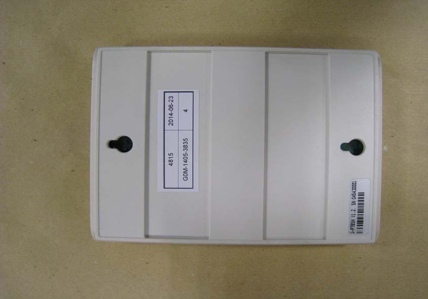
Click to zoom
Application Details
- Equipment Class
- PUB - Part 15 Unlicensed PCS Base Station
- Date of Grant
- Jul 14, 2014
- Application Purpose
- Original Equipment
- Date of Application
- Jul 14, 2014
- Equipment Note
- Dect Wireless Communication
- Frequency Range
- 1921.53600000 - 1928.44800000
- Company
- Quail Ltd.
- Country
- United Kingdom
Documents & Files
Document Text
Text extracted from the exhibit documents filed with the FCC. Open a document above to read the original.
Users Manual
Installation Manual This manual is aimed at a technical level reader who is expected to be familiar with all safety precautions relevant to the use of electrical and electronic equipment. This system operates with 48v DC power supply. To maintain warranty only Quail Digital approved parts should be used.Do not attempt to power the Quail Digital Pro7 Headset System using Power over Ethernet (PoE) adaptors, as they may cause damage to the Base Station. |page 2 Contents System Overview 4 Q-P7BS - Pro7 Base 5 Q-P7HS - Pro7 Headset 7 Q-P7CH - Pro7 Charger 8 Q-P7MK12 - Pro7 12 Button Keypad 8 System Installation 9 Deciding how many Bases 9 Installation rules 10 RJ45 wiring 10 Remote registration switch 11 Registering the headsets 12 Locating the charger 12 Keypad installation 13 System Test 16 System Specification 18 |page 3 System Overview Quail Digital Pro7system is a DECT wireless headset system using multiple Bases Stations (Bases) to cover large areas with up to 30 wireless headsets. Once the headsets are registered to the Base/s they all listen and up to 6 users talk simultaneously. The system allows the configuration of a large DECT wireless network, connected and powered via Cat5 cable giving the flexibility to position Bases for wide area, multi-room, multi floor coverage. Up to 20 bases can be deployed on the same network. Interconnecting Bases use Cat5 cable for power and data transmission. The system can be used in conjunction with wireless keypads for transmission of pre-recorded messages activated from keypads or other device to the headsets. Keypads are mainly used at tills and call points in retail applications to transmit assistance messages. All headsets hear all the messages. The standard range for each base is 50 metres (150ft) from the Base inside and up to 100 metres (300ft) in open spaces. Internal walls, partitions, building fabrics and ceiling heights can affect range. |page 4 Q-P7BS - Pro7 Base Station The Q-P7BS Base is a DECT wireless transceiver (license free) which is powered by an external 48 Volt DC universal power supply. The Base can be networked with multiple Bases (20 max) using standard Cat5 network cable and RJ45 connectors. To connect Bases use the standard network configuration type B (see from page 9). The 48 DC Volts is provided to the Base with the QD mains adaptor or from the network cable connected on the RJ45 “A” socket. The headsets need to pair with the Base(s). The pairing process is referred to as registration. Each headset needs to be registered to the system. Headsets can be added or removed at any time by going through the registration process (see page 12). When the registration process is completed the network will automatically update the registry across all the Bases on the network. There are two LEDs in the front panel of the Base which indicate its status at any time. |page 5 Registration Button Cat5 Out Cat5 In Power adaptor Micro SD card Message volume For registration: press for 5 secs To reset: press for 15 secs Front Power and Status LEDs Base Station Bottom Top Q-P7BS Base functions Registration button and registration socket This button allows you to put the Base into registration mode. Use a pencil or narrow tipped screwdriver to activate the button in the housing of the Base. Press the registration button for 5 seconds to enter this mode. Pressing the wall mounted registration socket for 5 seconds does the same. Resetting the Base or network The Base should be reset or ‘synchronised’ whenever additional bases are added or when the system is reconfigured for any reason or when the SIMcard is updated. To reset the system pressing the registration button on the master Base, or the wall mounted registration button for 15 seconds, which resets the complete network. Don’t reset the Base by removing the power adapter, it will only reset the bases supplied from that particular socket. Micro SD card This card is used to store the WAV audio files triggered by the remote keypads. For instructions on recording the audio files, naming protocol and programming of the keypads refer to page 15. Only use SanDisk MicroSD cards, formatted as Fat32, file size allocation 4096. Keypad messages The Base is fitted with an FM receiver for communication with the remote keypads. Up to 256 keypads can work with one single base or network. For the recording of audio files, naming protocol and programming refer to the system installation section. Message volume adjustment The volume adjustment is located at the bottom of the Base. This increases/decreases the audio level of the messages played in the headsets. Use a thin flat tipped screwdriver and gently turn to the right to increase the volume and to the left, to decrease. RJ45 networking sockets Use these two sockets on the top of the base to network two or more bases. |page 6 POWER LEDSTATUS LED B ooting up Base is master and ready B ase is slave and ready S ynchronization signal receiving OK Active call or calls on this Base BOTH LEDs FLASHINGCORRECTIVE ACTION Power too low to boot upCheck the individual power supplies o n the network for possible failure; or b eing switched off; or consider adding an extra power supply to the network Base in registration modeThe system will time-out of this mode in 10 minutes but you can press the registration switch to exit the registration mode manually Q-P7HS - Pro7 Headset The headset can be worn on either ear. The headset is available with a headband or neckband. Volume:There are 5 volume settings. Use the toggle at the rear of the headset to adjust volume by pressing upwards for each step. Speech:The headset can be used in 2 speech modes, TalkLock, and PTT (push to talk). TalkLock:This mode puts the headset in hands free mode. To activate, press the silver button for less than 1 second, the headset is then hands-free, to deactivate it, press silver button again. This will shut off microphone. PTT:Press silver button while you are talking, release when finished.…
Text truncated - open the document above for the full version.
Users Manual
User guide PRO7 HEADSET SYSTEM If your installation requires more than one Base you will require Cat5 cable, two or more RJ45 plugs and crimping tool - and a LAN + RJ45 network cable tester. These installation instructions are aimed at a person with a reasonable level of technical competence and familiar with the safety precautions relevant to the use of electrical and electronic equipment. You should not attempt to install this system without the relevant level of expertise. This system operates with a 48v DC power supply. To maintain warranty, only Quail Digital approved parts should be used. PRO7 HEADSET SYSTEM The Base Station (Base) is a license-free DECT wireless transceiver using a 48v DC external power supply. The system can be expanded with multiple Bases, up to a maximum of 20, in a closed communications network linked by Cat5 cable. The typical range of the Base is up to 50 meters internally and up to 100 meters in open spaces. Internal walls, stairwells, partitions, building fabrics and room height can affect range. Installing single or multiple Bases The diagram below illustrates possible locations to mount your Base. As a tip always locate a Base where it has maximum direct sight of the area you want to cover. Before fixing your installation permanently, you could also place the Base in temporary locations around the premises to test and optimize coverage. You should also identify the location of power sockets and routes for Cat5 cables if you intend to use multiple Bases. Installing the system 3 Locating your Base 3 Good location 7 Bad location partition pillar If you plan to mount the Base higher than 2m above floor level consider installing a Registration Button- it should be wall- mounted underneath the Base so you can see the Base LEDs during the registration process. The Registration Button is used to activate the registration process (press for five seconds) and to reset the entire network (press for 15 seconds). PRO7 HEADSET SYSTEM Registration Button Cat5 Out Cat5 In Power adaptor Micro SD card Message volume For registration: press for 5 secs To reset: press for 15 secs 4m 2m 0m Base Registration Button Power Status Base Station Bottom Top Useful Tip Power to the Bases should use a constant 24hr power outlet. If one or more mains circuits is switched off, it may affect the operation of the entire Base network. Follow the Type B wiring protocol for all RJ45 plugs Colour code as shown right. Rules when installing multiple Bases on the same network • Ideal height for Bases is between 2 and 4 meters above floor level. • The maximum cable length between any two Bases should not exceed 100m. • The maximum cable length between two power sources should not exceed 200m. • The maximum number of Bases a single power supply should support is four. • When ‘mapping’ the premises, as a general rule place the next Base 10m beyond the point where the headset loses range from the previous Base. • It is good practice to label the Cat5 cables that go into the top of the Base IN and OUT respectively to avoid mis-connection at a later date. 5 The two LEDs on the front of the Base indicate its status, as below: PRO7 HEADSET SYSTEM POWER LEDSTATUS LED Booting up Base is master and ready Base is slave and ready Synchronization signal receiving OK Active call or calls on this Base BOTH LEDs FLASHINGCORRECTIVE ACTION Power too low to boot upCheck the individual power supplies on the network for possible failure; or being switched off; or consider adding an extra power supply to the network Base in registration modeThe system will time-out of this mode in 10 minutes but you can press the registration switch to exit the registration mode manually The Headset Charger should be positioned on a worktop and plugged into a socket that is a constant 24hr power outlet. The charger should be located within range of a Base so that headsets remain active at all times. Return headsets to the charger when not in use. Charge time is approximately 2.5 hours. When charging, the blue light on the headset will flash every five seconds. When fully charged the blue light is constant. Headsets will last up to 8 hours between charges, slightly less in TalkLock mode. 3 beeps every 60 seconds indicate the battery is getting low. Positioning the charger 7 Each headset needs to be registered to the system for the first time before use. The system has the capacity for 30 headsets. To register one or more headsets, follow this procedure: 1 Make sure the new headset has a charged battery (blue LED flashes every five seconds). 2 Make sure all the headsets in use with the system are in range of the Base. If a headset isn’t in range of the Base during the registration process it will be deleted from the system. 3 Put the Base in ‘registration mode’ by pressing the Registration Button on the Base, or by pressing the wall-mounted Registration Button, for five seconds. On the Base both LEDs should be flashing green. 4 Place the new headset to your ear, press the large silver button and volume toggle down for three seconds. Wait for the bleeps to change their frequency and tone to one bleep every second. 5 A three second long bleep signifies successful registration. You may also hear a double bleep tone that will indicate it is ready to use. 6 As soon as a headset is registered, it is ready to use. Press the Registration Button again to exit the registration process or leave it to time-out after 10 minutes. Registering and using headsets PRO7 HEADSET SYSTEM Volume There are five volume settings. Use the toggle at the rear of the headset to adjust volume by pressing upwards for each step. Speech The headset can be used in two speech modes: - TalkLockThis mode is hands-free. To activate, press the silver button for less than one second - the headset is then hands- free. To de-activate it, press the silver button again. This will shut off the microphone. -PTTPress the silver button while you are talking, then release when finishe…
Text truncated - open the document above for the full version.
External Photos
External Photos page 1 Model No.:Q-P7BS FCC ID: UDDQP7BS IC: 6402A-QP7BS Project No.: G0M-1405-3835-TFC15DFP-V01 External Photos page 2 Model No.:Q-P7BS FCC ID: UDDQP7BS IC: 6402A-QP7BS Project No.: G0M-1405-3835-TFC15DFP-V01
ID Label/Location Info
LABELING AND MARKING Q-P7BS LABELING Pro7 Base Station Sample Q-P7BS Labels Q-P7BS Labels Locations
Internal Photos
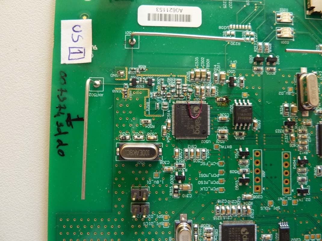
Internal Photos page 1 Model No.:Q-P7BS FCC ID: UDDQP7BS IC: 6402A-QP7BS Project No.: G0M-1405-3835-TFC15DFP-V01
RF Exposure Info
Test Report No.: G0M-1405-3835-TFC091ME-V01 Eurofins Product Service GmbH Storkower Str. 38c, D-15526 Reichenwalde, Germany Page 1 of 12 RF-EXPOSURE ASSESSMENT REPORT FCC 47 CFR Part 2.1091 Industry Canada RSS-102 RF-Exposure evaluation of mobile equipment Report Reference No. ..................... : G0M-1405-3835-TFC091ME-V01 Testing Laboratory ......................... : Eurofins Product Service GmbH Address............................................. : Storkower Str. 38c 15526 Reichenwalde Germany Accreditation ..................................... : A2LA Accredited Testing Laboratory, Certificate No.: 1983.01 FCC Filed Test Laboratory, Reg.-No.: 96970 IC OATS Filing assigned code: 3470A Applicant’s name ............................ : Quail Digital UK Address............................................. : 92 Lots Road SW10 0QD London UNITED KINGDOM Test specification: Standard ........................................... : 47 CFR 1.1310 / 47 CFR 2.1091 / 47 CFR 2.1093 OET Bulletin 65:1997 RSS-102, Issue 4:2010 Safety Code 6:2009 Equipment under test (EUT): Product description DECT Base Station for Intercommunication use Model No. Q-P7BS Additional Model(s) None Brand Name(s) Quail Hardware version revB Firmware / Software version 1.2.0 FCC-ID: UDDQP7BS IC: 6402A-QP7BS Test result Passed Test Report No.: G0M-1405-3835-TFC091ME-V01 Eurofins Product Service GmbH Storkower Str. 38c, D-15526 Reichenwalde, Germany Page 3 of 12 Version History Version Issue Date Remarks Revised by 01 2014-07-09 Initial Release Test Report No.: G0M-1405-3835-TFC091ME-V01 Eurofins Product Service GmbH Storkower Str. 38c, D-15526 Reichenwalde, Germany Page 4 of 12 REPORT INDEX 1 EQUIPMENT (TEST ITEM) DESCRIPTION 5 1.1 Reference Documents 6 1.2 Radiation Sources 7 2 RESULT SUMMARY 8 3 RF-EXPOSURE CLASSIFICATIONS 9 4 ASSESSMENT 10 4.1 MPE Assessment – 47 CFR 2.1091 / RSS-102 10 Test Report No.: G0M-1405-3835-TFC091ME-V01 Eurofins Product Service GmbH Storkower Str. 38c, D-15526 Reichenwalde, Germany Page 5 of 12 1 Equipment (Test item) Description Description DECT Base Station for Intercommunication use Model Q-P7BS Additional Model(s) None Brand Name(s) Quail Serial number N/A Hardware version revB Software / Firmware version 1.2.0 FCC-ID UDDQP7BS IC 6402A-QP7BS Equipment type End product Test Report No.: G0M-1405-3835-TFC091ME-V01 Eurofins Product Service GmbH Storkower Str. 38c, D-15526 Reichenwalde, Germany Page 6 of 12 1.1 Reference Documents Document type Document No. Issued by Date FCC 15D Test Report G0M-1405-3835-TFC091ME-V01 Eurofins Product Service GmbH 2014-07-09 Test Report No.: G0M-1405-3835-TFC091ME-V01 Eurofins Product Service GmbH Storkower Str. 38c, D-15526 Reichenwalde, Germany Page 7 of 12 1.2 Radiation Sources Mode # Description UPCS Frequency range [MHz] 1921.536 – 1928.448 Channels 5 Transmission modes TDMA Modulations GFSK Maximum radiated power [dBm] 20.60 Maximum transmission duty cycle [%] 25 Antenna gain [dBi] 2.0 Antenna diameter [cm] 4 Test Report No.: G0M-1405-3835-TFC091ME-V01 Eurofins Product Service GmbH Storkower Str. 38c, D-15526 Reichenwalde, Germany Page 8 of 12 2 Result Summary FCC 47 CFR Part 2.1091, IC RSS-102 Product Specific Standard Section Requirement Result Remarks 47 CFR 2.1091 Maximum permissible exposure @ 20cm below limit PASS RSS-102 2.5.2 Maximum permissible exposure @ 20cm below limit PASS Remarks: Test Report No.: G0M-1405-3835-TFC091ME-V01 Eurofins Product Service GmbH Storkower Str. 38c, D-15526 Reichenwalde, Germany Page 9 of 12 3 RF-Exposure Classifications Device Types Fixed A fixed device is defined as a device physically secured at one fixed location and cannot be easily re-located. Mobile A mobile device is defined as a transmitting device designed to be used in other than fixed locations and to generally be used in such a way that a separation distance of at least 20 centimeters is normally maintained between the transmitter's radiating structure(s) and the body of the user or nearby persons. (47 CFR 2.1091) Portable A portable device is defined as a transmitting device designed to be used so that the radiating structure(s) of the device is/are within 20 centimeters of the body of the user. (47 CFR 2.1093) Exposure Categories Occupational / Controlled Limits apply in situations in which persons are exposed as a consequence of their employment provided those persons are fully aware of the potential for exposure and can exercise control over their exposure. Limits for occupational/controlled exposure also apply in situations when an individual is transient through a location where occupational/controlled limits apply provided he or she is made aware of the potential for exposure. General population / uncontrolled Exposures apply in situations in which the general public may be exposed, or in which persons that are exposed as a consequence of their employment may not be fully aware of the potential for exposure or cannot exercise control over their exposure. Test Report No.: G0M-1405-3835-TFC091ME-V01 Eurofins Product Service GmbH Storkower Str. 38c, D-15526 Reichenwalde, Germany Page 10 of 12 4 Assessment 4.1 MPE Assessment – 47 CFR 2.1091 / RSS-102 MPE Assessment acc. to 47 CFR 2.1091 / IC RSS-102 Verdict: PASS Assessment according to reference Reference Method FCC OET Bulletin 65 / RSS-102 & Safety Code 6 Device type mobile Exposure category General public IC Limits – Occupational / Controlled Exposure Frequency range [MHz] Electric field strength [V/M] Magnetic field strength [A/M] Power density [W/m 2 ] Averaging time [min] 0.003 – 1.0 600 4.9 N/A 6 1 – 10 600/f 4.9/f N/A 6 10 – 30 60 4.9/f N/A 6 30 – 300 60 0.163 10.0* 6 300 – 1500 3.54·f 0.5 0.0094·f 0.5 f/30 6 1500 - 15000 137 0.364 50 6 15000 - 150000 137 0.364 50 616000/f 0.5 150000 - 300000 0.354·f 0.5 9.4·10 -4 ·f 0.5 3.33·10 -4 ·f 616000/f 0.5 IC Limits – General Population / Uncontrolled Exposure Frequency range [MHz] Electric field strength [V/M] Magnetic field strength [A/M] Power density…
Text truncated - open the document above for the full version.
Test Report
Test Report No.: G0M-1405-3835-TFC15DFP-V01 Eurofins Product Service GmbH Storkower Str. 38c, D-15526 Reichenwalde, Germany Page 1 of 114 FCC TEST REPORT FCC 47 CFR Part 15D Unlicensed Personal Communication Service Devices Industry Canada RSS-213 2GHz License-exempt Personal Communications Service Devices (LE-PCS) Report Reference No. ..................... : G0M-1405-3835-TFC15DFP-V01 Testing Laboratory ......................... : Eurofins Product Service GmbH Address............................................. : Storkower Str. 38c 15526 Reichenwalde Germany Accreditation ..................................... : A2LA Accredited Testing Laboratory, Certificate No.: 1983.01 FCC Filed Test Laboratory, Reg.-No.: 96970 IC OATS Filing assigned code: 3470A Applicant’s name ............................ : Quail Digital UK Address............................................. : 92 Lots Road SW10 0QD London UNITED KINGDOM Test specification: Standard ........................................... : 47 CFR Part 15D 47 CFR Part 15C 47 CFR Part 15B RSS-213, Issue 2, 2005-12 RSS-Gen, Issue 3, 2010-12 ANSI C63.17:2006 ANSI C63.4:2003 Equipment under test (EUT): Product description DECT Base Station for Intercommunication use Model No. Q-P7BS Additional Model(s) None Brand Name(s) Quail Hardware version revB Firmware / Software version 1.2.0 FCC-ID: UDDQP7BS IC: 6402A-QP7BS Test result Passed Test Report No.: G0M-1405-3835-TFC15DFP-V01 Eurofins Product Service GmbH Storkower Str. 38c, D-15526 Reichenwalde, Germany Page 3 of 114 Version History Version Issue Date Remarks Revised by 01 2014-07-09 Initial Release Test Report No.: G0M-1405-3835-TFC15DFP-V01 Eurofins Product Service GmbH Storkower Str. 38c, D-15526 Reichenwalde, Germany Page 4 of 114 REPORT INDEX 1 EQUIPMENT (TEST ITEM) DESCRIPTION 6 1.1 Photos - Equipment external 8 1.2 Photos - Equipment internal 10 1.3 Photos – Test setup 12 1.4 Supporting Equipment Used During Testing 13 1.5 Test Modes: 14 1.6 Test Equipment Used During Testing 15 1.7 Sample emission level calculation 16 2 RESULT SUMMARY 17 3 TEST CONDITIONS AND RESULTS 19 3.1 Test Conditions and Results – Coordination with fixed microwave service 19 3.2 Test Conditions and Results – Cross reference to subpart B 20 3.3 Test Conditions and Results – AC power line conducted emissions 21 3.4 Test Conditions and Results – Antenna requirement 24 3.5 Test Conditions and Results – Digital modulation 25 3.6 Test Conditions and Results – Occupied Bandwidth 26 3.7 Test Conditions and Results – Emission Bandwidth 30 3.8 Test Conditions and Results – Peak transmit power 33 3.9 Test Conditions and Results – Power spectral density 37 3.10 Test Conditions and Results – Frequency stability 40 3.11 Test Conditions and Results – Transmitter in-band unwanted emissions 46 3.12 Test Conditions and Results – Transmitter out-of-band emissions 50 3.13 Test Conditions and Results – Receiver spurious emissions 79 3.14 Test Conditions and Results – Automatic discontinuation of Transmission 89 3.15 Test Conditions and Results – Radiofrequency radiation exposure 90 3.16 Test Conditions and Results – Monitoring threshold 91 3.17 Test Conditions and Results – LIC confirmation 93 3.18 Test Conditions and Results – LIC selection 94 3.19 Test Conditions and Results – Monitoring antenna 95 3.20 Test Conditions and Results – Monitoring time 97 3.21 Test Conditions and Results – Monitoring bandwidth 98 3.22 Test Conditions and Results – Monitoring reaction time 99 3.23 Test Conditions and Results – System acknowledgement 101 3.24 Test Conditions and Results – Random waiting 104 Test Report No.: G0M-1405-3835-TFC15DFP-V01 Eurofins Product Service GmbH Storkower Str. 38c, D-15526 Reichenwalde, Germany Page 5 of 114 3.25 Test Conditions and Results – Maximum transmit period 108 3.26 Test Conditions and Results – Maximum spectral occupancy 109 3.27 Test Conditions and Results – Fair access 110 3.28 Test Conditions and Results – Frame period and Jitter 111 3.29 Test Conditions and Results – Frame and TDMA repetition stability 113 Test Report No.: G0M-1405-3835-TFC15DFP-V01 Eurofins Product Service GmbH Storkower Str. 38c, D-15526 Reichenwalde, Germany Page 6 of 114 1 Equipment (Test item) Description Description DECT Base Station for Intercommunication use Model Q-P7BS Additional Model(s) None Brand Name(s) Quail Serial number N/A Hardware version revB Software / Firmware version 1.2.0 FCC-ID UDDQP7BS IC 6402A-QP7BS Equipment type Radio Module Radio type DECT Fixed Part Number of Radios 2 identical transceivers is built into the device Radio technology DECT 6.0 Operating frequency range 1921.536 - 1928.448MHz Assigned frequency band 1920 - 1930MHz Number of RF channels 5 Supported slots even only Number of time slots 12 x Tx + 12 x RX = 24 Channels F 0 Ch:0 / 1928.448 MHz F 1 Ch:1 / 1926.720 MHz F 2 Ch:2 / 1924.992 MHz F 3 Ch:3 / 1923.264 MHz F 4 Ch:4 / 1921.536 MHz Main test frequencies F LOW Ch:4 / 1921.536 MHz F MID Ch:2 / 1924.992 MHz F HIGH Ch:0 / 1928.448 MHz Modulations GFSK Emission designator F7D Channel spacing 1728 kHz Spectrum access Listen before transmit Nominal lower threshold N/A Nominal upper threshold -63 dBm Number of antennas 2 per transceiver Test Report No.: G0M-1405-3835-TFC15DFP-V01 Eurofins Product Service GmbH Storkower Str. 38c, D-15526 Reichenwalde, Germany Page 7 of 114 Antenna 1 Type integrated Model wire antenna Manufacturer see Manufacturer Gain 2 dBi Antenna 2 Type integrated Model wire antenna Manufacturer see Manufacturer Gain 2 dBi Manufacturer Quail Digital UK 92 Lots Road SW10 0QD London UNITED KINGDOM Power supply V NOM 48 VDC V MIN 45 VDC V MAX 49 VDC AC/DC-Adaptor Model N/A Vendor N/A Input N/A Output N/A Temperature T NOM 25°C T MIN 0°C T MAX 40°C Test Report No.: G0M-1405-3835-TFC15DFP-V01 Eurofins Product Service GmbH Storkower Str. 38c, D-15526 Reichenwalde, Germany Page 8 of 114 1.1 Photos - Equipment external EUT OVERVIEW EUT BOTTOM Test Report No.: G0M-1405-3835-TFC15DFP-V01 Eurofins P…
Text truncated - open the document above for the full version.
Test Setup Photos
T-Sup Photos page 1 Model No.:Q-P7BS FCC ID: UDDQP7BS IC: 6402A-QP7BS Project No.: G0M-1405-3835-TFC15DFP-V01
Contact Information
Applicant
Jose Barrera Guerrero(Technical Manager)
Technical Contact
Test Firm
Eurofins Product Service GmbHRobert Kschiwan-Kaspar
Technical Specifications
| # | Rule Parts | Frequency Range | Power Output | Tolerance |
|---|---|---|---|---|
| 1 | 15D | 1.92 GHz - 1.93 GHz | 120.00 mW | ppm |
Other Applications from Quail Ltd.
UDDQP11BS
Jul 04, 2021DECT Base station
Equipment Class
PUB - Part 15 Unlicensed PCS Base Station
UDDQP9BS
Jan 05, 2021Quail Pro 9 Base Station
Equipment Class
PUB - Part 15 Unlicensed PCS Base Station
UDDQP10HS
Nov 24, 2020DECT headset
Equipment Class
PUE - Part 15 Unlicensed PCS portable Tx held to ear
UDDQDTB
Jan 29, 2013Q-DTB (QD Drive Thru Base)
Equipment Class
PUB - Part 15 Unlicensed PCS Base Station
UDDQDT8
Jan 29, 2013Q-DT8 (QD Drive Thru Headset)
Equipment Class
PUE - Part 15 Unlicensed PCS portable Tx held to ear