UDDQP11BSDECT Base station
Quail Ltd.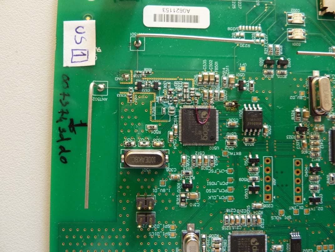
Click to zoom
Application Details
- Equipment Class
- PUB - Part 15 Unlicensed PCS Base Station
- Date of Grant
- Jul 04, 2021
- Application Purpose
- Original Equipment
- Date of Application
- Jul 04, 2021
- Equipment Note
- DECT Base station
- Frequency Range
- 1921.53600000 - 1928.44800000
- Company
- Quail Ltd.
- Country
- United Kingdom
Documents & Files
Document Text
Text extracted from the exhibit documents filed with the FCC. Open a document above to read the original.
Users Manual
Pro11 Headset System Installation Manual Pro11 Headset Q-P11HS Pro11 Base Station Q-P11BS Pro11 Charger Q-P11CH STEP 1 • The base station can be located in either the OR or the monitoring room. • Identify a location with clear space around it and nothing in front (the base is a transmitter). (figure 1) • You need a power socket close by. Connect the Q-PSU48 power supply into the wall socket and then into the socket in the top of the base. • The base should be fitted to the wall using the two velcro strips supplied, peeling back the protective covers. Do not fit the base to the wall upside down or sideways. • When the power is connected, the LED on the front will start AMBER during booting up, then go GREEN after 30 secs. STEP 2 • Set up the 6-port battery charger. Select a clear desk or cabinet top in the monitoring room close to a power socket that DOESN’T get switched off or unplugged at night. (figure 2) • Connect the Q-PSU5 power supply into the back of the charger and weave the cable around the gates. (figure 3) • Switch on the power. The LED on the front of the charger will illuminate GREEN. figure 2 figure 3 figure 1 STEP 3 • Place a battery into each headset, by removing the outer sleeve on the body of the headset using your fingernail. (figure 4) • Remove the tape over the battery contacts, then slot the battery into the chamber. It only goes in one way, so turn it over if it won’t slide in. Clip the sleeve back on. As soon as the battery is connected the LED will flash BLUE every second. • Place all headsets into the charger. The headsets are now charging. The LED on the headset will flash BLUE every 10 seconds. STEP 4 • To register a headset to the base station, take one headset at a time out of the charger and hold the outside face of the headset to the bottom of the base. (figure 5) • As soon as you do this, the LED on the base will flash AMBER, and then go solid AMBER, which means the headset is registered. Place the headset back in the charger and repeat the process with the next one. • Leave all headsets in the charger for 2 minutes to synchronise with each other. • To test, put on a headset, press the talk button and speak into the headset - if you can hear your own voice, the headset is working and ready for use. (figure 6) • To use a headset in ‘hands-free’ mode, press the talk button for a second; the blue LED will remain on, indicating that you are hands-free. To use in normal ‘Push-To- Talk’ mode, remove your finger from the talk button when you finish speaking. To change volume, press the volume button; it has 5 levels. figure 4 figure 5 figure 6 Customer support • www.quaildigital.com/video/QD-Pro11-installation.mp4 Headset audioStatusNext steps Bloop-bleepCall dropEither you’ve moved out of range of base (move towards it), or base has no power (check LED on front of base). If LED out, call Tech support. 2 beeps every 10 secondsOut of rangeHeadset is not in range of base (move towards it), or base has no power (check LED on front of base). If LED out, call Tech support. 3 beeps every 60 secondsBattery lowPut headset in charger and take another headset. 1 beep every 3 seconds (and fast flashing LED) Registration requiredHeadset is working but needs to be registered to the system. Fault/symptomsAction Headset has been in charger, but LED isn’t flashing Determine whether it’s a headset or battery fault. Swap the battery from one in a working headset. If changing the battery clears the fault, then throw away the faulty battery and order a new one. If not, send the headset back for repair/replacement. Headset LED is pulsing as normal every 4 seconds but audio not working’ Put the headset back into the charger for at least 10 seconds. This should reset the headset. If it doesn’t, remove the battery from the headset then replace it again. If this doesn’t clear the fault, send the headset back for repair/ replacement. Headset functionality and system troubleshooting Useful information • If you have multiple ORs and multiple Pro11 systems you can move headsets from one room to another by following Step 4 overleaf. When a headset is registered to another base station it automatically deregisters from the previous one. • If you hear 2 beeps in your ear, it means you’ve gone out of range. Move back towards the base station it’s registered to and the headset will reconnect. • Batteries will last for 16 hours on standby and up to 10 hours in hands-free mode. Always put headsets back into the charger when not in use. • Wipe down headsets and charger with hygiene wipes routinely. • Call your service provider if you have any problems. Regulatory Notices Headset - HVIN: Q-P11HS FCC ID: UDDQP10HS This device complies with Part 15 of the FCC Rules. Operation is subject to the following two conditions: (1) This device may not cause harmful interference, and (2) this device must accept any interference received, including interference that may cause undesired operation. Changes or modifications not expressly approved by the party responsible for compliance could void the user’s authority to operate the equipment. This equipment complies with FCC radiation exposure limits set forth for an uncontrolled environment. Note: This equipment has been tested and found to comply with the limits for a Class B digital device, pursuant to part 15 of the FCC Rules. These limits are designed to provide reasonable protection against harmful interference in a residential installation. This equipment generates, uses and can radiate radio frequency energy and, if not installed and used in accordance with the instructions, may cause harmful interference to radio communications. However, there is no guarantee that interference will not occur in a particular installation. If this equipment does cause harmful interference to radio or television reception, which can be determined by turning the equipment off and on, the user is encouraged to try to correct the interference by one or more of the following meas…
Text truncated - open the document above for the full version.
External Photos
2019-08-26 Page 1 of 5 Annex A: Photographs of the Test Set-up Photo 1: Radiated Emission Photo 2: Radiated Emission Test report no.: 1-7183/18-03-07 2019-08-26 Page 2 of 5 Annex B: External Photographs of the EUT Photo 1: Photo 2: Test report no.: 1-7183/18-03-07 2019-08-26 Page 3 of 5 Photo 3: Test report no.: 1-7183/18-03-07 2019-08-26 Page 4 of 5 Annex C: Internal Photographs of the EUT Photo 1: Photo 2: Test report no.: 1-7183/18-03-07 2019-08-26 Page 5 of 5 Photo 3:
Internal Photos
2019-08-26 Page 1 of 5 Annex A: Photographs of the Test Set-up Photo 1: Radiated Emission Photo 2: Radiated Emission Test report no.: 1-7183/18-03-07 2019-08-26 Page 2 of 5 Annex B: External Photographs of the EUT Photo 1: Photo 2: Test report no.: 1-7183/18-03-07 2019-08-26 Page 3 of 5 Photo 3: Test report no.: 1-7183/18-03-07 2019-08-26 Page 4 of 5 Annex C: Internal Photographs of the EUT Photo 1: Photo 2: Test report no.: 1-7183/18-03-07 2019-08-26 Page 5 of 5 Photo 3:
RF Exposure Info
© CTC advanced GmbH Page 1 of 3 D-PL-12076-01-03 Maximum Permissible Exposure (MPE) & Exposure evaluation Report identification number: 1-7183/18-03-04 MPE (FCC_ISED) Certification numbers and labeling requirements FCC ID UDDQP11BS ISED number 6402A-QP11BS HVIN (Hardware Version Identification Number) Q-P11BS PMN (Product Marketing Name) Pro11 Headset System FVIN (Firmware Version Identification Number) -/- HMN (Host Marketing Name) -/- This report is electronically signed and valid without handwriting signature. For verification of the electronic signatures, the public keys can be requested at the testing laboratory. Document authorised: p.o. Alexander Hnatovskiy Marco Scigliano Lab Manager Testing Manager Radio Communications & EMC Radio Communications & EMC Report no.: 1-7183/18-03-04 © CTC advanced GmbH Page 2 of 3 EUT technologies: Technologies: Max. power: (PEAK) Max. antenna gain: Max duty cycle: UPCS 1925 (Base station module) Declared 17 dBm Declared : 2.0 dBi 3 of 24 Slots 12.25% NOTE: 2 modules operating at the same time (max. Uplink: 6 FULL SLOTS – duty cycle 25%) Prediction of MPE limit at given distance - FCC Equation from page 18 of OET Bulletin 65, Edition 97-01 S = PG / 4 π R 2 where: S = Power density P = Power input to the antenna G = Antenna gain R = Distance to the center of radiation of the antenna PG = Output Power including antenna gain The table below is excerpted from Table 1B of 47 CFR 1.1310 titled “Limits for Maximum Permissible Exposure (MPE), Limits for General Population/Uncontrolled Exposure” Frequency Range (MHz) Power Density (mW/cm 2 ) Averaging Time (minutes) 300 -1500 f/1500 30 1500 - 100000 1.0 30 where f = Frequency (MHz) Prediction: worst case Technologies: Module 1 Module 2 Frequency (MHz)19251925 PG Declared max power (EIRP)1111dBm RDistance20 20cm SMPE limit for uncontrolled exposure1 1 mW/cm 2 Calculated Power density:0.00250.0025 mW/cm² Calculated percentage of Limit: 0.25%0.25% Both modules active Calculated percentage of Limit: 0.50% Collocation: The power density levels for FCC at a distance of 20 cm are below the maximum levels allowed by regulations. Report no.: 1-7183/18-03-04 © CTC advanced GmbH Page 3 of 3 Prediction of MPE limit at given distance - ISED RSS-102, Issue 5, 2.5.2 RF exposure evaluation is required if the separation distance between the user and/or bystander and the device’s radiating element is greater than 20 cm, except when the device operates as follows: • below 20 MHz and the source-based, time-averaged maximum e.i.r.p. of the device is equal to or less than 1 W (adjusted for tune-up tolerance); • at or above 20 MHz and below 48 MHz and the source-based, time-averaged maximum e.i.r.p. of the device is equal to or less than 4.49/ƒ 0.5 W (adjusted for tune-up tolerance), where ƒ is in MHz; • at or above 48 MHz and below 300 MHz and the source-based, time-averaged maximum e.i.r.p. of the device is equal to or less than 0.6 W (adjusted for tune-up tolerance); • at or above 300 MHz and below 6 GHz and the source-based, time-averaged maximum e.i.r.p. of the device is equal to or less than 1.31 x 10 -2 ƒ 0.6834 W (adjusted for tune-up tolerance), where ƒ is in MHz; • at or above 6 GHz and the source-based, time-averaged maximum e.i.r.p. of the device is equal to or less than 5 W (adjusted for tune-up tolerance). Prediction: worst case Module 1Module 2 Frequency 19251925MHz RDistance 2020 cm PMax power input to the antenna 1111 dBm G Antenna gain2 2dBi PG Maximum EIRP13 13 dBm P G Maximum EIRP 20.020.0mW Exclusion Limit from above: 2.302.30 W Calculated percentage of Limit: 0.87%0.87% Both modules active Calculated percentage of Limit: Collocation: 1.73% Conclusion: RF exposure evaluation is not required.
Test Report
2021-06-30 Page 1 of 59 TEST REPORT Test Report No.: 1-7183/18-03-07-A Testing Laboratory Applicant CTC advanced GmbH Untertürkheimer Straße 6 – 10 66117 Saarbrücken/Germany Phone: + 49 681 5 98 - 0 Fax: + 49 681 5 98 - 9075 Internet: http://www.ctcadvanced.com e-mail: [email protected] Accredited Test Laboratory: The testing laboratory (FCC part 15 D) is accredited according to DIN EN ISO/IEC 17025 (2005) by the Deutsche Akkreditierungsstelle GmbH (DAkkS) The accreditation is valid for the scope of testing procedures as stated in the accreditation certificate with the registration number: D-PL-12076-01-04 / -05 Quail Digital Unit 6 92 Lots Road Chelsea, London, SW10 0QD , United Kingdom Phone: +44 (0) 207 349 2000 Fax: +44 (0) 207 349 2045 Contact: Stephen Head e-mail: [email protected] Manufacturer Active PCB Acre Road RG2 0SU, Reading United Kingdom Test Standard/s FCC Part 15, subpart D: 2016 Isochronous UPCS Device 1920 – 1930 MHz Industry Canada RSS-213, Issue 3: 2015 2 GHz Licence-exempt Personal Communication Service Devices (LE-PCS) Test Item Kind of product: DECT headset system Product name: Pro 11 base station HVIN: PMN: FVIN: HMN: FCC ID: Q-P11BS Pro11 Headset System N/A N/A UDDQP11BS IC: 6402A-QP11BS S/N serial number: Radiated: Q731920002 Conducted: Q731920001 HW hardware status: rev. A1 SW software status: 1.0.0. NA Frequency [MHz]: 1920 -1930 Type of Modulation: Digital (Gaussian Frequency Shift Keying) Number of channels: 5 RF Channels, 5x12 = 60 TDMA Duplex Channels Antenna: 4 integrated antennas Power Supply: 48 V DC Temperature Range: -20°C to 50°C Test Report authorised: Test performed: 2021-06-30 Michael Dorongovski 2021-06-30 Wolf, Joachim Lab Manager Radio Communications Head of Department EPNS Test report no.: 1-7183/18-03-07-A 2021-06-30 Page 2 of 59 1 Table of contents 1 Table of contents ......................................................................................................................................... 2 2 General information .................................................................................................................................... 4 2.1 Notes and disclaimer ....................................................................................................................... 4 2.2 Application details ........................................................................................................................... 4 3 Test standard/s: ........................................................................................................................................... 4 4 Test Environment ........................................................................................................................................ 5 5 Summary of Measurement Results ........................................................................................................... 6 6 Test Set-up ................................................................................................................................................... 7 6.1 Frequency Measurements ............................................................................................................... 7 6.2 Timing Measurements ..................................................................................................................... 7 6.3 Conducted Emission Test ............................................................................................................... 7 6.4 Radiated Emission Test ................................................................................................................... 8 6.5 Power Line Conducted Emissions Test ....................................................................................... 10 6.6 Monitoring Tests............................................................................................................................. 11 6.7 Radiated Output Power Test ......................................................................................................... 11 7 Detailed Test Results ................................................................................................................................ 12 7.1 Power Line Conducted Emissions ............................................................................................... 12 7.2 Digital Modulation Techniques ..................................................................................................... 15 7.3 Labeling Requirements .................................................................................................................. 15 7.4 Antenna Requirements .................................................................................................................. 16 7.5 Channel Frequencies ..................................................................................................................... 16 7.6 Automatic Discontinuation of Transmission ............................................................................... 17 7.7 Peak Power Output ........................................................................................................................ 18 7.8 Emission Bandwidth B ........................................................................................................... 23 7.9 Power Spectral Density ................................................................................................................. 26 7.10 In -Band Unwanted Emissions, Conducted .............................................................................. 29 7.11 Out-of-Band Emissions, Conducted ......................................................................................... 32 7.12 Carrier Frequency Stability ........................................................................................................ 36 7.13 Frame Repetition Stability ...................................................................................…
Text truncated - open the document above for the full version.
Test Setup Photos
2019-08-26 Page 1 of 6 Annex A: Photographs of the Test Set- up Photo 1: Radiated Emission Photo 2: Radiated Emission Test report no.: 1-7183/18-03-07 2019-08-26 Page 2 of 6 Photo 3: AC conducted emission Test report no.: 1-7183/18-03-07 2019-08-26 Page 3 of 6 Annex B: External Photographs of the EUT Photo 1: Photo 2: Test report no.: 1-7183/18-03-07 2019-08-26 Page 4 of 6 Photo 3: Test report no.: 1-7183/18-03-07 2019-08-26 Page 5 of 6 Annex C: Internal Photographs of the EUT Photo 1: Photo 2: Test report no.: 1-7183/18-03-07 2019-08-26 Page 6 of 6 Photo 3:
Contact Information
Applicant
Jose Barrera Guerrero(Technical Manager)
Test Firm
cetecom advanced GmbHGerald Schmidt
Technical Specifications
| # | Rule Parts | Frequency Range | Power Output | Tolerance |
|---|---|---|---|---|
| 1 | 15D | 1.92 GHz - 1.93 GHz | 20.89 mW | 4.0000000000 ppm |
Other Applications from Quail Ltd.
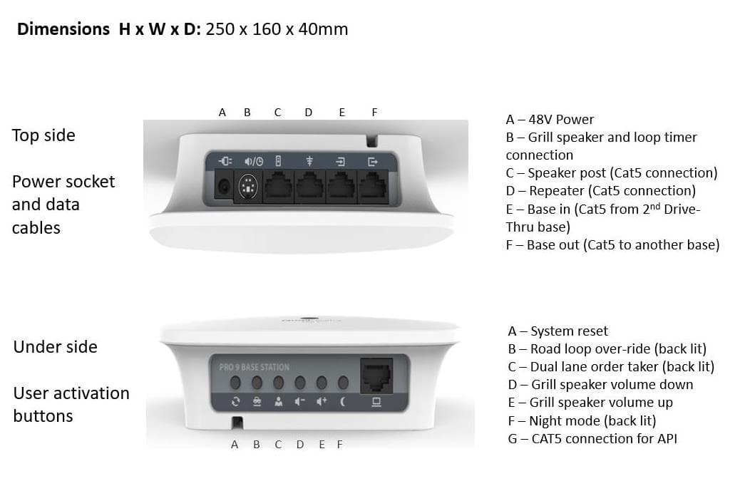
UDDQP9BS
Jan 05, 2021Quail Pro 9 Base Station
Equipment Class
PUB - Part 15 Unlicensed PCS Base Station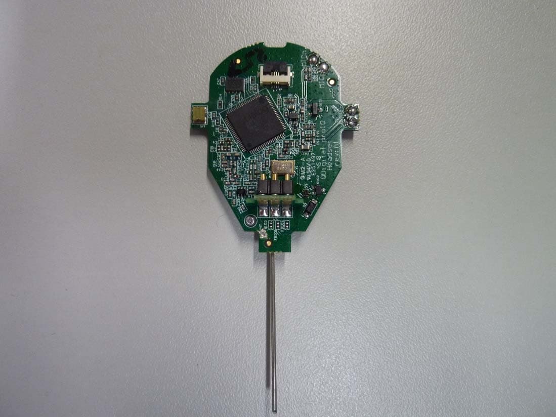
UDDQP10HS
Nov 24, 2020DECT headset
Equipment Class
PUE - Part 15 Unlicensed PCS portable Tx held to ear
UDDQP7BS
Jul 14, 2014Dect Wireless Communication
Equipment Class
PUB - Part 15 Unlicensed PCS Base Station
UDDQDTB
Jan 29, 2013Q-DTB (QD Drive Thru Base)
Equipment Class
PUB - Part 15 Unlicensed PCS Base Station
UDDQDT8
Jan 29, 2013Q-DT8 (QD Drive Thru Headset)
Equipment Class
PUE - Part 15 Unlicensed PCS portable Tx held to ear