V7TDH301Wireless N300 ADSL2+ High Power Modem Router
SHENZHEN TENDA TECHNOLOGY CO., LTD.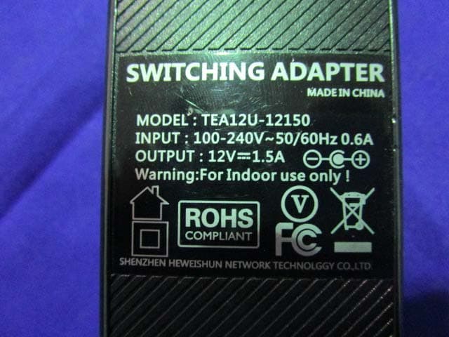
Click to zoom
Application Details
- Equipment Class
- DTS - Digital Transmission System
- Date of Grant
- Mar 04, 2015
- Application Purpose
- Original Equipment
- Date of Application
- Mar 04, 2015
- Equipment Note
- Wireless N300 ADSL2+ High Power Modem Router
- Frequency Range
- 2422.00000000 - 2452.00000000
- Country
- China
Documents & Files
Document Text
Text extracted from the exhibit documents filed with the FCC. Open a document above to read the original.
Users Manual
Wireless N300 ADSL2+ High Power Modem Router i Wireless N300 ADSL2+ High Power Modem Router ii Copyright Statement is the registered trademark of Shenzhen Tenda Technology Co., Ltd. All the products and product names mentioned herein are the trademarks or registered trademarks of their respective holders. Copyright of the whole product as integration, including its accessories and software, belongs to Shenzhen Tenda Technology Co., Ltd. No part of this publication can be reproduced, transmitted, transcribed, stored in a retrieval system, or translated into any language in any form or by any means without the prior written permission of Shenzhen Tenda Technology Co., Ltd. If you would like to know more about our product information, please visit our website at http://www.tendacn.com. Disclaimer Pictures, images and product specifications herein are for references only. To improve internal design, operational function, and/or reliability, Tenda reserves the right to make changes to the products without obligation to notify any person or organization of such revisions or changes. Tenda does not assume any liability that may occur due to the use or application of the product described herein. Every effort has been made in the preparation of this document to ensure accuracy of the contents, but all statements, information and recommendations in this document do not constitute the warranty of any kind, express or implied. Technical Support Website: http://www.tendacn.com Telephone: (86 755) 2765 7180 Email: [email protected] Wireless N300 ADSL2+ High Power Modem Router iii Contents Chapter 1 Get to Know Your Router ..................................................................................................................................... 1 1.1 What it does ............................................................................................................................................................ 1 1.2 Product Features ...................................................................................................................................................... 1 1.3 Package Contents .................................................................................................................................................... 2 Chapter 2 Hardware Install ................................................................................................................................................... 3 2.1 LED Indicators, Buttons and Interfaces .................................................................................................................. 3 2.2 Install the Device .................................................................................................................................................... 5 Chapter 3 Quick Internet Setup ............................................................................................................................................. 6 3.1 Log in to Web Manager ........................................................................................................................................... 6 3.2 Internet Setup .......................................................................................................................................................... 6 3.2.1 ADSL Mode ................................................................................................................................................. 6 3.2.2 Ethernet Mode .............................................................................................................................................. 8 3.2.3 Test Internet Connectivity ............................................................................................................................ 9 Chapter 4 Advanced Settings .............................................................................................................................................. 10 4.1 Device Info ............................................................................................................................................................ 11 4.1.1 Summary .................................................................................................................................................... 11 4.1.2 WAN........................................................................................................................................................... 12 4.1.3 Statistics ..................................................................................................................................................... 12 4.1.4 Route .......................................................................................................................................................... 14 4.1.5 ARP ............................................................................................................................................................ 14 4.1.6 DHCP ......................................................................................................................................................... 15 4.2 Advanced Setup..................................................................................................................................................... 15 4.2.1 Layer2 Interface ......................................................................................................................................... 15 4.2.2 WAN Service .............................................................................................................................................. 18 4.2.3 LAN ........................................................................................................................................................... 85 4.2.4 NAT ...............................................................................................................................................…
Text truncated - open the document above for the full version.
Users Manual
Wireless N300 ADSL2+ High Power Modem Router 117 4.2.13 Storage Service This section helps you to use USB Storage devices in your modem router, including the following parts: • User Account: You can control the LAN users’ accessing to the USB storage device information, namely, some of them can access the USB device info but others cannot. • Storage Device Info: When you plug the USB storage device into the USB interface of your modem router, the router can recognize that’s the USB storage device and then read the storage device’s information. 1) User Account Before you share your USB storage on the internet, you need to add a storage user account. And only the users on the user account list can visit the USB storage device plugged in the modem router. Thus, before you access the USB storage device, you need to set the user account information. To add a new account: ① Click Add to enter the user account configuration page. Wireless N300 ADSL2+ High Power Modem Router 118 ② Name your USB storage account. ③ Specify a password to secure your USB storage account. ④ Enter your password again for a confirmation. ⑤ Enter the volume name of the USB storage, which is displayed in the Storage Device Info page. ⑥ Click Apply/Save to save your configurations. 1) Storage Device Info Your modem router can automatically recognize the USB storage device and the Storage Device Info screen will show the information such as the volumename, file system, total space, and used space. Wireless N300 ADSL2+ High Power Modem Router 119 After your modem router recognizes the USB storage device, follow guidelines below for visiting the storage info via the computer on the LAN. Here takes Windows 7 as an example to explain the guidelines which are similar in other operation systems. ① Press Win+R keys . On the Run window, input \\192.168.1.1 (\\+ LAN IP address of the router), and then click OK. ② Double click the USB storage device icon (“mnt”). Wireless N300 ADSL2+ High Power Modem Router 120 ③ Account authentication: Enter your user account name and password which were configured in User Account part in the corresponding box, and click OK. 4.2.14 Interface Grouping Interface Grouping supports multiple ports to PVC and bridging groups. Each group will perform as an independent Wireless N300 ADSL2+ High Power Modem Router 121 network. Only the default group has IP interface. Click Advanced Setup > Interface Grouping to enter the following figure. Click Add to enter the screen below. Group Name: The name of a configured rule. WAN Interface used in the grouping: WAN connection to which the interface grouping rules apply. Available LAN Interfaces: LAN interfaces that can be used for interface grouping. Grouped LAN Interfaces: LAN interfaces that use specified WAN interface. Wireless N300 ADSL2+ High Power Modem Router 122 To create a new interface group: Enter the Group name which should be unique. Select the WAN interface that’s shared by the LAN interfaces in the interface group. Select interfaces that will be connected to the specified WAN you will use. Note that these clients may obtain public IP addresses. Click Apply/Save button to make the changes effective immediately. If you want to bypass NAT via the router’s interface and obtain the public IP address automatically, you need to add the DHCP vendor ID in the Automatically Add Clients with the following DHCP Vendor IDs section. After the ID takes effect, your router will automatically detect the DHCP request from computers on the LAN, and it will forward the DHCP vendor ID and the corresponding DHCP request to the WAN interface used in the interface rules. Application: You have established two WAN service ports: IPoE and Bridge port. Ipoe_eth0/eth1 is used for home users access; br_eth0/eht0.2 used for guests to access the Internet. You hope that eth1 and eth2 (Interface2 and 3 on the modem router) can be used for guests to visit the Internet, and meanwhile data of the guest won’t be forwarded to other interfaces. Configurations are as below in the figure. Wireless N300 ADSL2+ High Power Modem Router 123 Attention: After successful interface grouping, clients connecting to interface 2 and 3 will obtain IP address different from 192.168.1.X, but same segment with 192.168.2.1. So clients access the device via 192.168.2.1. Note 1. After the settings above, you need to reboot the modem router to take the settings into effect. 2. After the settings above, the LAN IP address used by the Default group member is 192.168.1.1, the LAN IP of the second group member is 192.168.2.1. LAN IPs of the following groups follows the same rule. 3. After you set the IPTV function, the modem router will automatically add one interface group named IPTV, which should be saved. If it’s deleted, the IPTV function takes no effect. 4.2.15 IP Tunnel This section explains the following information: • IPv6inIPv4 • IPv4inIPv6 IPv6inIPv4 Click IPv6inIPv4 and Add to enter the following screen: Wireless N300 ADSL2+ High Power Modem Router 124 Tunnel Name: Specify the name of the tunnel. Mechanism: Currently, only 6RD configuration is supported. Associated WAN Interface: Specify the WAN interface of the tunnel. Associated LAN Interface: Specify the LAN interface of the tunnel. Manual: If you select Manual, configure the following settings also: IPv4 Mask Length: Specify the IPv4 Mask Length. 6rd Prefix with Prefix Length: Specify the 6rd Prefix with Prefix Length. Border Relay IPv4 Address: Specify the Border Relay IPv4 Address. Automatic: If Automatic is selected, no configurations are required. Apply/Save: Click to apply and save your settings. IPv4inIPv6 Click IPv4inIPv6 and Add to enter the following screen: Wireless N300 ADSL2+ High Power Modem Router 125 Tunnel Name: Specify the name of the tunnel. Mechanism: Currently, only DS-Lite configuration is supported. Associated WAN Interface: Specify the WAN interface of the tunnel. Associated LAN Interface: Specify the LAN inter…
Text truncated - open the document above for the full version.
External Photos
Page 1 of 6 EXHIBIT B - EUT EXTERNAL PHOTOGRAPHS EUT – All View EUT – Top View Page 2 of 6 EUT – Bottom View EUT –Side View Page 3 of 6 EUT –Side View EUT –Side View Page 4 of 6 EUT –Side View EUT –Adapter View Page 5 of 6 EUT – Adapter Label View EUT – Antenna View Page 6 of 6 EUT – Antenna Port View
ID Label/Location Info
EXHIBIT A - FCC ID LABELING AND LOCATION FCC ID Label Proposed FCC ID Label Location The label shown shall be permanently affixed at a conspicuous location on the device and be readily visible to the user at the time purchase (Labeling requirements per 2.925) Label Here
Internal Photos
Page 1 of 3 EXHIBIT C - EUT INTERNAL PHOTOGRAPHS EUT – Uncover View EUT –Uncover View Page 2 of 3 EUT – Main Board Top View EUT –Main Board Bottom View Page 3 of 3 EUT –RF Chip View
RF Exposure Info
Bay Area Compliance Laboratories Corp. (Dongguan) Report No.: RDG150206005-00 FCC Part 15.247 Page 9 of 69 FCC §15.247 (i) & §1.1307 & §2.1091- MAXIMUM PERMISSIBLE EXPOSURE (MPE) Applicable Standard According to subpart 15.247(i) and subpart §1.1307, systems operating under the provisions of this section shall be operated in a manner that ensures that the public is not exposed to radio frequency energy level in excess of the Commission’s guidelines. Limits for Maximum Permissible Exposure (MPE) (§1.1310, §2.1091) (B) Limits for General Population/Uncontrolled Exposure Frequency Range (MHz) Electric Field Strength (V/m) Magnetic Field Strength (A/m) Power Density (mW/cm 2 ) Averaging Time (minutes) 0.3–1.34 614 1.63 *(100) 30 1.34–30 824/f 2.19/f *(180/f²) 30 30–300 27.5 0.073 0.2 30 300–1500 / / f/1500 30 1500–100,000 / / 1.0 30 f = frequency in MHz; * = Plane-wave equivalent power density; According to §1.1310 and §2.1091 RF exposure is calculated. Calculated Formulary: Predication of MPE limit at a given distance S = PG/4πR² = power density (in appropriate units, e.g. mW/cm 2 ); P = power input to the antenna (in appropriate units, e.g., mW); G = power gain of the antenna in the direction of interest relative to an isotropic radiator, the power gain factor, is normally numeric gain; R = distance to the center of radiation of the antenna (appropriate units, e.g., cm); Calculated Data: Mode Frequency (MHz) Antenna Gain Conducted Power Evaluation Distance (cm) Power Density (mW/cm 2 ) MPE Limit (mW/cm 2 ) (dBi) (numeric)(dBm)(mW) 802.11b 2462 5.0 3.16 18.3568.3920 0.014 1.0 802.11g 2412 5.0 3.16 22.59181.5520 0.036 1.0 802.11n HT20 2437 5.0 3.16 22.53179.0620 0.036 1.0 802.11n HT40 2437 5.0 3.16 21.51141.5820 0.028 1.0 Result: The device meet FCC MPE at 20 cm distance.
Test Report
Note: This test report is prepared for the customer shown above and for the device described herein. It may not be duplicated or used in part without prior written consent from Bay Area Compliance Laboratories Corp. (Dongguan). This report is valid only with a valid digital signature. The digital signature may be available only under the Adobe software above version 7.0. FCC PART 15.247 TEST REPORT For SHENZHEN TENDA TECHNOLOGY CO.,LTD. 6-8 Floor, Tower E3, No. 1001, Zhongshanyuan Road, Nanshan District, Shenzhen,China. 518052 FCC ID: V7TDH301 Report Type: Original Report Product Type: Wireless N300 ADSL2+ High Power Modem Router Test En gineer: Dean Liu Re port Number: RDG150206005-00 Re port Date: 2015-02-15 Reviewed By: Sula Huang RF En gineer Test Laboratory: Bay Area Compliance Laboratories Corp. (Dongguan) No.69 Pulongcun, Puxinhu Industrial Zone, Tangxia, Dongguan, Guangdong, China Tel: +86-769-86858888 Fax: +86-769-86858891 www.baclcorp.com.cn Bay Area Compliance Laboratories Corp. (Dongguan) Report No.: RDG150206005-00 FCC Part 15.247 Page 2 of 69 TABLE OF CONTENTS GENERAL INFORMATION ....................................................................................................................................... 4 PRODUCT DESCRIPTION FOR EQUIPMENT UNDER TEST (EUT) ..................................................................................... 4 OBJECTIVE ................................................................................................................................................................... 4 RELATED SUBMITTAL(S)/GRANT(S) ............................................................................................................................. 4 TEST METHODOLOGY .................................................................................................................................................. 4 TEST FACILITY ............................................................................................................................................................. 4 SYSTEM TEST CONFIGURATION .......................................................................................................................... 5 DESCRIPTION OF TEST CONFIGURATION ...................................................................................................................... 5 EQUIPMENT MODIFICATIONS ....................................................................................................................................... 5 EUT EXERCISE SOFTWARE .......................................................................................................................................... 6 SUPPORT EQUIPMENT LIST AND DETAILS .................................................................................................................... 6 EXTERNAL CABLE ........................................................................................................................................................ 7 BLOCK DIAGRAM OF TEST SETUP ................................................................................................................................ 7 SUMMARY OF TEST RESULTS ............................................................................................................................... 8 FCC §15.247 (i) & §1.1307 & §2.1091- MAXIMUM PERMISSIBLE EXPOSURE (MPE) ......................................... 9 APPLICABLE STANDARD .............................................................................................................................................. 9 FCC §15.203 - ANTENNA REQUIREMENT ........................................................................................................... 10 APPLICABLE STANDARD ............................................................................................................................................ 10 ANTENNA CONNECTOR CONSTRUCTION .................................................................................................................... 10 FCC §15.207 (a) – AC LINE CONDUCTED EMISSIONS ..................................................................................... 11 APPLICABLE STANDARD ............................................................................................................................................ 11 MEASUREMENT UNCERTAINTY .................................................................................................................................. 11 EUT SETUP ................................................................................................................................................................ 11 EMI TEST RECEIVER SETUP ....................................................................................................................................... 12 TEST PROCEDURE ...................................................................................................................................................... 12 CORRECTED AMPLITUDE & MARGIN CALCULATION ................................................................................................. 12 TEST EQUIPMENT LIST AND DETAILS ......................................................................................................................... 13 TEST RESULTS SUMMARY .......................................................................................................................................... 13 TEST DATA ................................................................................................................................................................ 13 FCC §15.209, §15.205 & §15.247(d) - SPURIOUS EMISSIONS ............................................................................. 16 APPLICABLE STANDARD ............................................................................................................................................ 16 MEASUREMENT UNCERTAINTY ......…
Text truncated - open the document above for the full version.
Test Setup Photos
Page 1 of 3 EXHIBIT D - TEST SETUP PHOTOGRAPHS Conducted Emission View-Front View Conducted Emission View- Side View Radiated Emission-Front View (Below 1 GHz) Radiated Emission-Rear View (Below 1 GHz) Radiated Emission-Front View (Above 1 GHz) Radiated Emission-Rear View (Above 1 GHz)
Contact Information
Applicant
Shen Yue(Engineer)
Test Firm
Bay Area Compliance Laboratories Corp. (Dongguan)John Chan
[email protected]86-769-86858888
Technical Specifications
| # | Rule Parts | Frequency Range | Power Output |
|---|---|---|---|
| 2 | 15C | 2.42 GHz - 2.45 GHz | 142.00 mW |
Other Applications from SHENZHEN TENDA TECHNOLOGY CO., LTD.
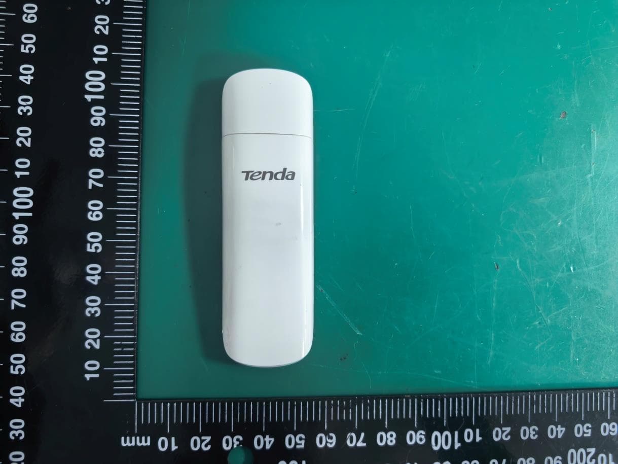
V7TU18V3
Aug 26, 2026AX1800 Wi-Fi 6 Dual-Band USB Adapter
Equipment Class
NII - Unlicensed National Information Infrastructure TX
V7TA33V2
Aug 25, 2026AX3000 Dual-Band Gigabit Wi-Fi Range Extender, AX1800 Dual-Band Gigabit Wi-Fi Range Extender
Equipment Class
DTS - Digital Transmission System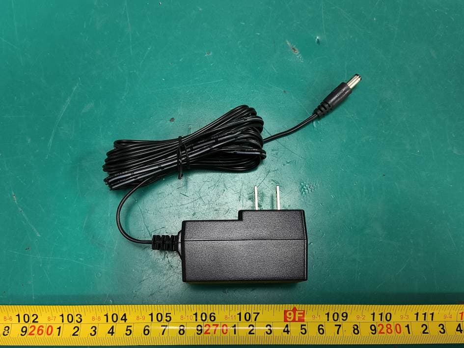
V7TCH9V2
Jul 20, 20266MP Dual-lens Linkage Wi-Fi Pan/Tilt Camera
Equipment Class
DTS - Digital Transmission System
V7TCH3V21
Jul 14, 20263MP Wi-Fi Pan/Tilt Camera
Equipment Class
DTS - Digital Transmission System
V7TCP3P1
Jun 30, 20263MP Security Pan/Tilt Camera
Equipment Class
DTS - Digital Transmission System