V7TW330AWireless N300 Ceiling Access Point
SHENZHEN TENDA TECHNOLOGY CO., LTD.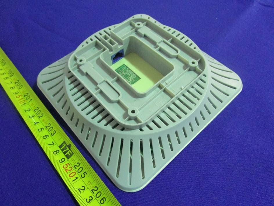
Click to zoom
Application Details
- Equipment Class
- DTS - Digital Transmission System
- Date of Grant
- Oct 16, 2014
- Application Purpose
- Original Equipment
- Date of Application
- Oct 16, 2014
- Equipment Note
- Wireless N300 Ceiling Access Point
- Frequency Range
- 2412.00000000 - 2462.00000000
- Country
- China
Documents & Files
Document Text
Text extracted from the exhibit documents filed with the FCC. Open a document above to read the original.
Users Manual
Install Guide 1 Open the Package z Wireless N300 Ceiling Access Point*1 z Ethernet Cable*1 z Bracket*1 z Screw*4 z Expansion Bolt*4 z Position Paster*1 z Install Guide*1 If any item is incorrect, missing, or damaged, please contact your reseller for immediate replacement. 2 Get to Know the Device LED Light Status Description SYS Solid The device is starting. Blinking The device is functioning normally. Off The device is receiving no electric power or the LED light is turned off on the web page of the AC. Button & Interface Function Description LAN A10/100M auto-negotiationRJ-45port that can: a) connect to a PoE device for both data and electric power transmission; b) connectto a PC, switch or any other Ethernet device for data communication only. RST Press and hold it with a needle for 6 seconds. The device will be restored to factory default settings in 1 minute. 3 Install the Device Step 1Prepare the following: Step 2Adhere the position paster onto the ceiling where your AP will be installed. Step 3Borefour 25~30mm deep holes by using the hammer drill (6mm drill bit)according to the marks on the position paster. Step 4Strike the expansion bolts into the holes with the rubber hammer, and then fix the bracket with the provided screws. Step 5Attach the device to the bracket and make sure it is aligned correctly. 4 Connect the Device Step 1Connect the AP’s LAN port to an IEEE 802.3af-compliant PoE switch’s PoE port with an Ethernet cable. Step 2 Connect an access controller to the core switch with an Ethernet cable. Step 3 Connect other devices and check the network topology. Tips z As AC500 will configure the AP,there is no need to configure the AP. If you want to know the configuration method, please refer to the user guide of AC500. z When used alone (without being managed by an access controller), this AP’s default SSID is Tenda_XXXXXX,where XXXXXX is the last six characters of its MAC addresson the label on the back of AP. ©2014 Shenzhen Tenda Technology Co., Ltd. All rights reserved. This documentation (including pictures, images, and product specifications, etc.) is for reference only. To improve internal design, operational function, and/or reliability,Tenda reserves the right to make changes to the products described in this document without obligation to notify any person or organization of such revisions or changes. 5 S CE Thi s inte dev NO T una inte FC C This two mu s ope Thi s dev rea s equ and co m part telev use — R — I Safety a Mark Warn s is a Class rference, in ice complie s TE: (1) The uthorized m rference, it i C Statemen s device com conditions: st accept an ration. s equipment ice, pursuan sonable pro ipment gene used in ac mmunications ticular insta vision recep r is encoura Reorient or Increase the and Emi ing s B product which case s with EU 19 manufacture modifications s recommen t mplies with P (1) This de ny interferen t has been t nt to Part 1 otection aga erates, uses ccordance w s. However llation. If th ption, which aged to try to relocate the e separation ission S t. In a dom e the user m 999/5/EC. er is not res s to this e nded to use Part 15 of th evice may n nce received tested and f 15 of the F ainst harmf s and can r with the inst r, there is n his equipme can be det o correct the e receiving a between t h Stateme mestic enviro may be requ ponsible for equipment. a shielded he FCC Rule not cause ha d, including found to com FCC Rules. ul interfere n adiate radio ructions, ma no guarante ent does ca termined by e interferenc ntenna. he equipmen ent onment, this uired to take any radio o (2) To av RJ45 cable. es. Operatio armful interf interference mply with the These limit nce in a re o frequency ay cause ha e that interf ause harmf y turning the e by one of nt and receiv s product m e adequate or TV interfer void unnece . on is subject ference, and e that may c e limits for a ts are desig esidential in energy and armful interf rference will ful interferen e equipment the following ver. may cause r measures. rence cause essary radia t to the follow d (2) this de cause undes a Class B d gned to pro nstallation. d, if not insta ference to r l not occur nce to radi t off and on g measures radio This ed by ation wing evice sired igital ovide This alled radio in a o or , the s: — Connect the equipment into an outlet on a circuit different from that to which the receiver is connected. — Consult the dealer or an experienced radio/TV technician for help. FCC Caution: Any changes or modifications not expressly approved by the party responsible for compliance could void the user's authority to operate this equipment. This transmitter must not be co-located or operating in conjunction with any other antenna or transmitter. The manufacturer is not responsible for any radio or TV interference caused by unauthorized modifications to this equipment. Radiation Exposure Statement This equipment complies with FCC radiation exposure limits set forth for an uncontrolled environment. This equipment should be installed and operated with minimum distance 20cm between the radiator & your body. NOTE: (1) The manufacturer is not responsible for any radio or TV interference caused by unauthorized modifications to this equipment. (2) To avoid unnecessary radiation interference, it is recommended to use a shielded RJ45 cable.
Cover Letter(s)
Engineer
External Photos
EXHIBIT B - EUT EXTERNAL PHOTOGRAPHS EUT – Top View EUT – Bottom View EUT –Side View EUT – Side View
ID Label/Location Info
EXHIBIT A - FCC ID LABELING AND LOCATION FCC ID Label Proposed FCC ID Label Location The label shown shall be permanently affixed at a conspicuous location on the device and be readily visible to the user at the time purchase (Labeling requirements per 2.925) Label Here
Internal Photos
EXHIBIT C - EUT INTERNAL PHOTOGRAPHS EUT – Uncover View EUT – Uncover View EUT – Uncover View EUT – Main Board Top View EUT –Main Board Bottom View EUT –Antenna View EUT –RF Chip View
RF Exposure Info
Bay Area Compliance Laboratories Corp. (Dongguan) Report No.: RDG140918003-00 FCC Part 15.247 Page 8 of 72 FCC §15.247 (i) & §1.1310 & §2.1091- MAXIMUM PERMISSIBLE EXPOSURE (MPE) Applicable Standard According to subpart 15.247(i)and subpart §1.1310, systems operating under the provisions of this section shall be operated in a manner that ensures that the public is not exposed to radio frequency energy level in excess of the Commission’s guidelines. Limits for Maximum Permissible Exposure (MPE) (§1.1310, §2.1091) (B) Limits for General Population/Uncontrolled Exposure Frequency Range (MHz) Electric Field Strength (V/m) Magnetic Field Strength (A/m) Power Density (mW/cm 2 ) Averaging Time (minutes) 0.3–1.34 614 1.63 *(100) 30 1.34–30 824/f 2.19/f *(180/f²) 30 30–300 27.5 0.073 0.2 30 300–1500 / / f/1500 30 1500–100,000 / / 1.0 30 f = frequency in MHz; * = Plane-wave equivalent power density; According to §1.1310 and §2.1091 RF exposure is calculated. Calculated Formulary: Predication of MPE limit at a given distance S = PG/4πR² = power density (in appropriate units, e.g. mW/cm 2 ); P = power input to the antenna (in appropriate units, e.g., mW); G = power gain of the antenna in the direction of interest relative to an isotropic radiator, the power gain factor, is normally numeric gain; R = distance to the center of radiation of the antenna (appropriate units, e.g., cm); Calculated Data: Mode Frequency (MHz) Antenna Gain Conducted Power Evaluation Distance (cm) Power Density (mW/cm 2 ) MPE Limit (mW/cm 2 ) (dBi) (numeric)(dBm)(mW) 802.11b 2462 3.5 2.24 21.82152.05 20.00 0.06776 1.0 802.11g 2437 3.5 2.24 23.37217.27 20.00 0.09682 1.0 802.11n HT20 2462 3.5 2.24 24.92310.46 20.00 0.13834 1.0 802.11n HT40 2452 3.5 2.24 24.21263.63 20.00 0.11748 1.0 Result: The device meet FCC MPE at 20 cm distance
Test Report
Note: This test report is prepared for the customer shown above and for the device described herein. It may not be duplicated or used in part without prior written consent from Bay Area Compliance Laboratories Corp. (Dongguan). This report is valid only with a valid digital signature. The digital signature may be available only under the Adobe software above version 7.0. FCC PART 15.247 TEST REPORT For SHENZHEN TENDA TECHNOLOGY CO.,LTD. 6-8 Floor, Tower E3, No. 1001, Zhongshanyuan Road, Nanshan District, Shenzhen,China. 518052 FCC ID: V7TW330A Report Type: Original Report Product Type: Wireless N300 Ceiling Access Point Test En gineer: Dean Liu Re port Number: RDG140918003-00 Re port Date: 2014-09-30 Reviewed By: Sula Huang EMC En gineer Test Laboratory: Bay Area Compliance Laboratories Corp. (Dongguan) No.69 Pulongcun, Puxinhu Industrial Zone, Tangxia, Dongguan, Guangdong, China Tel: +86-769-86858888 Fax: +86-769-86858891 www.baclcorp.com.cn Bay Area Compliance Laboratories Corp. (Dongguan) Report No.: RDG140918003-00 FCC Part 15.247 Page 2 of 72 TABLE OF CONTENTS GENERAL INFORMATION ....................................................................................................................................... 4 PRODUCT DESCRIPTION FOR EQUIPMENT UNDER TEST (EUT) ..................................................................................... 4 OBJECTIVE ................................................................................................................................................................... 4 RELATED SUBMITTAL(S)/GRANT(S) ............................................................................................................................. 4 TEST METHODOLOGY .................................................................................................................................................. 4 TEST FACILITY ............................................................................................................................................................. 4 SYSTEM TEST CONFIGURATION .......................................................................................................................... 5 DESCRIPTION OF TEST CONFIGURATION ...................................................................................................................... 5 EQUIPMENT MODIFICATIONS ....................................................................................................................................... 5 EUT EXERCISE SOFTWARE .......................................................................................................................................... 5 SUPPORT EQUIPMENT LIST AND DETAILS .................................................................................................................... 5 EXTERNAL CABLE ........................................................................................................................................................ 6 BLOCK DIAGRAM OF TEST SETUP ................................................................................................................................ 6 SUMMARY OF TEST RESULTS ............................................................................................................................... 7 FCC §15.247 (i) & §1.1310 & §2.1091- MAXIMUM PERMISSIBLE EXPOSURE (MPE) ......................................... 8 APPLICABLE STANDARD .............................................................................................................................................. 8 FCC §15.203 - ANTENNA REQUIREMENT ............................................................................................................. 9 APPLICABLE STANDARD .............................................................................................................................................. 9 ANTENNA CONNECTOR CONSTRUCTION ...................................................................................................................... 9 FCC §15.207 (a) – AC LINE CONDUCTED EMISSIONS ..................................................................................... 10 APPLICABLE STANDARD ............................................................................................................................................ 10 MEASUREMENT UNCERTAINTY .................................................................................................................................. 10 EUT SETUP ................................................................................................................................................................ 10 EMI TEST RECEIVER SETUP ....................................................................................................................................... 11 TEST PROCEDURE ...................................................................................................................................................... 11 CORRECTED AMPLITUDE & MARGIN CALCULATION ................................................................................................. 11 TEST EQUIPMENT LIST AND DETAILS ......................................................................................................................... 12 TEST RESULTS SUMMARY .......................................................................................................................................... 12 TEST DATA ................................................................................................................................................................ 12 FCC §15.209, §15.205 & §15.247(d) - SPURIOUS EMISSIONS ............................................................................. 15 APPLICABLE STANDARD ............................................................................................................................................ 15 MEASUREMENT UNCERTAINTY ............…
Text truncated - open the document above for the full version.
Test Setup Photos
EXHIBIT D - TEST SETUP PHOTOGRAPHS Conducted Emissions - Front View Conducted Emissions – Side View Radiated Emission Below 1GHz –Front View Radiated Emission Below 1GHz –Rear View Radiated Emission Above 1GHz –Front View Radiated Emission Above 1GHz –Rear View
Contact Information
Applicant
Shen Yue(Engineer)
Test Firm
Bay Area Compliance Laboratories Corp. (Dongguan)John Chan
[email protected]86-769-86858888
Technical Specifications
| # | Rule Parts | Frequency Range | Power Output |
|---|---|---|---|
| 1 | 15C | 2.41 GHz - 2.46 GHz | 310.00 mW |
Other Applications from SHENZHEN TENDA TECHNOLOGY CO., LTD.
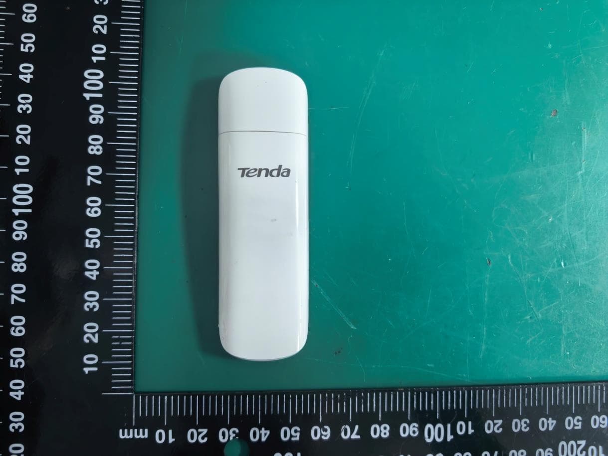
V7TU18V3
Aug 26, 2026AX1800 Wi-Fi 6 Dual-Band USB Adapter
Equipment Class
NII - Unlicensed National Information Infrastructure TX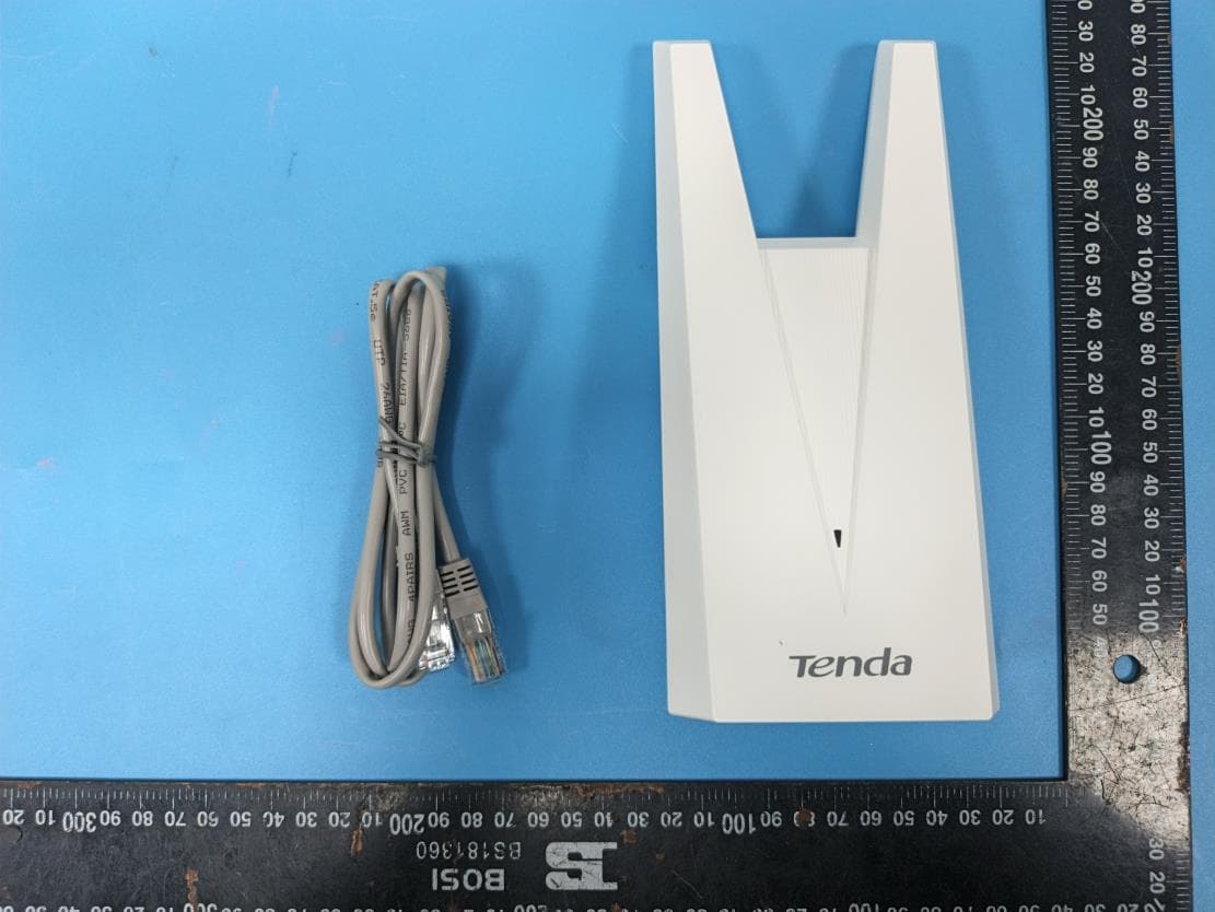
V7TA33V2
Aug 25, 2026AX3000 Dual-Band Gigabit Wi-Fi Range Extender, AX1800 Dual-Band Gigabit Wi-Fi Range Extender
Equipment Class
DTS - Digital Transmission System
V7TCH9V2
Jul 20, 20266MP Dual-lens Linkage Wi-Fi Pan/Tilt Camera
Equipment Class
DTS - Digital Transmission System
V7TCH3V21
Jul 14, 20263MP Wi-Fi Pan/Tilt Camera
Equipment Class
DTS - Digital Transmission System
V7TCP3P1
Jun 30, 20263MP Security Pan/Tilt Camera
Equipment Class
DTS - Digital Transmission System