VIYARC0540Bluetooth module
Hosiden Corporation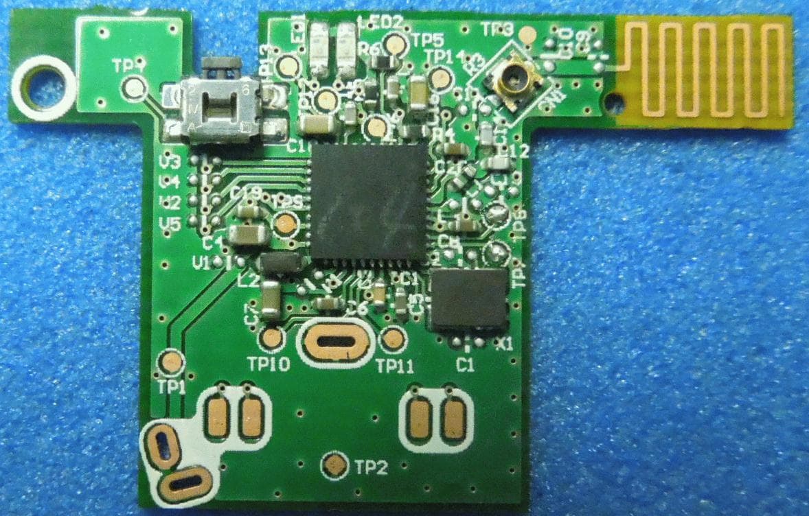
Click to zoom
Application Details
- Equipment Class
- DSS - Part 15 Spread Spectrum Transmitter
- Date of Grant
- Oct 21, 2013
- Application Purpose
- Original Equipment
- Date of Application
- Oct 21, 2013
- Equipment Note
- Bluetooth module
- Frequency Range
- 2402.00000000 - 2480.00000000
- Company
- Hosiden Corporation
- Country
- Japan
Documents & Files
Document Text
Text extracted from the exhibit documents filed with the FCC. Open a document above to read the original.
Users Manual
Product: Bluetooth module Model: ARC0540 For OEM integration only – device cannot be sold to general public. Therefore we will not supply the User’s manual, the installation manual is the official for OEM. FCC ID: VIYARC0540 IC: 409B-ARC0540 We will ask OEM to include the following Notices required by FCC/IC on the product and in the User’s manual. ■ Requirement of Labeling Please describe the following item on the host device of this module: Contains FCC ID: VIYARC0540 Contains IC: 409B-ARC0540 FCC/INDUSTRY CANADA NOTICE This device complies with Part 15 of FCC Rules and Industry Canada license-exempt RSS standard(s). Operation is subject to the following two conditions: (1) this device may not cause interference, and (2) this device must accept any interference, including interference that may cause undesired operation of this device. Note: This equipment has been tested and found to comply with the limits for a Class B digital device, pursuant to part 15 of the FCC Rules. These limits are designed to provide reasonable protection against harmful interference in a residential installation. This equipment generates, uses and can radiate radio frequency energy and, if not installed and used in accordance with the instructions, may cause harmful interference to radio communications. However, there is no guarantee that interference will not occur in a particular installation. If this equipment does cause harmful interference to radio or television reception, which can be determined by turning the equipment off and on, the user is encouraged to try to correct the interference by one or more of the following measures: —Reorient or relocate the receiving antenna. —Increase the separation between the equipment and receiver. —Connect the equipment into an outlet on a circuit different from that to which the receiver is connected. —Consult the dealer or an experienced radio/TV technician for help. Note: This transmitter must not be co-located or operated in onjunction with any other antenna or transmitter. FCC CAUTION Changes or modifications not expressly approved by Hosiden Corporation responsible for compliance could void the user’s authority to operate the equipment. Note: FCC/INDUSTRY CANADA Radiation Exposure Statement: This equipment complies with FCC/IC radiation exposure limits set forth for an uncontrolled environment and meets the FCC radio frequency (RF) Exposure Guidelines and RSS-102 of the IC radio frequency (RF) Exposure rules. This equipment has very low levels of RF energy that are deemed to comply without testing of specific absorption ratio (SAR). Le présent appareil est conforme aux la partie 15 des règles de la FCC et CNR d'Industrie Canada applicables aux appareils radio exempts de licence. L'exploitation est autorisée aux deux conditions suivantes : (1) l'appareil ne doit pas produire de brouillage, et (2) l'utilisateur de l'appareil doit accepter tout brouillage radioélectrique subi, même si le brouillage est susceptible d'en compromettre le fonctionnement. Cet équipement est conforme aux limites d’exposition aux rayonnements énoncées pour un environnement non contrôlé et respecte les règles les radioélectriques (RF) de la FCC lignes directrices d'exposition et d’exposition aux fréquences radioélectriques (RF) CNR-102 de l’IC. Cet équipement émet une énergie RF très faible qui est considérée conforme sans évaluation du débit d’absorption spécifique (DAS).
External Photos
Photographs of ARC0540 <Top side of PCB> <Back side of PCB>
ID Label/Location Info
Label information Location of label Following IDs are displayed inside of red square area (backside of PWB) with silk printing. Detail of label Model: ARC0540 FCC ID: VIYARC0540 IC ID: 409B-ARC0540
Internal Photos
Photographs of ARC0540 <Top side of PCB> <Back side of PCB>
Test Report
Test report No. : 10037307H-B Page : 2 of 33 Issued date : September 11, 2013 FCC ID : VIYARC0540 UL Japan, Inc. Head Office EMC Lab. 4383-326 Asama-cho, Ise-shi, Mie-ken 516-0021 JAPAN Telephone : +81 596 24 8999 Facsimile : +81 596 24 8124 REVISION HISTORY Original Test Report No.: 10037307H-B Revision Test report No. Date Page revised Contents - (Original) 10037307H-B September 11, 2013 - - Test report No. : 10037307H-B Page : 3 of 33 Issued date : September 11, 2013 FCC ID : VIYARC0540 UL Japan, Inc. Head Office EMC Lab. 4383-326 Asama-cho, Ise-shi, Mie-ken 516-0021 JAPAN Telephone : +81 596 24 8999 Facsimile : +81 596 24 8124 CONTENTS PAGE SECTION 1: Customer information ......................................................................................................... 4 SECTION 2: Equipment under test (E.U.T.) ........................................................................................... 4 SECTION 3: Test specification, procedures & results ............................................................................ 5 SECTION 4: Operation of E.U.T. during testing .................................................................................... 8 SECTION 5: Radiated Spurious Emission ............................................................................................ 10 SECTION 6: Antenna Terminal Conducted Tests ................................................................................ 11 APPENDIX 1: Data of EMI test .............................................................................................................. 12 20dB Bandwidth and Carrier Frequency Separation ......................................................................... 12 Number of Hopping Frequency ........................................................................................................ 14 Dwell time ......................................................................................................................................... 16 Maximum Peak Output Power .......................................................................................................... 18 Radiated Spurious Emission ............................................................................................................. 19 Conducted Spurious Emission .......................................................................................................... 22 Conducted Emission Band Edge compliance ................................................................................... 28 99%Occupied Bandwidth ................................................................................................................. 29 APPENDIX 2: Test instruments ............................................................................................................. 31 APPENDIX 3: Photographs of test setup ............................................................................................... 32 Radiated Spurious Emission ............................................................................................................. 32 Worst Case Position (Horizontal: Y-axis/ Vertical:Z-axis) .............................................................. 33 Test report No. : 10037307H-B Page : 4 of 33 Issued date : September 11, 2013 FCC ID : VIYARC0540 UL Japan, Inc. Head Office EMC Lab. 4383-326 Asama-cho, Ise-shi, Mie-ken 516-0021 JAPAN Telephone : +81 596 24 8999 Facsimile : +81 596 24 8124 SECTION 1: Customer information Company Name : Hosiden Corporation Address : 1-4-33, Kitakyuhoji, Yao, Osaka, 5810071, Japan Telephone Number : +81-72-924-1195 Facsimile Number : +81-72-993-0724 Contact Person : Keiji Mine SECTION 2: Equipment under test (E.U.T.) 2.1 Identification of E.U.T. Type of Equipment : Bluetooth module Model No. : ARC0540 Serial No. : Refer to Section 4, Clause 4.2 Rating : DC 2.0 to DC 3.0V Receipt Date of Sample : August 4, 2013 Country of Mass-production : China Condition of EUT : Production prototype (Not for Sale: This sample is equivalent to mass-produced items.) Modification of EUT : No Modification by the test lab 2.2 Product Description General Specification Clock frequency(ies) in the system : 16MHz Radio Specification [Bluetooth (Ver. 3.0 without EDR function)] Radio Type : Transceiver Frequency of Operation : 2402-2480MHz Modulation : FHSS, GFSK Power Supply (radio part input) : DC 1.8V Antenna type : PWB pattern antenna Antenna Gain : -3dBi Test report No. : 10037307H-B Page : 5 of 33 Issued date : September 11, 2013 FCC ID : VIYARC0540 UL Japan, Inc. Head Office EMC Lab. 4383-326 Asama-cho, Ise-shi, Mie-ken 516-0021 JAPAN Telephone : +81 596 24 8999 Facsimile : +81 596 24 8124 SECTION 3: Test specification, procedures & results 3.1 Test Specification Test Specification : FCC Part 15 Subpart C: 2013, final revised on June 11, 2013 and effective July 11, 2013 Title : FCC 47CFR Part15 Radio Frequency Device Subpart C Intentional Radiators Section 15.207 Conducted limits Section 15.247 Operation within the bands 902-928MHz, 2400-2483.5MHz, and 5725-5850MHz * The EUT complies with FCC Part 15 Subpart B: 2013, final revised on June 11, 2013 and effective July 11, 2013. 3.2 Procedures and results Item Test Procedure Specification Worst Margin Results Remarks Conducted Emission FCC: ANSI C63.4:2003 7. AC powerline conducted emission measurements FCC: Section 15.207 N/A *1) N/A - IC: RSS-Gen 7.2.4 IC: RSS-Gen 7.2.4 Carrier Frequency Separation FCC: FCC Public Notice DA 00-705 FCC: Section15.247(a)(1) See data. Complied Conducted IC: - IC: RSS-210 A8.1 (b) 20dB Bandwidth FCC: FCC Public Notice DA 00-705 FCC: Section15.247(a)(1) Complied Conducted IC: - IC: RSS-210 A8.1 (a) Number of Hopping Frequency FCC: FCC Public Notice DA 00-705 FCC: Section15.247(a)(1)(iii) Complied Conducted IC: - IC: RSS-210 A8.1 (d) Dwell time FCC: FCC Public Notice DA 00-705 FCC: Section15.247(a)(1)(iii) Complied Conducted IC: - IC: RSS-210 A8.1 (d) Maximum Peak Output Power …
Text truncated - open the document above for the full version.
Test Setup Photos
Test report No. : 10037307H-B Page : 32 of 33 Issued date : September 11, 2013 FCC ID : VIYARC0540 UL Japan, Inc. Head Office EMC Lab. 4383-326 Asama-cho, Ise-shi, Mie-ken 516-0021 JAPAN Telephone : +81 596 24 8999 Facsimile : +81 596 24 8124 APPENDIX 3: Photographs of test setup Radiated Spurious Emission Photo 1 Photo 2 Test report No. : 10037307H-B Page : 33 of 33 Issued date : September 11, 2013 FCC ID : VIYARC0540 UL Japan, Inc. Head Office EMC Lab. 4383-326 Asama-cho, Ise-shi, Mie-ken 516-0021 JAPAN Telephone : +81 596 24 8999 Facsimile : +81 596 24 8124 Worst Case Position (Horizontal: Y-axis/ Vertical:Z-axis) X-axis Y-axis Z-axis End of Report
Contact Information
Applicant
Yasuo Nakai(Executive officers, chief of headquarters)
Technical Contact
UL Japan, Inc.Takahiro Hatakeda
[email protected]81-596-24-8116
4383-326 Asama-cho, Ise-shi · Mie-ken · Japan
Test Firm
UL Japan, Inc. Head office EMC Lab.Tetsuya Hashimoto
Technical Specifications
| # | Rule Parts | Frequency Range | Power Output |
|---|---|---|---|
| 1 | 15C | 2.40 GHz - 2.48 GHz | 1.50 mW |
Other Applications from Hosiden Corporation
VIYCBC4077
Jun 08, 2024CRADLE ASSY, MOBILE WIRELESS CHARGER
Equipment Class
8CC - Part 18 Consumer Device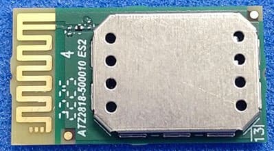
VIYHRM1086
Nov 07, 2022Bluetooth Dual Module
Equipment Class
DTS - Digital Transmission System
VIYHRM3012
Mar 14, 2020Bluetooth Low Energy Module
Equipment Class
DTS - Digital Transmission System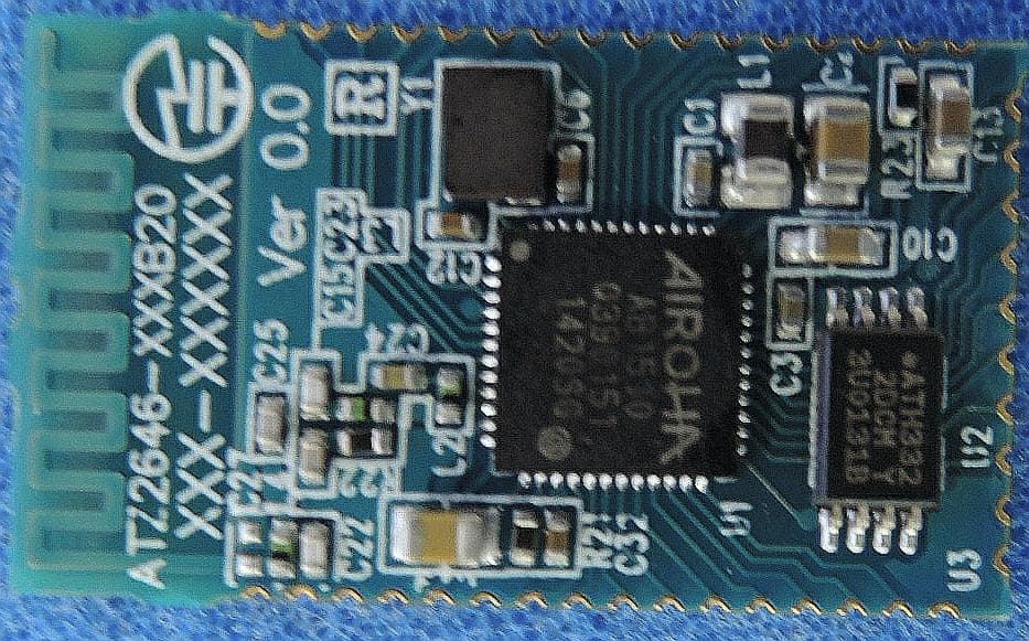
VIYHRM1034
Nov 09, 2014Bluetooth module
Equipment Class
DSS - Part 15 Spread Spectrum Transmitter
VIYHRM1026A
May 01, 2014Wireless Low Energy Module
Equipment Class
DTS - Digital Transmission System