VOB-P2571Complex Set-Top Box
NVIDIA Corporation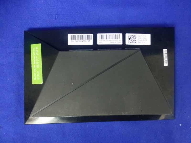
Click to zoom
Application Details
- Equipment Class
- DTS - Digital Transmission System
- Date of Grant
- Mar 11, 2015
- Application Purpose
- Original Equipment
- Date of Application
- Mar 10, 2015
- Equipment Note
- Complex Set-Top Box
- Frequency Range
- 2422.00000000 - 2452.00000000
- Company
- NVIDIA Corporation
- Country
- United States
Documents & Files
Document Text
Text extracted from the exhibit documents filed with the FCC. Open a document above to read the original.
Users Manual
ABOUT SHIELD SHIELD tech specs Chipset 1.9GHz 64-bit Quad Core, NVIDIA® Tegra® K1 CPU 256 Core Maxwell GPU Memory 3GB RAM 16GB or 500GB storage* Ports 40W DC power Gigabit Ethernet HDMI out (4K x 2K @ 60Hz) Micro-USB 2.0 Two USB 3.0 (Type A) MicroSD storage slot IR Receiver (compatible with Logitech Harmony) Connectivity 802.11ac 2x2 (MIMO) Bluetooth 4.1 Size 130mm x 210mm x 25mm Game Controller Wi-Fi Direct wireless connectivity Built-in stereo headphone jack and microphone Micro-USB 2.0 for charging or wired gameplay 3.5 mm stereo headphone jack with voice chat support *Actual local storage may be less. SHIELD Hardware Here's a guide to the hardware features of the SHIELD. SHIELD Front 1. Indicator light 2. On/Off button (capacitive touch) Back Ports from right to left: 1. Power port 2. HDMI 2.0 port 3. Gigabit Ethernet port 4. USB 3.0 port 5. USB 3.0 port 6. Micro USB 2.0 port 7. MicroSD card slot SHIELD Controller 1. D-pad 2. NVIDIA button 3. Android navigation and Start buttons 4. A B X Y buttons 5. Left thumbstick 6. Right thumbstick 7. Touchpad 8. Volume control What comes with SHIELD SHIELD comes with the following: • SHIELD • SHIELD controller • HDMI cable • Power adapter (including plugs for North America, UL, and rest of Europe) • USB cable A Quick Start guide and Warranty, Safety and Regulatory booklet are also included. GET STARTED WITH SHIELD What you need Here’s what you’ll need to start using your SHIELD: 1. TV or monitor with HDMI port* 2. HDMI cable with male Type A connector on each end 3. Internet connection via Wi-Fi 4. A Google account *Note: HDCP compatible HDMI port is required. Set up SHIELD and pair remote Here’s how to plug in your SHIELD and set up your remote. 1. Connect your SHIELD to your TV with the HDMI cable • Make sure your TV or monitor is turned off. 2. Connect your SHIELD to power, using the power cord • Plug one end of the power cable into the back of your SHIELD, and the other into a power outlet. • Touch the SHIELD power button (NVIDIA logo) on the top of your SHIELD. You’ll see the light on your SHIELD console turn on. • Keep in mind, once you start using your SHIELD, it won’t need to be turned off. When you’re not using it, it will automatically go into sleep mode. 3. Turn on your SHIELD controller • Tap the NVIDIA button on the controller 4. Turn on your TV and press the source or input button until you see the Welcome screen • If the controller is on (NVIDIA button will be flashing) the controller will pair with SHIELD. • The Welcome screen will appear when you’ve selected the correct HDMI port and successfully paired your controller. • If you have trouble finding the correct input, check if the HDMI ports on your TV or monitor are labeled. • If the controller does not pair, hold the NVIDIA button until the button starts flashing and then let go. Your device and controller setup is complete. Next, you’ll follow the on-screen setup. On-screen setup for SHIELD Before you start setting up your SHIELD, make sure of the following: • You have a reliable Wi-Fi network you can connect to. • Your controller is paired with your SHIELD. To set up SHIELD console, just follow the on-screen instructions. You'll be prompted to do the following: • Choose your language • Choose and join your Wi-Fi network. • If your SHIELD needs a software update, it'll automatically install it and then restart. • Sign in with your Google account. You have a couple options: o "Use your password": enter your email and password using your remote. o "Use your phone or laptop": Instead of entering your email and password with your remote, you can use a browser on your phone or laptop to sign in. Make sure your phone or laptop is on the same Wi-Fi network as your SHIELD console. Go to g.co/AndroidTV and enter the PIN you see on your TV screen. This feature is not available in every country. Tip: Once you connect to Wi-Fi, you can start using your phone or tablet as a remote. This allows you to use your phone or tablet’s keyboard. That's it! Learn what you can do with your Android TV. Using your SHIELD remote Use your SHIELD controller to navigate the screen. Use the controller’s D-pad to move up, down, left and right. To select an item, press “A”. A full controller guide can be found here: http://shield.nvidia.com/controller-user-guide Your SHIELD controller doesn’t control your TV volume or input. Use the remote that came with your TV. Using the Android TV Remote Control app You need an Android phone or tablet running Android 4.3 or higher to use the Android TV Remote Control app. You can control your TV through your phone or tablet with the Android TV Remote Control app. Set up the remote control app 1. Download and install the Android TV Remote Control app on your phone or tablet. You can also search for “Android TV Remote Control” on Google Play. 2. Make sure your phone or tablet is on the same Wi-Fi network as your Android TV. 3. Open the Android TV Remote Control app on your phone or tablet. 4. In the app, you’ll see your Android TV listed. Touch the name. 5. On your TV screen, you’ll see a PIN. Enter this PIN on your phone or tablet. 6. Then touch Pair. Use the remote control app You can use the Android TV Remote Control app to navigate your TV screen. Search You can also use your remote to search with your voice, by touching the Voice Search button . Keyboard If you need to type on your Android TV, touch the keyboard at the top of the app to bring up a keyboard. The keyboard may not be supported on all apps. Remote layout You can choose from two layouts for your remote: 1. Standard remote layout (D-pad) o Touch arrows to move up, down, right, and left on your TV o Touch the center circle to select 2. Trackpad remote o Swipe your mobile device’s screen up, down, left or right to navigate on your TV o Touch anywhere on the screen to select EXPLORE ANDROID TV Browse the Android TV Home screen From the Android TV home screen, you can easily access movies, TV shows, music, apps,…
Text truncated - open the document above for the full version.
External Photos
R AUDIX Technology (Shenzhen) Co., Ltd. IC:7361A-P2571 page Audix Technology (Shenzhen) Co., Ltd. Report No. ACS-I15001 13-1 13. PHOTOGRAPH OF EUT Figure 1 General Appearance of the EUT Figure 2 General Appearance of the EUT R AUDIX Technology (Shenzhen) Co., Ltd. IC:7361A-P2571 page Audix Technology (Shenzhen) Co., Ltd. Report No. ACS-I15001 13-2 Figure 3 General Appearance of the EUT Figure 4 General Appearance of the EUT
ID Label/Location Info
NOTICE OF PROPRIETARY PROPERTY. THE INFORMATION CONTAINED HEREIN IS THE PROPRIETARY PROPERTY OF NVIDIA CORP. THE POSSESSOR AGREES TO THE FOLLOWING: (i) TO MAINTAIN THIS DOCUMENT IN CONFIDENCE,(ii) NOT TO REPRODUCE OR COPY IT (iii) NOT TO REVEAL OR PUBLISH IT IN WHOLE OR PART. Model: P2571 FCC ID: VOB-P2571 IC ID: 7361A-P2571 Label: Label Location: On the rear (back) side of the device. NVIDIA Proprietary and Confidential
Internal Photos
R AUDIX Technology (Shenzhen) Co., Ltd. IC:7361A-P2571 page Audix Technology (Shenzhen) Co., Ltd. Report No. ACS-I15001 13-3 Figure 5 General Appearance of the EUT Figure 6 Inside of the EUT R AUDIX Technology (Shenzhen) Co., Ltd. IC:7361A-P2571 page Audix Technology (Shenzhen) Co., Ltd. Report No. ACS-I15001 13-4 Figure 7 Inside of the EUT Figure 8 Inside of the EUT R AUDIX Technology (Shenzhen) Co., Ltd. IC:7361A-P2571 page Audix Technology (Shenzhen) Co., Ltd. Report No. ACS-I15001 13-5 Figure 9 HDD of the EUT Figure 10 HDD of the EUT R AUDIX Technology (Shenzhen) Co., Ltd. IC:7361A-P2571 page Audix Technology (Shenzhen) Co., Ltd. Report No. ACS-I15001 13-6 Figure 11 Backside of the EUT Figure 12 Front Side of the EUT R AUDIX Technology (Shenzhen) Co., Ltd. IC:7361A-P2571 page Audix Technology (Shenzhen) Co., Ltd. Report No. ACS-I15001 13-7 Figure 13 I/O Port of the Main Board Figure 14 Component side of the PCB R AUDIX Technology (Shenzhen) Co., Ltd. IC:7361A-P2571 page Audix Technology (Shenzhen) Co., Ltd. Report No. ACS-I15001 13-8 Figure 15 Component side of the PCB Figure 16 Component side of the PCB R AUDIX Technology (Shenzhen) Co., Ltd. IC:7361A-P2571 page Audix Technology (Shenzhen) Co., Ltd. Report No. ACS-I15001 13-9 Figure 17 Component side of the PCB Figure 18 Component side of the PCB R AUDIX Technology (Shenzhen) Co., Ltd. IC:7361A-P2571 page Audix Technology (Shenzhen) Co., Ltd. Report No. ACS-I15001 13-10 Figure 19 Inside of the EUT Figure 20 Inside of the EUT R AUDIX Technology (Shenzhen) Co., Ltd. IC:7361A-P2571 page Audix Technology (Shenzhen) Co., Ltd. Report No. ACS-I15001 13-11 Figure 21 Adapter of The EUT Figure 22 Adapter of The EUT R AUDIX Technology (Shenzhen) Co., Ltd. IC:7361A-P2571 page Audix Technology (Shenzhen) Co., Ltd. Report No. ACS-I15001 13-12 Figure 23 USB Cable Figure 24 HDMI Cable
RF Exposure Info
R AUDIX Technology (Shenzhen) Co., Ltd. FCC ID:VOB-P2571 page Audix Technology (Shenzhen) Co., Ltd. Report No. ACS-F15002 10-1 10. MPE ESTIMATION 10.1.Limit for General Population/ Uncontrolled Exposures Frequency Power density (mW/ cm 2 ) Averaging time(minutes) 300MHz----1.5GHz F/1500 30 1.5GHz---100GHz 1.0 30 Frequency(MHz) Power density (mW/ cm 2 ) Averaging time(minutes) 2412 1 30 2437 1 30 2462 1 30 Note: F= Frequency in MHz R AUDIX Technology (Shenzhen) Co., Ltd. FCC ID:VOB-P2571 page Audix Technology (Shenzhen) Co., Ltd. Report No. ACS-F15002 10-2 PG 4πR 2 10.2. Estimation Result EUT: Complex Set-Top Box M/N: P2571 Test date: 2014-12-20 Pressure: 101.3±1.0 kpa Humidity: 49.6±3.0% Tested by: kobe_huang Test site: RF site Temperature: 22.9±0.6°C Correlated signal Test Mode Frequency (MHz) Peak Output Power (dBm) Output Power (mW) Antenna Gain (dBi) Antenna Gain (Linear) MPE CH1 18.63 72.95 4.13 2.59 0.0376 CH6 18.59 72.28 4.13 2.59 0.0372 11b CH11 17.95 62.37 4.13 2.59 0.0321 CH1 17.55 56.89 4.13 2.59 0.0293 CH6 18.69 73.96 4.13 2.59 0.0381 11g CH11 17.59 57.41 4.13 2.59 0.0296 CH1 16.10 40.74 6.75 4.73 0.0384 CH6 21.55 142.89 6.75 4.73 0.1346 11n HT20 CH11 17.75 59.57 6.75 4.73 0.0561 CH3 13.14 20.61 6.75 4.73 0.0194 CH6 18.47 70.31 6.75 4.73 0.0662 11n HT40 CH9 13.51 22.44 6.75 4.73 0.0211 Uncorrelated signal CH1 18.63 72.95 4.13 2.59 0.0376 CH6 18.59 72.28 4.13 2.59 0.0372 11b CH11 17.95 62.37 4.13 2.59 0.0321 CH1 17.55 56.89 4.13 2.59 0.0293 CH6 18.69 73.96 4.13 2.59 0.0381 11g CH11 17.59 57.41 4.13 2.59 0.0296 CH1 16.10 40.74 3.75 2.37 0.0192 CH6 21.55 142.89 3.75 2.37 0.0674 11n HT20 CH11 17.75 59.57 3.75 2.37 0.0281 CH3 13.14 20.61 3.75 2.37 0.0097 CH6 18.47 70.31 3.75 2.37 0.0332 11n HT40 CH9 13.51 22.44 3.75 2.37 0.0106 MPE= (R=20cm)
RF Exposure Info
Product Name:Complex Set‐Top Box Model Number: P2571 FCCID: VOB‐P2571 RADIO FRREQUENCY EXPOSURE COMPLIANCE RESULT : Test Standard : FCC KDB Publication 447498 D01 V05R02 Clause 4.3.1, The 1‐g and 10‐g SAR test exclusion thresholds for 100 MHz to 6 GHz at test separation distances ≤ 50 mm are determined by: [(max. power of channel, including tune‐up tolerance, mW)/(min. test separation distance, mm)] ∙ [√f (GHz) ] ≤ 3.0 for 1‐g SAR and ≤ 7.5 for 10‐g extremity SAR, where • f (GHz) is the RF channel transmit frequency in GHz • Power and distance are rounded to the nearest mW and mm before calculation • The result is rounded to one decimal place for comparison • 3.0 and 7.5 are referred to as the numeric thresholds in the step 2 below The test exclusions are applicable only when the minimum test separation distance is ≤ 50 mm and for transmission frequencies between 100 MHz and 6 GHz. When the minimum test separation distance is < 5 mm, a distance of 5 mm according to 5) in section 4.1 is applied to determine SAR test exclusion. According to the actual measurement, max. power of channel, including tune‐up tolerance =0.019mW min. test separation distance= 5mm √f (GHz) =1.55 The test result is 0.00589≤3.0 for 1‐g SAR≤ 7.5 for 10‐g SAR, hence the EUT is excluded from SAR evaluation according to FCC KDB Publication 447498 D01: General RF Exposure Guidance V05.
Test Report
R AUDIX Technology (Shenzhen) Co., Ltd. FCC ID:VOB-P2571 Audix Technology (Shenzhen) Co., Ltd. Report No. ACS-F15002 FCC PART 15C TEST REPORT FOR CERTIFICATION On Behalf of NVIDIA Corporation Complex Set-Top Box Model Number: P2571 FCC ID: VOB-P2571 Prepared for : NVIDIA Corporation 2701 San Tomas Expressway, Santa Clara, CA, 95050, USA Prepared By : Audix Technology (Shenzhen) Co., Ltd. No. 6, Ke Feng Rd., 52 Block, Shenzhen Science & Industrial Park, Nantou, Shenzhen, Guangdong, China Tel: (0755) 26639496 Report Number : ACS-F15002 Date of Test : Dec.16, 2014~Jan.02, 2015 Date of Report : Feb.09, 2015 R AUDIX Technology (Shenzhen) Co., Ltd. FCC ID:VOB-P2571 Audix Technology (Shenzhen) Co., Ltd. Report No. ACS-F15002 TABLE OF CONTENTS Description Page 1. SUMMARY OF STANDARDS AND RESULTS ......................................................... 1-1 1.1. Description of Standards and Results ...................................................................................1-1 2. GENERAL INFORMATION ......................................................................................... 2-1 2.1. Description of Device (EUT) ...............................................................................................2-1 2.2. Test Information ...................................................................................................................2-2 2.3. Tested Supporting System Details........................................................................................2-3 2.4. Block Diagram of Test Setup ...............................................................................................2-3 2.5. Test Facility ..........................................................................................................................2-4 2.6. Measurement Uncertainty (95% confidence levels, k=2).....................................................2-4 3. POWER LINE CONDUCTED EMISSION TEST....................................................... 3-1 3.1. Test Equipments ...................................................................................................................3-1 3.2. Block Diagram of Test Setup ...............................................................................................3-1 3.3. Power Line Conducted Emission Test Limits ......................................................................3-1 3.4. Configuration of EUT on Test..............................................................................................3-2 3.5. Operating Condition of EUT ................................................................................................3-2 3.6. Test Procedure ......................................................................................................................3-2 3.7. Power Line Conducted Emission Test Results .....................................................................3-2 4. RADIATED EMISSION TEST ...................................................................................... 4-1 4.1. Test Equipment.....................................................................................................................4-1 4.2. Block Diagram of Test Setup ...............................................................................................4-2 4.3. Radiated Emission Limit ......................................................................................................4-3 4.4. EUT Configuration on Test ..................................................................................................4-3 4.5. Operating Condition of EUT ................................................................................................4-3 4.6. Test Procedure ......................................................................................................................4-4 4.7. Radiated Emission Test Results ...........................................................................................4-4 5. CONDUCTED SPURIOUS EMISSIONS ..................................................................... 5-1 5.1. Test Equipment.....................................................................................................................5-1 5.2. Limit .....................................................................................................................................5-1 5.3. Test Procedure ......................................................................................................................5-1 5.4. Test result .............................................................................................................................5-1 6. BAND EDGE COMPLIANCE TEST............................................................................ 6-1 6.1. Test Equipment.....................................................................................................................6-1 6.2. Limit .....................................................................................................................................6-1 6.3. Test Produce .........................................................................................................................6-1 6.4. Test Results ..........................................................................................................................6-1 7. 6dB Bandwidth Test ........................................................................................................ 7-1 7.1. Test Equipment.....................................................................................................................7-1 7.2. Limit .....................................................................................................................................7-1 7.3. Test Procedure ......................................................................................................................7-1 7.4. Test Results .............................................................................…
Text truncated - open the document above for the full version.
Test Setup Photos
R AUDIX Technology (Shenzhen) Co., Ltd. IC:7361A-P2571 page Audix Technology (Shenzhen) Co., Ltd. Report No. ACS-I15001 12-1 12. PHOTOGRAPH OF TEST 12.1.Photos of Power Line Conducted Emission Test R AUDIX Technology (Shenzhen) Co., Ltd. IC:7361A-P2571 page Audix Technology (Shenzhen) Co., Ltd. Report No. ACS-I15001 12-2 12.2.Photos of Radiated Emission Test 30-1000MHz R AUDIX Technology (Shenzhen) Co., Ltd. IC:7361A-P2571 page Audix Technology (Shenzhen) Co., Ltd. Report No. ACS-I15001 12-3 Above 1000MHz
Contact Information
Applicant
Charles Jackson
Test Firm
Audix Technology (Shenzhen) Co., Ltd.Smart Tsai
Technical Specifications
| # | Rule Parts | Frequency Range | Power Output |
|---|---|---|---|
| 3 | 15C | 2.42 GHz - 2.45 GHz | 70.31 mW |
Other Applications from NVIDIA Corporation
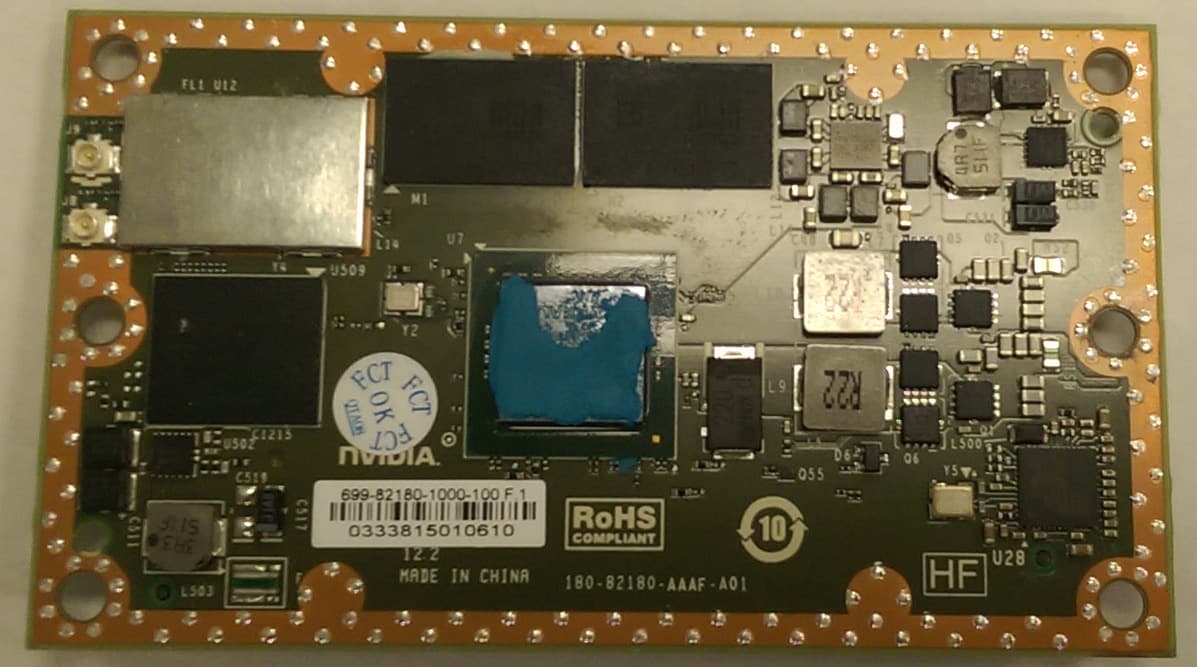
VOB-P2180
Nov 04, 2015WLAN 2X2 MIMO 802.11a/b/g/n/ac with Bluetooth
Equipment Class
DSS - Part 15 Spread Spectrum Transmitter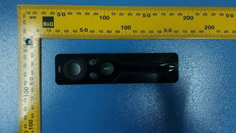
VOB-P2575
Apr 08, 2015Remote Control
Equipment Class
DSS - Part 15 Spread Spectrum Transmitter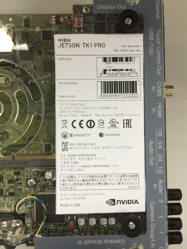
VOB-P1860
Apr 01, 2015Development Platform
Equipment Class
NII - Unlicensed National Information Infrastructure TX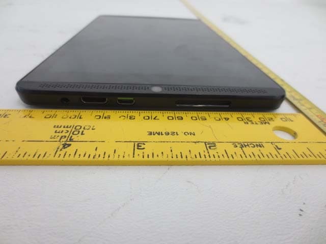
VOB-P1761WX
Mar 15, 2015Tablet
Equipment Class
DTS - Digital Transmission System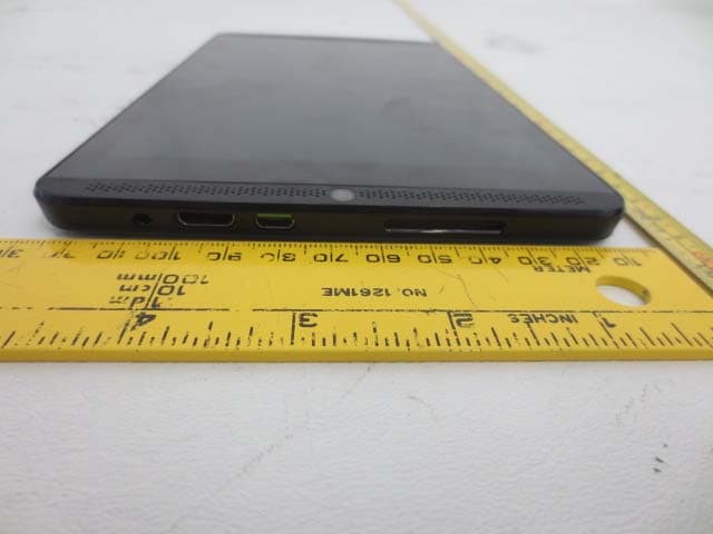
VOB-P1761W
Jun 15, 2014Tegra K1 Tablet
Equipment Class
DSS - Part 15 Spread Spectrum Transmitter