VOB-P2575Remote Control
NVIDIA Corporation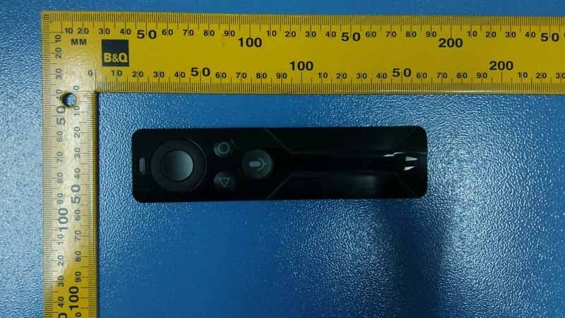
Click to zoom
Application Details
- Equipment Class
- DSS - Part 15 Spread Spectrum Transmitter
- Date of Grant
- Apr 08, 2015
- Application Purpose
- Original Equipment
- Date of Application
- Apr 07, 2015
- Equipment Note
- Remote Control
- Frequency Range
- 2402.00000000 - 2480.00000000
- Company
- NVIDIA Corporation
- Country
- United States
Documents & Files
Document Text
Text extracted from the exhibit documents filed with the FCC. Open a document above to read the original.
Users Manual
i SHIELD Remote Table of Contents ii Table of Contents About Your SHIELD remote .......................................................................................................... 1 using your shield remote ................................................................................................................. 2 Shield Remote ............................................................................................................................. 2 How to Connect Your remote to a shield device ............................................................................ 4 How to Connect Your remote ..................................................................................................... 4 How to Connect Your remote ..................................................................................................... 4 How to Reconnect the remote ......................................................................................................... 5 HOW TO TROUBLESHOOT CONNECTION PROBLEMS ................................................... 5 How to Charge Your remote ........................................................................................................... 6 How to ......................................................................................................................................... 6 How to CHECK the REMOTE BATTERY LEVEL ...................................................................... 6 Using your remote........................................................................................................................... 7 Using headphones with your remote............................................................................................... 9 Compliance...................................................................................................14 1 ABOUT YOUR SHIELD REMOTE Your NVIDIA® SHIELD™ remote makes it easy to access all of your favorite movies, music, and TV on your SHIELD device, with familiar navigation buttons and integrated voice search capability. Your remote includes the following features: • Navigation D-pad and center Select button • Familiar Android Back and Home buttons • Integrated microphone for voice search • Stereo headphone jack for private listening • Volume control* • Bluetooth connectivity for easy control without line of site • Internal rechargeable battery and USB charging cable Your SHIELD remote is compatible with all SHIELD devices. * Your TV or A/V receiver must support HDMI-CEC system volume control in order to the control volume level of those devices. Otherwise, the volume control will mute and unmute only. If headphones are plugged in, SHIELD remote can control the volume level of the headphones. 2 USING YOUR SHIELD REMOTE The SHIELD remote box includes one SHIELD remote, one USB charging cable, one Support Guide, and one Quick Start Guide. SHIELD REMOTE Integrated microphone D-pad SHIELD Remote 3 Select Button Back button Home button Voice search button with indicator light Volume touch control 4 HOW TO CONNECT YOUR REMOTE TO A SHIELD DEVICE The first time you use your SHIELD remote, you must establish a connection with a SHIELD device. This connection is saved for future use. HOW TO CONNECT YOUR REMOTE NOTE If you connect the remote to another SHIELD device, the previous connection is removed. Follow the steps in this procedure to establish the connection again. • On your SHIELD device, open the SHIELD accessories app and select Add an accessory. • Press the center Select button on your SHIELD remote to turn it on. The indicator light on the Voice search button will flash green to indicate that it is in connection mode. If the indicator light is not flashing, press and hold the Back and Home buttons for 5 seconds. • Once connected, your remote will appear in the SHIELD accessories menu along with a status of its battery level. HOW TO CONNECT YOUR REMOTE NOTE For mobile SHIELD devices, make sure that Bluetooth is enabled in Settings before trying to establish a connection. SHIELD Remote 5 HOW TO RECONNECT THE REMOTE Your remote automatically reconnects when the SHIELD device and the remote are turned on and in range. 1. Turn on your SHIELD device. 2. Turn on the remote by picking it up. NOTE You do not need to turn off your remote. It will sleep automatically when inactive. Simply pick it up again to turn it back on. HOW TO TROUBLESHOOT CONNECTION PROBLEMS • Verify that the remote has enough charge. • Verify that the remote’s indicator light is flashing at the same time that the SHIELD device is searching for an accessory. - On the remote, hold the Back and Home buttons for 5 seconds until the indicator light starts flashing. Open the SHIELD accessories app on your SHIELD device to initiate the connection process. • Verify that the SHIELD device has Bluetooth turned on. • Verify that only one remote or controller in range is attempting to connect to the SHIELD device. The connection process for one accessory must complete before you can connect another accessory. • Verify that only one SHIELD device in range is attempting to connect to the remote. • Verify that the SHIELD device has the latest system update. • If you are still having trouble, please contact customer support. 6 HOW TO CHARGE YOUR REMOTE Your remote's battery provides months of use on a full charge and up to 9 hours of private listening using the headphone jack. The remote charges from empty to full in 2 hours. 1. Plug the micro-USB end of the USB cable into the micro-USB slot of the remote. 2. Plug the standard USB end of the USB cable into a USB power source, such as an AC adapter or a USB port on SHIELD console. USB port. Connect the micro-USB end of the charging cable. NOTE A USB charging cable is provided in the box with your SHIELD remote. However, any Micro-USB charging cable can be used to charge the remote. HOW TO HOW TO CHECK THE REMOTE BATTERY LEVEL 1. Connect the remote to a SHIELD de…
Text truncated - open the document above for the full version.
External Photos
R AUDIX Technology (Shenzhen) Co., Ltd. FCC ID:VOB-P2575 page 15-1 Audix Technology (Shenzhen) Co., Ltd. Report No. ACS-F15082 15. PHOTOGRAPH OF EUT Figure 1 General Appearance of the EUT Figure 2 General Appearance of the EUT
ID Label/Location Info
NOTICE OF PROPRIETARY PROPERTY. THE INFORMATION CONTAINED HEREIN IS THE PROPRIETARY PROPERTY OF NVIDIA CORP. THE POSSESSOR AGREES TO THE FOLLOWING: (i) TO MAINTAIN THIS DOCUMENT IN CONFIDENCE,(ii) NOT TO REPRODUCE OR COPY IT (iii) NOT TO REVEAL OR PUBLISH IT IN WHOLE OR PART. Model: P2575 FCC ID: VOB-P2575 IC ID: 7361A-P2575 Label: Label Location: On the rear (back) side of the device. NVIDIA Proprietary and Confidential
Internal Photos
R AUDIX Technology (Shenzhen) Co., Ltd. FCC ID:VOB-P2575 page 15-2 Audix Technology (Shenzhen) Co., Ltd. Report No. ACS-F15082 Figure 3 General Appearance of the EUT Figure 4 Inside of the EUT R AUDIX Technology (Shenzhen) Co., Ltd. FCC ID:VOB-P2575 page 15-3 Audix Technology (Shenzhen) Co., Ltd. Report No. ACS-F15082 Figure 5 Inside of the EUT Figure 6 Inside of the EUT R AUDIX Technology (Shenzhen) Co., Ltd. FCC ID:VOB-P2575 page 15-4 Audix Technology (Shenzhen) Co., Ltd. Report No. ACS-F15082 Figure 7 Inside of the EUT Figure 8 Inside of the EUT R AUDIX Technology (Shenzhen) Co., Ltd. FCC ID:VOB-P2575 page 15-5 Audix Technology (Shenzhen) Co., Ltd. Report No. ACS-F15082 Figure 9 Inside of the EUT Figure 10 Inside of the EUT R AUDIX Technology (Shenzhen) Co., Ltd. FCC ID:VOB-P2575 page 15-6 Audix Technology (Shenzhen) Co., Ltd. Report No. ACS-F15082 Figure 11 Inside of the EUT Figure 12 Inside of the EUT R AUDIX Technology (Shenzhen) Co., Ltd. FCC ID:VOB-P2575 page 15-7 Audix Technology (Shenzhen) Co., Ltd. Report No. ACS-F15082 Figure 13 Inside of the EUT Figure 14 Inside of the EUT R AUDIX Technology (Shenzhen) Co., Ltd. FCC ID:VOB-P2575 page 15-8 Audix Technology (Shenzhen) Co., Ltd. Report No. ACS-F15082 Figure 15 Inside of the EUT
RF Exposure Info
Product Name:Remote Control Model Number: P2575 FCCID: VOB‐P2575 RADIO FRREQUENCY EXPOSURE COMPLIANCE RESULT : Test Standard : FCC KDB Publication 447498 D01 V05R02 Clause 4.3.1, The 1‐g and 10‐g SAR test exclusion thresholds for 100 MHz to 6 GHz at test separation distances ≤ 50 mm are determined by: [(max. power of channel, including tune‐up tolerance, mW)/(min. test separation distance, mm)] ∙ [√f (GHz) ] ≤ 3.0 for 1‐g SAR and ≤ 7.5 for 10‐g extremity SAR, where • f (GHz) is the RF channel transmit frequency in GHz • Power and distance are rounded to the nearest mW and mm before calculation • The result is rounded to one decimal place for comparison • 3.0 and 7.5 are referred to as the numeric thresholds in the step 2 below The test exclusions are applicable only when the minimum test separation distance is ≤ 50 mm and for transmission frequencies between 100 MHz and 6 GHz. When the minimum test separation distance is < 5 mm, a distance of 5 mm according to 5) in section 4.1 is applied to determine SAR test exclusion. According to the actual measurement, max. power of channel, including tune‐up tolerance =0.00009931mW min. test separation distance= 5mm √f (GHz) =1.55 The test result is 0.000031≤3.0 for 1‐g SAR≤ 7.5 for 10‐g SAR, hence the EUT is excluded from SAR evaluation according to FCC KDB Publication 447498 D01: General RF Exposure Guidance V05.
Test Report
R AUDIX Technology (Shenzhen) Co., Ltd. FCC ID:VOB-P2575 Audix Technology (Shenzhen) Co., Ltd. Report No. ACS-F15082 FCC PART 15C TEST REPORT FOR CERTIFICATION On Behalf of NVIDIA Corporation Remote Control Model No.: P2575 FCC ID: VOB-P2575 Prepared for : NVIDIA Corporation 2701 San Tomas Expressway, Santa Clara, CA, 95050, USA Prepared By : Audix Technology (Shenzhen) Co., Ltd. No. 6, Ke Feng Rd., 52 Block, Shenzhen Science & Industrial Park, Nantou, Shenzhen, Guangdong, China Tel: (0755) 26639496 Report Number ACS-F15082 Date of Test Mar.05~18, 2015 Date of Report Mar.30, 2015 R AUDIX Technology (Shenzhen) Co., Ltd. FCC ID:VOB-P2575 Audix Technology (Shenzhen) Co., Ltd. Report No. ACS-F15082 TABLE OF CONTENTS Description Page 1. SUMMARY OF STANDARDS AND RESULTS.......................................................... 1-1 1.1. Description of Standards and Results .................................................................................. 1-1 2. GENERAL INFORMATION ......................................................................................... 2-1 2.1. Description of Device (EUT) ............................................................................................... 2-1 2.2. Tested Supporting System Details ....................................................................................... 2-2 2.3. Block Diagram of connection between EUT and simulators ............................................... 2-2 2.4. Test information................................................................................................................... 2-2 2.5. Test Facility ......................................................................................................................... 2-3 2.6. Measurement Uncertainty (95% confidence levels, k=2) .................................................... 2-3 3. POWER LINE CONDUCTED EMISSION MEASUREMENT ................................. 3-1 3.1. Test Equipment .................................................................................................................... 3-1 3.2. Block Diagram of Test Setup............................................................................................... 3-1 3.3. Power Line Conducted Emission Test Limits...................................................................... 3-1 3.4. Configuration of EUT on Test ............................................................................................. 3-1 3.5. Operating Condition of EUT ............................................................................................... 3-2 3.6. Test Procedure ..................................................................................................................... 3-2 3.7. Conducted Emission at Mains Terminals Test Results ........................................................ 3-2 4. RADIATED EMISSION MEASUREMENT................................................................. 4-1 4.1. Test Equipment .................................................................................................................... 4-1 4.2. Block Diagram of Test Setup............................................................................................... 4-2 4.3. Radiated Emission Limit Standard: ..................................................................................... 4-3 4.4. EUT Configuration on Test ................................................................................................. 4-3 4.5. Operating Condition of EUT ............................................................................................... 4-3 4.6. Test Procedure ..................................................................................................................... 4-3 4.7. Radiated Emission Test Results ........................................................................................... 4-4 5. CONDUCTED SPURIOUS EMISSIONS...................................................................... 5-1 5.1. Test Equipment .................................................................................................................... 5-1 5.2. Limit..................................................................................................................................... 5-1 5.3. Test Procedure ..................................................................................................................... 5-1 5.4. Test result............................................................................................................................. 5-1 6. 20 DB BANDWIDTH TEST ........................................................................................... 6-1 6.1. Test Equipment .................................................................................................................... 6-1 6.2. Limit..................................................................................................................................... 6-1 6.3. Test Results .......................................................................................................................... 6-1 7. CARRIER FREQUENCY SEPARATION TEST ........................................................ 7-1 7.1. Test Equipment .................................................................................................................... 7-1 7.2. Limit..................................................................................................................................... 7-1 7.3. Test Results. ......................................................................................................................... 7-1 8. NUMBER OF HOPPING FREQUENCY TEST .......................................................... 8-1 8.1. Test Equipment .................................................................................................................... 8-1 8.2. Limit...............................................................................…
Text truncated - open the document above for the full version.
Test Setup Photos
R AUDIX Technology (Shenzhen) Co., Ltd. FCC ID:VOB-P2575 page 14-1 Audix Technology (Shenzhen) Co., Ltd. Report No. ACS-F15082 14. PHOTOGRAPH OF TEST 14.1.Photos of Power Line Conducted Emission Test R AUDIX Technology (Shenzhen) Co., Ltd. FCC ID:VOB-P2575 page 14-2 Audix Technology (Shenzhen) Co., Ltd. Report No. ACS-F15082 14.2.Photos of Radiated Emission Test 30-1000MHz R AUDIX Technology (Shenzhen) Co., Ltd. FCC ID:VOB-P2575 page 14-3 Audix Technology (Shenzhen) Co., Ltd. Report No. ACS-F15082 Above 1000MHz
Contact Information
Applicant
Charles Jackson
Test Firm
Audix Technology (Shenzhen) Co., Ltd.Smart Tsai
Technical Specifications
| # | Rule Parts | Frequency Range | Power Output |
|---|---|---|---|
| 1 | 15C | 2.40 GHz - 2.48 GHz | 9.93 mW |
Other Applications from NVIDIA Corporation
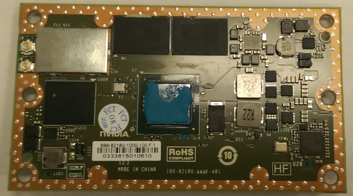
VOB-P2180
Nov 04, 2015WLAN 2X2 MIMO 802.11a/b/g/n/ac with Bluetooth
Equipment Class
DSS - Part 15 Spread Spectrum Transmitter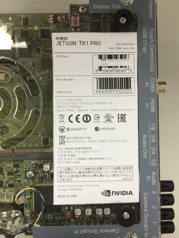
VOB-P1860
Apr 01, 2015Development Platform
Equipment Class
NII - Unlicensed National Information Infrastructure TX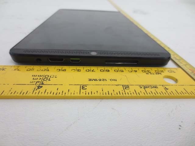
VOB-P1761WX
Mar 15, 2015Tablet
Equipment Class
DTS - Digital Transmission System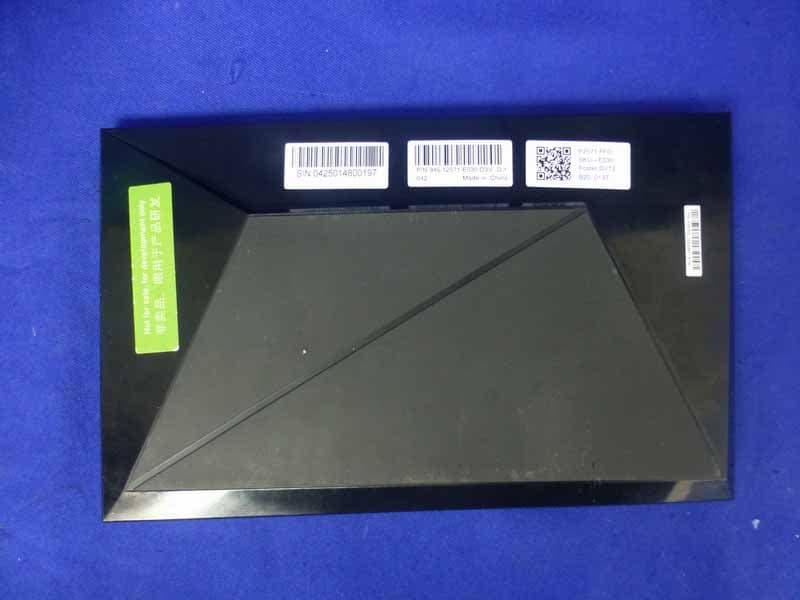
VOB-P2571
Mar 11, 2015Complex Set-Top Box
Equipment Class
DTS - Digital Transmission System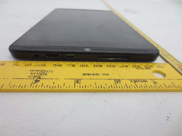
VOB-P1761W
Jun 15, 2014Tegra K1 Tablet
Equipment Class
DSS - Part 15 Spread Spectrum Transmitter