VPYLB1VYCommunication Module
Murata Manufacturing Co., Ltd.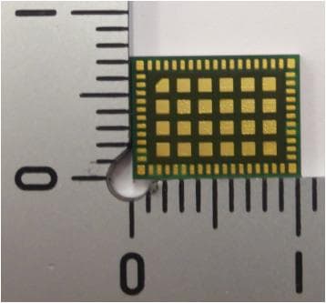
Click to zoom
Application Details
- Equipment Class
- DTS - Digital Transmission System
- Date of Grant
- Jan 06, 2020
- Application Purpose
- Original Equipment
- Date of Application
- Jan 06, 2020
- Equipment Note
- Communication Module
- Frequency Range
- 2402.00000000 - 2480.00000000
- Country
- Japan
Documents & Files
Document Text
Text extracted from the exhibit documents filed with the FCC. Open a document above to read the original.
Users Manual
1 Copyright © Murata Manufacturing Co., Ltd. All rights reserved. 18 December 2019 Type1VYUser Manual for FCC Since this module is not sold to general end users directly, there is no user manual of module. For the details about this module, please refer to the specification sheet of module. This module should be installed in the host device according to the interface specification (installation procedure). FCC ID:VPYLB1VY 2 Copyright © Murata Manufacturing Co., Ltd. All rights reserved. 18 December 2019 Type1VYUser Manual for FCC This device complies with part 15 of the FCC Rules. Operation is subject to the following two conditions: (1) This device maynot cause harmful interference, and (2) this device must accept any interference received, including interference that may cause undesired operation. This devicecomplies with below part 15 of FCC Rules. Part 15 Subpart C Part 15 Subpart E The modular transmitter is only FCC authorized for the specific rule parts (i.e., FCC transmitter rules) listed on the grant, and the host product manufacturer is responsible for compliance to any other FCC rules that apply to the host not covered by the modular transmitter grant of certification. The final host product still requires Part 15 Subpart B compliance testing with the modular transmitter installed. This module designed for mounting inside of the end product by us professionally. Therefore, it complies with the antenna and transmission system requirements of §15.203. Since there is no space which indicates FCC ID on this module, FCC ID is indicated in a manual. If the FCC ID is not visible when the module is installed inside another device, then the module is installed must also display a label referring to the enclosed module. 3 Copyright © Murata Manufacturing Co., Ltd. All rights reserved. 18 December 2019 Type1VYUser Manual for FCC Antenna PortAntenna model NameAntenna TypeAntenna Gain Chain0M-d[2.4GHz] Dual Monopole antenna+0.93 dBi [5GHz] Dual Monopole antenna+1.04 dBi Chain1M-d[2.4GHz] Dual Monopole antenna+0.93 dBi [5GHz] Dual Monopole antenna+1.04 dBi M-2[2.4GHz] Monopole antenna+1.98 dBi S-2[2.4GHz] Slot antenna+1.97dBi S-5[5GHz] Slot antenna+1.98 dBi 4 Copyright © Murata Manufacturing Co., Ltd. All rights reserved. 18 December 2019 Type1VYUser Manual for FCC This transmitter must not be co-located or operated in conjunction with any other antenna or transmitter. Compliance with FCC requirement 15.407(c) Data transmission is always initiated by software, which is the passed down through the MAC, through the digital and analog baseband, and finally to the RF chip. Several special packets are initiated by the MAC. These are the only ways the digital baseband portion will turn on the RF transmitter, which it then turns off at the end of the packet. Therefore, the transmitter will be on only while one of the aforementioned packets is being transmitted. In other words, this device automatically discontinue transmission in case of either absence of information to transmit or operational failure. Frequency Tolerance: ±20 ppm ●The following statements must be described on the user manual of the host device of this module; FCC CAUTION Changes or modifications not expressly approved by the party responsible for compliance could void the user’s authority to operate the equipment. *If it is difficult to describe this statement on the host product due to the size, please describe in the User's manual. This device complies with part 15 of the FCC Rules. Operation is subject to the following two conditions: (1) This device maynot cause harmful interference, and (2) this device must accept any interference received, including interference that may cause undesired operation. or Contains Transmitter Module FCC ID:VPYLB1VYContains FCC ID: VPYLB1VY 5 Copyright © Murata Manufacturing Co., Ltd. All rights reserved. 18 December 2019 Type1VYUser Manual for FCC This equipment complies with FCC radiation exposure limits set forth for an uncontrolled environment and meets the FCC radio frequency (RF) Exposure Guidelines. This equipment should be installed and operated keeping the radiator at least 20cm or more away from person’s body. ●When installing it in a mobile equipment. Please describe the following warning to the manual. 6 Copyright © Murata Manufacturing Co., Ltd. All rights reserved. 18 December 2019 Type1VYUser Manual for FCC Note) Portable equipment : Equipment for which the spaces between human body and antenna are used within 20cm. Mobile equipment : Equipment used at position in which the spaces between human body and antenna exceeded 20cm. ●When installing it in a portable equipment. Please describe the following warning to the manual. It is necessary to take a SAR test with your set mounting this module (except to use only Bluetooth V4.2(BDR/EDR/LE)). Class II permissive change application is necessary using the SAR report. Please contact Murata. The available scientific evidence does not show that any health problems are associated with using low power wireless devices. There is no proof, however, that these low power wireless devices are absolutely safe. Low power Wireless devices emit low levels of radio frequency energy (RF) in the microwave range while being used. Whereas high levels of RF can produce health effects (by heating tissue), exposure of low-level RF that does not produce heating effects causes no known adverse health effects. Many studies of low-level RF exposures have not found any biological effects. Some studies have suggested that some biological effects might occur, but such findings have not been confirmed by additional research. Type1VY has been tested and found to comply with FCC radiation exposure limits set forth for an uncontrolled environment and meets the FCC radio frequency (RF) Exposure Guidelines.
External Photos
Type1VYExternalPhoto 2019/12/03
ID Label/Location Info
PVYLB1V o M FCCID:Y LB1V IC C77 : Y2- de l: Ty pe 1 VY SA 2 0 1 9 109 10.25mm 7.5mm Murata markΦ1.5mm 2Dmatrixcode 2.4×2.4mm ModelNameHightWidthSpacing 0.8mm0.8mm0.1mm Lot NoHightWidthSpacing 0.8mm0.7mm0.1mm Direction markΦ0.6mm The red part is the print design prohibited area Tpe1VYLabeldesign 2019/11/15 IfFCCIDandICNumberare 1.4mm, and when written at the same scale, the size is as shown on the left. The module is small and there is no space to write FCC ID and IC Number. Type1VY SA2019109 (For example)
Internal Photos
Type1VYInternalPhoto 2019/12/03
RF Exposure Info
UL Japan, Inc. Shonan EMC Lab. 1-22-3 Megumigaoka, Hiratsuka-shi, Kanagawa-ken, 259-1220 JAPAN Telephone : +81 463 50 6400 Facsimile : +81 463 50 6401 RF Exposure / MPE Calculation No. : 13004393S-A Applicant : Murata Manufacturin g Co., Ltd. Type of Equipment : Communication Module Model No. : T ype1VY FCC ID : VPYLB1VY Murata Manufacturing Co., Ltd. declares that Model: Type1VY complies with FCC radiation exposure requirement specified in the FCC Rule 2.1091 (for mobile). RF Exposure Calculations: The following information provides the minimum separation distance for the highest gain antenna provided with the “Type1VY“ as calculated from (B) Limits for General Population / Uncontrolled Exposure of TABLE 1- LIMITS FOR MAXIMUM PERMISSIBLE EXPOSURE (MPE) of §1.1310 Radiofrequency radiation exposure limits. This calculation is based on the highest EIRP possible from the system, considering maximum power and antenna gain, and considering a 1mW/cm^2 uncontrolled exposure limit. The Friis formula used was: Where P =48.94 mW (Maximum average output power) Time average was used for the above value in consideration of 6-minutes time-averaging Burst power average was used for the above value in consideration of worst condition. G =1.578 Numerical Antenna gain (Directional gain); equal to 1.98dBi r =20 cm (Separation distance) 0.01536 mW/cm 2 Power Density Result S = 2 4r GP S Even taking into account the tolerance, this device can be satisfied with the limits.
Test Report
Test report No. : 13004393S-A-R2 Page: 1 of 148 Issued date : December 23, 2019 FCC ID : VPYLB1VY UL Japan, Inc. Shonan EMC Lab. 1-22-3 Megumigaoka, Hiratsuka-shi, Kanagawa-ken, 259-1220 JAPAN Telephone : +81 463 50 6400 Facsimile : +81 463 50 6401Report Cover Page - 13-EM-F0429 Issue # 15.0 CERTIFICATE 1266.03 RADIO TEST REPORT Test Report No. : 13004393S-A-R2 Applicant : Murata Manufacturing Co., Ltd. Type of Equipment : Communication Module Model No. : Type1VY FCC ID : VPYLB1VY Test regulation : FCC Part 15 Subpart C: 2019 * Wireless LAN (2.4 GHz band) & Bluetooth low energy part Test Result : Complied (Refer to SECTION 3.2) 1.T his test report shall not be reproduced in full or partial, without the written approval of UL Japan, Inc. 2.The results in this report appl y only to the sample tested. 3. This sample tested is in compliance with the limits of the above re gulation. 4.The test results in this test report are traceable to the national or international standards. 5. This test report must not be used by the customer to claim product certification, approval, or endorsement by the A2LA accreditation bod y. 6. This test report covers Radio technical requirements. It does not cover administrative issues such as Manual or non-Radio test related Requirements. (if applicable) 7. The all test items in this test report are conducted b y UL Japan, Inc. Shonan EMC Lab. 8. The opinions and the interpretations to the result of the description in this report are outside scopes where UL Japan has been accredited. 9. The information provided from the customer for this report is identified in SECTION 1. 10. This report is a revised version of 13004393S-A-R1. 13004393S-A-R1 is replaced with this report. Date of test: September 3 to 23, 2019 Representative test engineer: Kazuya Noda Engineer Consumer Technology Division Approv ed by: Hikaru Shirasawa Engineer Consumer Technology Division The testing in which "Non-accreditation" is displayed is outside the accreditation scopes in UL Japan. There is no testing item of "Non-accreditation". Test report No. : 13004393S-A-R2 P age: 2 of 148 Issued date : December 23, 2019 F CC ID : VPYLB1VY UL Japan, Inc. Shonan EM C Lab. 1-22-3 Megumigaoka, Hiratsuka-shi, Kanagawa-ken, 259-1220 JAPAN Telephone : +81 463 50 6400 Facsimile : +81 463 50 6401 REVISION HISTORY Original Test Report No.: 13004393S-A Revision Test report No. Date Page revised Contents - ( Original)13004393S-A December 2, 2019 - - 1 13004393S-A-R1 December 11, 2019 11 Add ition to Spurious Emission: “Tx BT LE with Tx 11ac-40 5190 MHz, high power” “Chain-0 + Chain-1” “2402 MHz 2440 MHz 2480 MHz” 2 13004393S-A-R2 December 23, 2019 7 Addition: “Additional information of specification: ... except the mode of Confi g.5.” Test report No. : 13004393S-A-R2 P age: 3 of 148 Issued date : December 23, 2019 F CC ID : VPYLB1VY UL Japan, Inc. Shonan EM C Lab. 1-22-3 Megumigaoka, Hiratsuka-shi, Kanagawa-ken, 259-1220 JAPAN Telephone : +81 463 50 6400 Facsimile : +81 463 50 6401 Reference: Abbreviations (Including words undescribed in this report) A2LA The American Association for Laboratory Accreditation NS No signal detect. AC Alternating Current NSA Normalized Site Attenuation AFH Adaptive Frequency Hopping NVLAP National Voluntary Laboratory Accreditation Program AM Amplitude Modulation OBW Occupied Band Width Amp, AMP Amplifier OFDM Orthogonal Frequency Division Multiplexing ANSI American National Standards Institute P/M Power meter Ant, ANT Antenna PCB Printed Circuit Board AP Access Point PER Packet Error Rate Atten., ATT Attenuator PHY Physical Layer AV Average PK Peak BPSK Binary Phase-Shift Keying PN Pseudo random Noise BR Bluetooth Basic Rate PRBS Pseudo-Random Bit Sequence BT Bluetooth PSD Power Spectral Density BT LE Bluetooth Low Energy QAM Quadrature Amplitude Modulation BW BandWidth QP Quasi-Peak Cal Int Calibration Interval QPSK Quadri-Phase Shift Keying CCK Complementary Code Keying RBW Resolution Band Width Ch., CH Channel RDS Radio Data System CISPR Comite International Special des Perturbations Radioelectriques RE Radio Equipment CW Continuous Wave RF Radio Frequency DBPSK Differential BPSK RMS Root Mean Square DC Direct Current RSS Radio Standards Specifications DFS Dynamic Frequency Selection Rx Receiving DQPSK Differential QPSK SA, S/A Spectrum Analyzer DSSS Direct Sequence Spread Spectrum SG Signal Generator EDR Enhanced Data Rate SVSWR Site-Voltage Standing Wave Ratio EIRP, e.i.r.p. Equivalent Isotropically Radiated Power TR Test Receiver EMC ElectroMagnetic Compatibility Tx Transmitting EMI ElectroMagnetic Interference VBW Video BandWidth EN European Norm Vert. Vertical ERP, e.r.p. Effective Radiated Power WLAN Wireless LAN EU European Union EUT Equipment Under Test Fac. Factor FCC Federal Communications Commission FHSS Frequency Hopping Spread Spectrum FM Frequency Modulation Freq. Frequency GFSK Gaussian Frequency-Shift Keying GNSS Global Navigation Satellite System GPS Global Positioning System Hori. Horizontal ICES Interference-Causing Equipment Standard IEC International Electrotechnical Commission IEEE Institute of Electrical and Electronics Engineers IF Intermediate Frequency ILAC International Laboratory Accreditation Conference ISED Innovation, Science and Economic Development Canada ISO International Organization for Standardization JAB Japan Accreditation Board LAN Local Area Network LIMS Laboratory Information Management System MCS Modulation and Coding Scheme MRA Mutual Recognition Arrangement NIST National Institute of Standards and Technology Test report No. : 13004393S-A-R2 Page : 4 of 148 Issued date : December 23, 2019 FCC ID : VPYLB1VY UL Japan, Inc. Shonan EMC Lab. 1-22-3 Megumigaoka, Hiratsuka-shi, Kanagawa-ken, 259-1220 JAPAN Telephone : +81 463 50 6400 Facsimile : +81 463 50 6401 CONTENTS PAGE SECTION 1: Customer information ....................................................................................................... 5 SECTION 2: Equipment under test …
Text truncated - open the document above for the full version.
Test Setup Photos
Test report No. : 13004393S-A-R2 Page : 142 of 148 Issued date : December 23, 2019 FCC ID : VPYLB1VY UL Japan, Inc. Shonan EMC Lab. 1-22-3 Megumigaoka, Hiratsuka-shi, Kanagawa-ken, 259-1220 JAPAN Telephone : +81 463 50 6400 Facsimile : +81 463 50 6401 APPENDIX 3: Photographs of test setup Conducted Emission EUT Serial No. A-1 (WLAN) Antenna : Chain-0: Dual Monopole Antenna : Chain-1: Dual Monopole Antenna EUT Serial No. B-2 (WLAN) Antenna : Chain-0: Dual Monopole Antenna : Chain-1: Slot Antenna Test report No. : 13004393S-A-R2 Page : 143 of 148 Issued date : December 23, 2019 FCC ID : VPYLB1VY UL Japan, Inc. Shonan EMC Lab. 1-22-3 Megumigaoka, Hiratsuka-shi, Kanagawa-ken, 259-1220 JAPAN Telephone : +81 463 50 6400 Facsimile : +81 463 50 6401 Conducted Emission EUT Serial No. B-2 (WLAN) Antenna : Chain-0: Dual Monopole Antenna : Chain-1: Monopole Antenna EUT Serial No. A-9 (BLE) Test report No. : 13004393S-A-R2 Page : 144 of 148 Issued date : December 23, 2019 FCC ID : VPYLB1VY UL Japan, Inc. Shonan EMC Lab. 1-22-3 Megumigaoka, Hiratsuka-shi, Kanagawa-ken, 259-1220 JAPAN Telephone : +81 463 50 6400 Facsimile : +81 463 50 6401 Radiated Spurious Emission EUT: A-1(WLAN) Antenna: Chain-0: Dual Monopole Antenna Chain-1: Dual Monopole Antenna EUT: B-2(WLAN) Antenna: Chain-0: Dual Monopole Antenna Chain-1: Slot Antenna Fron t Front Rear (Below 1 GHz) Rear (Below 1 GHz) Rear (Above 1 GHz) Rear (Above 1 GHz) Test report No. : 13004393S-A-R2 Page : 145 of 148 Issued date : December 23, 2019 FCC ID : VPYLB1VY UL Japan, Inc. Shonan EMC Lab. 1-22-3 Megumigaoka, Hiratsuka-shi, Kanagawa-ken, 259-1220 JAPAN Telephone : +81 463 50 6400 Facsimile : +81 463 50 6401 Radiated Spurious Emission EUT: B-2(WLAN) Antenna: Chain-0: Dual Monopole Antenna Chain-1: Monopole Antenna EUT: A-9 (BTLE) Fron t Front Rear (Below 1 GHz) Rear (Below 1 GHz) Rear (Above 1 GHz) Rear (Above 1 GHz) Test report No. : 13004393S-A-R2 Page : 146 of 148 Issued date : December 23, 2019 FCC ID : VPYLB1VY UL Japan, Inc. Shonan EMC Lab. 1-22-3 Megumigaoka, Hiratsuka-shi, Kanagawa-ken, 259-1220 JAPAN Telephone : +81 463 50 6400 Facsimile : +81 463 50 6401 Pre-check of Worst Case Position Module X-axis Y-axis Z-axis Test report No. : 13004393S-A-R2 Page : 147 of 148 Issued date : December 23, 2019 FCC ID : VPYLB1VY UL Japan, Inc. Shonan EMC Lab. 1-22-3 Megumigaoka, Hiratsuka-shi, Kanagawa-ken, 259-1220 JAPAN Telephone : +81 463 50 6400 Facsimile : +81 463 50 6401 Pre-check of Worst Case Position Chain-0: Dual Monopole Antenna X-axis Y-axis Z-axis Test report No. : 13004393S-A-R2 Page : 148 of 148 Issued date : December 23, 2019 FCC ID : VPYLB1VY UL Japan, Inc. Shonan EMC Lab. 1-22-3 Megumigaoka, Hiratsuka-shi, Kanagawa-ken, 259-1220 JAPAN Telephone : +81 463 50 6400 Facsimile : +81 463 50 6401 Pre-check of Worst Case Position Chain-1: Slot Antenna X-axis Chain-1: Monopole Antenna X-axis Y-axis Y-axis Z-axis Z-axis End of Report
Contact Information
Applicant
KENJI HAYASHIKOSHI(SENIOR MANAGER)
Technical Contact
UL Japan, Inc.Toyokazu Imamura
[email protected]81-463-50-6400
1-22-3 Megumigaoka, Hiratsuka-shi · Kanagawa-ken · Japan
Test Firm
UL Japan, Inc. SHONAN EMC LABORATORYAkio Hayashi
[email protected]81-463-50-6400
Technical Specifications
| # | Rule Parts | Frequency Range | Power Output |
|---|---|---|---|
| 2 | 15C | 2.40 GHz - 2.48 GHz | 10.00 mW |
Other Applications from Murata Manufacturing Co., Ltd.
VPYLB2EA003
Sep 01, 2026Communication Module
Equipment Class
NII - Unlicensed National Information Infrastructure TXVPYLBWA0ZZ2JM
Mar 11, 2026Communication Module
Equipment Class
DTS - Digital Transmission System
VPYLB2TG
May 20, 2025Wireless Vibration Sensor Unit
Equipment Class
DTS - Digital Transmission SystemVPYLBEE5WV2GF
Jun 20, 2024Communication Module
Equipment Class
DTS - Digital Transmission System
VPYLB2GT
Mar 25, 2024LoRa Module
Equipment Class
DSS - Part 15 Spread Spectrum Transmitter