VPYLB2GTLoRa Module
Murata Manufacturing Co., Ltd.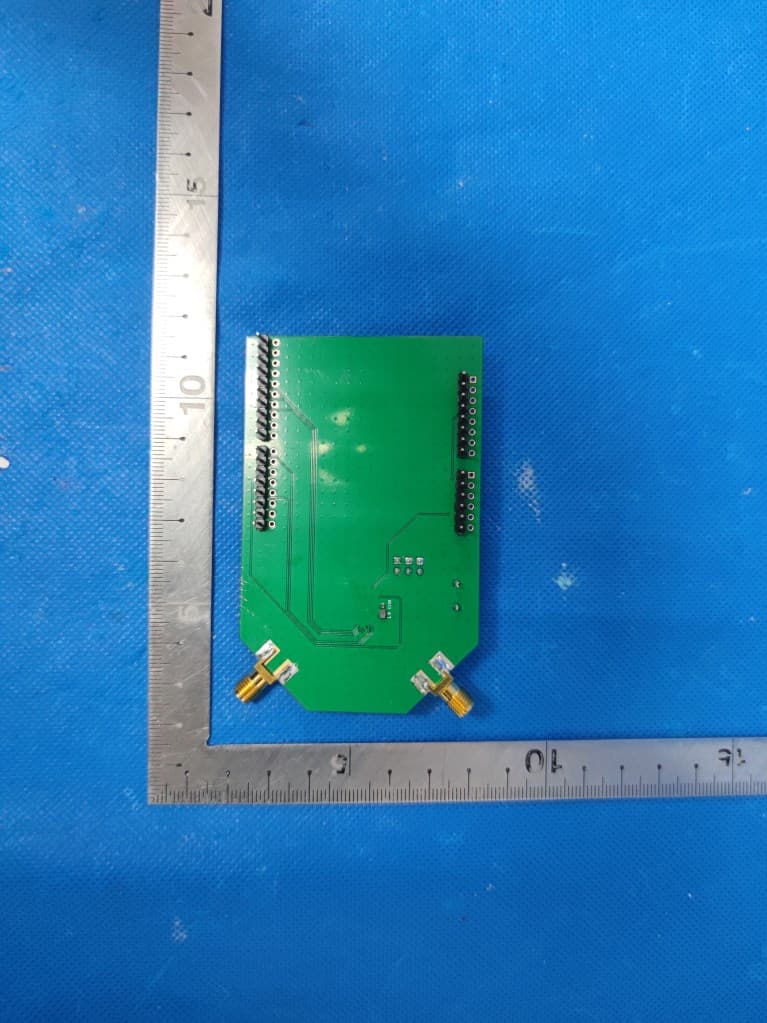
Click to zoom
Application Details
- Equipment Class
- DSS - Part 15 Spread Spectrum Transmitter
- Date of Grant
- Mar 25, 2024
- Application Purpose
- Original Equipment
- Date of Application
- Mar 25, 2024
- Equipment Note
- LoRa Module
- Frequency Range
- 902.20000000 - 927.80000000
- Country
- Japan
Documents & Files
Document Text
Text extracted from the exhibit documents filed with the FCC. Open a document above to read the original.
Users Manual
LoRa Module User Manual Part Number: LBAA0XV2GT LBAA0XV2GT has been FCC/ISED certified as Single Modular Approval with the following IDs. FCC ID: VPYLB2GTIC: 772C-LB2GT The module is limited to OEM installation ONLY. The OEM integrator is responsible for ensuring that the end-user has no manual instruction to remove or install module. Therefore, the final host product must be submitted to Murata for confirmation that the installation for the module into the host is in compliance with regulations of FCC and IC Canada. Specially, if an antenna other than the model documented in the Filing is used, a Class 2 Permissive Change must be filed with the FCC. Changes or modifications not expressly approved by the manufacturer could void the user’s authority to operate the equipment. This module has been approved by FCC to operate with the antenna types with the maximum permissible gain indicated. Antenna types not included in this list, having a gain greater than the maximum gain indicated for that type, are strictly prohibited for use with this device. The following antenna has been certified in combination with the module. Refer to the next pages for the antenna application guidance. ◼Whip antenna by Linxwith peak gains as 2.5dBi for 2.4GHz ISM band ◼Whip antenna by TE with peak gain as 2.0dBi for the sub-GHz band 2 18-230222 Antenna Application Guidance 2.4GHz antenna P/N: ANT-DB1-RAF-RPS Sub-GHz antenna P/N: 001-0002 Antenna Application Guidance PCB for assembly the antenna RP-SMA connector for 2.4GHz antennaRP-SMA connector for Sub-GHz antenna Length: 18.55 mm Width: 0.34 mm Length: 24.12 mm Width: 0.34 mm FCC Statements Pleasetakeattentionthatchangesormodificationsnotexpresslyapprovedbythepartyresponsiblefor compliancecouldvoidtheuser’sauthoritytooperatetheequipment. This device complies with Part 15 of the FCC Rules. Operation is subject to the following two conditions: (1) This device may not cause harmful interference, and (2) This device must accept any interference received, including interference that may cause undesired operation. This equipment complies with FCC/IC RSS-102 radiation exposure limits set forth for an uncontrolled environment. This equipment should be installed and operated with a minimum distance 20cm between the radiator & your body. When the FCC ID is not visible when the module is installed inside another device, then the outside of the device into which the module is installed must also display a label referring to the enclosed module. This exterior label can use wording ”Contains transmitter module FCC ID: VPYLB2GT” or “Contains FCC ID: VPYLB2GT”. FCC Statements (cont.) When the module is installed inside another device, the user manual of this device must contain below warning statements: 1. This device complies with Part 15 of the FCC Rules. Operation is subject to the following two conditions: (1) This device may not cause harmful interference, and (2) This device must accept any interference received, including interference that may cause undesired operation. 2. Changes or modifications not expressly approved by the party responsible for compliance could void the user's authority to operate the equipment. The devices must be installed and used in strict accordance with the manufacturer's instructions as described in the user documentation that comes with the product. The host product manufacturer is responsible for compliance to any other FCC rules that apply to the host not covered by the modular transmitter grant of certification. The final host product still requires Part 15 Subpart B compliance testing with the modular transmitter installed. The end user manual shall include all required regulatory information/warning as shown in this manual, include: This product must be installed and operated with a minimum distance of 20 cm between the radiator and user body. IC Statements This device complies with Industry Canada licence-exempt RSS standard(s). Operation is subject to the following two conditions: (1) this device may not cause interference, and (2) this device must accept any interference, including interference that may cause undesired operation of the device. Le présentappareilestconformeaux CNR d'IndustrieCanada applicablesaux appareilsradioexemptsde licence. L'exploitationestautoriséeaux deux conditions suivantes: (1) l'appareilne doit pas produirede brouillage, et (2) l'utilisateurde l'appareildoit accepter tout brouillageradioélectriquesubi, mêmesile brouillageest susceptible d'encompromettrele fonctionnement. Under Industry Canada regulations, this radio transmitter may only operate using an antenna of a type and maximum (or lesser) gain approved for the transmitter by Industry Canada. To reduce potential radio interference to other users, the antenna type and its gain should be so chosen that the equivalent isotropicallyradiated power (e.i.r.p.) is not more than that necessary for successful communication. Conformémentà la réglementationd'IndustrieCanada, le présentémetteurradio peut fonctionneravec uneantenned'un type et d'un gain maximal (ouinférieur) approuvépour l'émetteurpar IndustrieCanada. Dans le but de réduireles risquesde brouillageradioélectriqueà l'intentiondes autres utilisateurs, il faut choisirle type d'antenneet son gain de sorteque la puissance isotroperayonnée équivalente(p.i.r.e.) ne dépassepas l'intensiténécessaireà l'établissementd'unecommunication satisfaisante. IC Statements (cont.) This equipment complies with FCC/IC RSS-102 radiation exposure limits set forth for an uncontrolled environment. This equipment should be installed and operated with minimum distance 20cm between the radiator & your body. cematériel estconformeaux limitesde dose d'expositionaux rayonnements, FCC / CNR-102 énoncée dans un autreenvironnement.cetteeqipmentdevraitêtreinstalléet exploitéavec distance minimalede 20 entre le radiateuret votrecorps. When the Industry Canada certification number is not visible when the module is installed inside anoth…
Text truncated - open the document above for the full version.
Attestation Statements
Federal Communications Commission Authorization and Evaluation Division 7435 Oakland Mills Road Columbia, MD 21046 USA Date: March 3, 2023 Ref: Attestation Statements Part 2.911(d)(7) Filing [Murata Manufacturing Co., Ltd.] (“the applicant”) certifies that, as of the date of the filing of the application, [Murata Electronics North America, Inc.] is our designated U.S. agent for service of process.[Murata Manufacturing Co., Ltd.] accepts to maintain an agent for no less than one year after the grantee has terminated all marketing and importation or the conclusion of any Commission-related proceeding involving the equipment. [Murata Electronics North America, Inc.] accepts, as of the date of the filing of the application, the obligation of the designated U.S. agent for service of process. Sincerely, Designated U.S. Agent Information: Name: Murata Electronics North America, Inc. FRN: 0024753089 Contact Person: Mark E Tucker Address: 2200 Lake Park Drive Smyma, GA 30080-7604 United States Tel.: (678)684-2009 Email: [email protected] Mark E. Tucker 3/3/2023 U.S. Agent Signature: Applicant: Company Name: Murata Manufacturing Co., Ltd. Contact Person: Kenji Hayashikoshi Address: 10-1, Higashikotari 1-chome, Nagaokakyo-shi, Kyoto 617-8555 Japan Tel.: +81-75-955-6736 Email: [email protected] Applicant Signature:
Attestation Statements
Covered Equipment Certification Attestation Letter 3/14/2024 Nemko North America, Inc. 303 River Road Ottawa K1V 1H2 Canada ATTN.: Reviewing Engineer FCC ID: VPYLB2GT Murata Manufacturing Co., Ltd. (“the applicant”) certifies that the equipment for which authorization is sought is not “covered” equipment prohibited from receiving an equipment authorization pursuant to section 2.903 of the FCC rules. Note: If the equipment for which the applicant seeks authorization is produced by any of the entities identified on the current Covered List, the applicant should include an explanation on why the equipment is not “covered” equipment. Murata Manufacturing Co., Ltd. (“the applicant”) certifies that, as of the date of the filing of the application, the applicant is not identified on the Covered List as an entity producing “covered” equipment. Signed: Printed name: KENJI HAYASHIKOSHI Title: SENIOR MANAGER Company Name: Murata Manufacturing Co., Ltd. Date: 3/14/2024
Cover Letter(s)
Date (19/03/2024) Federal Communications Commission Equipment Authorization Branch 7435 Oakland Mills Road Columbia, MD 21046 Modular Approval Request FCC ID:VPYLB2GT The following attestation addresses the requirements to support modular approval: Modular approval requirement Yes (provide brief statement) No * (a) The radio elements must have the radio frequency circuitry shielded. Physical components and tuning capacitor(s) may be located external to the shield, but must be on the module assembly Refer to external photos. This module has shield cover. (b) The module must have buffered modulation/data inputs to ensure that the device will comply with Part 15 requirements with any type of input signal All inputs to the modules are buffered through logic or microprocessor inputs. Refer to Schematics. (c) The module must contain power supply regulation on the module The Module uses the chip with built-in power management components, the module ratedpower is 3.3V power, Refer to schematics. (d) The module must contain a permanently attached antenna, or contain a unique antenna connector, and be marketed and operated only with specific antenna(s), per Sections 15.203, 15.204(b), 15.204(c), 15.212(a), 2.929(b) The modular transmitter has two Dipole antenna, Refer to External photo. (e) The module must demonstrate compliance in a stand-alone configuration The modular transmitter is connected to the controlled board when testing. Please refer to setup photo. (f) The module must be labelled with its permanently affixed FCC ID label, or use an electronic display (See KDB Publication 784748 about labelling requirements) Refer to the label. (g) The module must comply with all specific rules applicable to the transmitter. The grantee must provide comprehensive instructions to explain compliance requirements Refer to manual Modular approval requirement Yes (provide brief statement) No * (h) The module must comply with RF exposure requirements The EUT meets RF exposure evaluation §2.1091, If the device built into a host as a portable usage, the additional RF exposure evaluation may be required as specified by §2.1093 * Please provide a detailed explanation if the answer is “No.” Sincerely, Signed: Printed name: Kenji Hayashikoshi Title: Dev. Sec. 6 Manager, Connectivity Module Dev. Dept., Communication Module Div.
Cover Letter(s)
3/14/2024 Nemko North America, Inc. 303 River Road Ottawa, Ontario, Canada K1V 1H2 REQUEST FOR CONFIDENTIALITY - FCC FCC ID: VPYLB2GT Pursuant to Sections 0.457(d)(1)(ii) and 0.459 of the Commission’s Rules and FCC Guidance document 726920, we hereby request confidential treatment of information accompanying this application as outlined below: PERMANENT LONG-TERM CONFIDENTIALITY: Schematics Bill of Materials/Parts List Block Diagrams Theory of Operation When the device is marketed before the requested number of days listed above, the grantee will inform the TCB to release the Short-Term Confidentiality information withheld on the FCC equipment authorization website. The above information contains trade secrets and proprietary information not customarily released to the public. The public disclosure of this information might be harmful to the applicant and provide unjustified benefits to its competitors. The Applicant understands that pursuant to Rule 0.457(d)(1)(ii), disclosure of this Application and all accompanying materials will not be made before the date of the Grant for this Application. Sincerely, Signed: Printed name: KENJI HAYASHIKOSHI Title: SENIOR MANAGER
External Photos
DEKRA Testing and Certification (Suzhou) Co., Ltd. No.99 Hongye Rd., Suzhou Industrial Park, Suzhou, 215006, Jiangsu, China TEL: +86-512-6251-5088 / FAX: +86-512-6251-5098 Report no.: 23B0020R-RF-External Photo Page 1 / 3 External Photographs EUT Photo(1) EUT Photo(2) DEKRA Testing and Certification (Suzhou) Co., Ltd. No.99 Hongye Rd., Suzhou Industrial Park, Suzhou, 215006, Jiangsu, China TEL: +86-512-6251-5088 / FAX: +86-512-6251-5098 Report no.: 23B0020R-RF-External Photo Page 2 / 3 EUT Photo(3) EUT Photo(4) DEKRA Testing and Certification (Suzhou) Co., Ltd. No.99 Hongye Rd., Suzhou Industrial Park, Suzhou, 215006, Jiangsu, China TEL: +86-512-6251-5088 / FAX: +86-512-6251-5098 Report no.: 23B0020R-RF-External Photo Page 3 / 3 EUT Photo(5) EUT Photo(6)
ID Label/Location Info
Company: Murata Manufacturing Co., Ltd. Add: 10-1, Higashikotari 1-chome, Nagaokakyo-shi, Kyoto 617-8555, Japan Tel: 81-75-955-6736 Fax: 81-75-955-6634 Label Location Justification Letter This justification is applicable to the LoRa Module identified as: Model: LBAA0XV2GT FCC ID: VPYLB2GT Since the module is too small to put the FCC ID even with the font size 4 points, we have to put the FCC ID on the user manual and packaging. Module appearance The module size is 9.98*8.70mm. There is not enough space to put the FCC ID besides other mandatory marking information. 8.70mm 9.98mm FCC ID on the packaging A label of certification IDs is sticking on the anti-humidity bag. Sincerely Yours, Signature: Typed or Printed Name: Kenji Hayashikoshi Title: Dev. Sec. 6 Senior Manager Connectivity Module Dev. Dept. Communication Module Div. Model: LBAA0XV2GT FCC ID: VPYLB2GT IC: 772C-LB2GT 湿度 インジケ-タ 乾燥 剤 表示 ラ べ ル 防湿 梱包 袋 表示 ラベル Label Label of certification IDs Desiccant Humidity Indicator Anti-humidity Plastic Bag
Internal Photos
DEKRA Testing and Certification (Suzhou) Co., Ltd. No.99 Hongye Rd., Suzhou Industrial Park, Suzhou, 215006, Jiangsu, China TEL: +86-512-6251-5088 / FAX: +86-512-6251-5098 Report no.: 2331052R-RF-Internal Photo Page 1 / 2 Internal Photographs EUT Photo(1) EUT Photo(2) DEKRA Testing and Certification (Suzhou) Co., Ltd. No.99 Hongye Rd., Suzhou Industrial Park, Suzhou, 215006, Jiangsu, China TEL: +86-512-6251-5088 / FAX: +86-512-6251-5098 Report no.: 2331052R-RF-Internal Photo Page 2 / 2 EUT Photo(3) —2.4G Antenna EUT Photo(4)—900M Antenna
RF Exposure Info
DEKRA Testing and Certification (Suzhou) Co., Ltd. No.99 Hongye Rd., Suzhou Industrial Park, Suzhou, 215006, Jiangsu, China TEL: +86-512-6251-5088 / FAX: +86-512-6251-5098 Test report No: 23B0020R-RF-US-P20V01 FCC Exposure TEST REPORT Product Name LoRa Module Trademark Murata FCC ID VPYLB2GT Model and /or type reference LBAA0XV2GT Applicant ́s name / address Murata Manufacturing Co., Ltd. 10-1, Higashikotari 1-chome, Nagaokakyo-shi, Kyoto 617-8555, Japan Test method requested, standard KDB 447498D01V06 FCC Part1.1310 Verdict Summary IN COMPLIANCE Documented By (name / position & signature) Feng Jiao/ Project Engineer Approved by (name / position & signature) Jack Zhang/ Manager Date of issue 2024-03-19 Report template No Template_FCC-MPE-RF-V1.0 DEKRA Testing and Certification (Suzhou) Co., Ltd. No.99 Hongye Rd., Suzhou Industrial Park, Suzhou, 215006, Jiangsu, China TEL: +86-512-6251-5088 / FAX: +86-512-6251-5098 Report no.: 23B0020R-RF-US-P20V01 Page 2 / 9 INDEX page Competences and Guarantees ............................................................................................................................. 3 General conditions ............................................................................................................................................... 3 Environmental conditions ..................................................................................................................................... 3 Possible test case verdicts ................................................................................................................................... 4 Abbreviations ....................................................................................................................................................... 4 Document History ................................................................................................................................................ 5 Remarks and Comments ..................................................................................................................................... 5 1. RF Exposure Evaluation .............................................................................................................................. 6 1.1. Limits .......................................................................................................................................................... 6 1.2. Test Procedure ........................................................................................................................................... 7 1.3. Test Result of RF Exposure Evaluation ....................................................................................................... 7 DEKRA Testing and Certification (Suzhou) Co., Ltd. No.99 Hongye Rd., Suzhou Industrial Park, Suzhou, 215006, Jiangsu, China TEL: +86-512-6251-5088 / FAX: +86-512-6251-5098 Report no.: 23B0020R-RF-US-P20V01 Page 3 / 9 COMPETENCES AND GUARANTEES DEKRA is a testing laboratory competent to carry out the tests described in this report. In order to assure the traceability to other national and international laboratories, DEKRA has a calibration and maintenance program for its measurement equipment. DEKRA guarantees the reliability of the data presented in this report, which is the result of the measurements and the tests performed to the item under test on the date and under the conditions stated in the report and it is based on the knowledge and technical facilities available at DEKRA at the time of performance of the test. DEKRA is liable to the client for the maintenance of the confidentiality of all information related to the item under test and the results of the test. The results presented in this Test Report apply only to the particular item under test established in this document. IMPORTANT: No parts of this report may be reproduced or quoted out of context, in any form or by any means, except in full, without the previous written permission of DEKRA. GENERAL CONDITIONS Test Location No. 99, Hongye Road, Suzhou Industrial Park Suzhou, 215006, P.R. China Date(receive sample) Nov. 02, 2023 Date (start test) Nov. 03, 2023 Date (finish test) Dec. 13, 2023 1. This report is only referred to the item that has undergone the test. 2. This report does not constitute or imply on its own an approval of the product by the Certification Bodies or Competent Authorities. 3. This document is only valid if complete; no partial reproduction can be made without previous written permission of DEKRA. 4. This test report cannot be used partially or in full for publicity and/or promotional purposes without previous written permission of DEKRA. ENVIRONMENTAL CONDITIONS The climatic conditions during the tests are within the limits specified by the manufacturer for the operation of the EUT and the test equipment. The climatic conditions during the tests were within the following limits: Ambient temperature 15 °C – 35 °C Relative Humidity air 30% - 60% If explicitly required in the basic standard or applied product / product family standard the climatic values are recorded and documented separately in this test report. DEKRA Testing and Certification (Suzhou) Co., Ltd. No.99 Hongye Rd., Suzhou Industrial Park, Suzhou, 215006, Jiangsu, China TEL: +86-512-6251-5088 / FAX: +86-512-6251-5098 Report no.: 23B0020R-RF-US-P20V01 Page 4 / 9 POSSIBLE TEST CASE VERDICTS Test case does not apply to test object N/A Test object does meet requirement P (Pass) / PASS Test object does not meet requirement F (Fail) / FAIL Not measured N/M ABBREVIATIONS For the purposes of the present document, the following abbreviations apply: EUT : Equipment Under Test QP : Quasi-Peak CAV : CISPR Average AV : Average CDN : Coupling Decoupling Network SAC : Semi-Anechoic Chamber OATS : Open Area Test Site BW : Bandwidth AM : Amplitude Modulation PM : Pulse Modulation HCP : Horizontal Coupling Plane VCP : Vertical Coupling Plane U N : Nominal volta…
Text truncated - open the document above for the full version.
Test Report
DEKRA Testing and Certification (Suzhou) Co., Ltd. No.99 Hongye Rd., Suzhou Industrial Park, Suzhou, 215006, Jiangsu, China TEL: +86-512-6251-5088 / FAX: +86-512-6251-5098 Test report No: 23B0020R-RF-US-P06V01 FCC&ISED TEST REPORT Product Name LoRa Module Trademark Murata Model and /or type reference LBAA0XV2GT FCC ID VPYLB2GT IC 772C-LB2GT Applicant ́s name / address Murata Manufacturing Co., Ltd. 10-1, Higashikotari 1-chome, Nagaokakyo-shi, Kyoto 617-8555, Japan Test method requested, standard FCC CFR Title 47 Part 15 Subpart C Section 15.247 ANSI C63.10: 2013 RSS-Gen Issue 5 / RSS-247 Issue 3 Verdict Summary IN COMPLIANCE Tested by (name / position & signature) Feng Jiao/ Project Engineer Approved by (name / position & signature) Jack Zhang/ Manager Date of issue 2024-03-20 Report Version V1.1 Report template No Template_FCC 15.247-RF-V1.0 DEKRA Testing and Certification (Suzhou) Co., Ltd. No.99 Hongye Rd., Suzhou Industrial Park, Suzhou, 215006, Jiangsu, China TEL: +86-512-6251-5088 / FAX: +86-512-6251-5098 Report no.: 23B0020R-RF-US-P06V01 Page 2 / 163 INDEX page Competences and Guarantees ............................................................................................................................. 5 General conditions ............................................................................................................................................... 5 Environmental conditions ..................................................................................................................................... 5 Possible test case verdicts ................................................................................................................................... 6 Abbreviations ....................................................................................................................................................... 6 Document History ................................................................................................................................................ 7 Remarks and Comments ..................................................................................................................................... 7 Used Equipment .................................................................................................................................................. 8 Uncertainty ........................................................................................................................................................ 10 1 General Information .................................................................................................................................. 11 1.1 General Description of the Item(s) ................................................................................................... 11 1.2 Antenna Information ........................................................................................................................ 13 1.3 Channel List .................................................................................................................................... 14 1.4 Power Setting .................................................................................................................................. 18 2 Description of Test Setup .......................................................................................................................... 19 2.1 Operating mode(s) used for tests .................................................................................................... 19 2.2 Support / Auxiliary equipment / unit / Test software for the EUT ....................................................... 19 2.3 Test Configuration / Block diagram used for tests ............................................................................ 20 2.4 Testing process ............................................................................................................................... 21 3 Verdict summary section ........................................................................................................................... 22 3.1 Standards ....................................................................................................................................... 22 3.2 Overview of results .......................................................................................................................... 23 3.3 Test Facility ..................................................................................................................................... 24 4 Test Results .............................................................................................................................................. 25 4.1 AC Power Line Conducted Emission ............................................................................................... 25 4.1.1 Limit ...................................................................................................................................... 25 4.1.2 Test Setup ............................................................................................................................. 25 4.1.3 Test Procedure ...................................................................................................................... 25 4.1.4 Test Data .............................................................................................................................. 26 4.2 Emissions in restricted frequency bands .......................................................................................... 27 4.2.1 Limit ...................................................................................................................................... 27 4.2.2 Test Setup ............................................................................................................................. 29 4.2.3 Test Procedure ............................................…
Text truncated - open the document above for the full version.
Test Report
DATA AND DEVICES / 001-0002 001-0002 Dipole Antenna 902-928 MHz ELECTRICAL SPECIFICATIONS Operating Frequency (MHz)902-928 VSWR – Avg≤2.5:1 Gain (dBi)2.0 Nominal Impedance (Ohms)50 PolarizationLinear vertical MECHANICAL SPECIFICATIONS Dimensions – height x diameter – mm (in.)196.0 x 12.5 (7.72 x 0.49) Weight – g (oz.)13.0 (0.46) Antenna ColorBlack PART NUMBERDESCRIPTION 001-0002900 MHz dipole antenna for reverse polarity SMA connector 080-0001U.FL to reverse polarity SMA cable, 105 mm ENVIRONMENTAL SPECIFICATIONS Operating Temperature – °C (°F)-20 to +65°C (-4 to +149°F) UL RatingUL 94HB Material Substance ComplianceRoHS DATA AND DEVICES / 001-00022 MECHANICAL DRAWING RADIATION PATTERNS Extended Position, Vertical DATA AND DEVICES / 001-0002 te.com TE, and TE connectivity (logo) are trademarks owned or licensed by the TE Connectivity Ltd. family of companies. All other logos, products and/or company names referred to herein might be trademarks of their respective owners. The information given herein, including drawings, illustrations and schematics which are intended for illustration purposes only, is believed to be reliable. However, TE Connectivity makes no warranties as to its accuracy or completeness and disclaims any liability in connection with its use. TE Connectivity‘s obligations shall only be as set forth in TE Connectivity‘s Standard Terms and Conditions of Sale for this product and in no case will TE Connectivity be liable for any incidental, indirect or consequential damages arising out of the sale, resale, use or misuse of the product. Users of TE Connectivity products should make their own evaluation to determine the suitability of each such product for the specific application. TE Connectivity warrants to the original end user customer of its products that its products are free from defects in material and workmanship. Subject to conditions and limitations TE Connectivity will, at its option, either repair or replace any part of its products that prove defective because of improper workmanship or materials. This limited warranty is in force for the useful lifetime of the original end product into which the TE Connectivity product is installed. Useful lifetime of the original end product may vary but is not warrantied to exceed one (1) year from the original date of the end product purchase. ©2022 TE Connectivity. All Rights Reserved. 08/22 Original USA: +1 (800) 522-6752 Canada: +1 (905) 475-6222 Mexico: +52 (0) 55-1106-0800 Latin/S. America: +54 (0) 11-4733-2200 Germany: +49 (0) 6251-133-1999 UK: +44 (0) 800-267666 France: +33 (0) 1-3420-8686 Netherlands: +31 (0) 73-6246-999 China: +86 (0) 400-820-6015 TE TECHNICAL SUPPORT CENTER Folded Position, Vertical
Test Report
DEKRA Testing and Certification (Suzhou) Co., Ltd. No.99 Hongye Rd., Suzhou Industrial Park, Suzhou, 215006, Jiangsu, China TEL: +86-512-6251-5088 / FAX: +86-512-6251-5098 Report no.: 23B0020R-RF-US-P06V01 Page 85 / 163 2.4GHz FSK Channel00 2402MHz Channel78 2480MHz Channel00 2402MHz Channel39 2441MHz Channel78 2480MHz DEKRA Testing and Certification (Suzhou) Co., Ltd. No.99 Hongye Rd., Suzhou Industrial Park, Suzhou, 215006, Jiangsu, China TEL: +86-512-6251-5088 / FAX: +86-512-6251-5098 Report no.: 23B0020R-RF-US-P06V01 Page 86 / 163 812kHz LoRa Channel00 2403MHz Channel76 2479MHz Channel00 2403MHz Channel39 2442MHz Channel76 2479MHz DEKRA Testing and Certification (Suzhou) Co., Ltd. No.99 Hongye Rd., Suzhou Industrial Park, Suzhou, 215006, Jiangsu, China TEL: +86-512-6251-5088 / FAX: +86-512-6251-5098 Report no.: 23B0020R-RF-US-P06V01 Page 87 / 163 SubG CSS Channel01 902.5 MHz Channel01 902.5MHz Channel16 914.5MHz Channel16 914.5MHz Channel31 926.5MHz Channel31 926.5MHz DEKRA Testing and Certification (Suzhou) Co., Ltd. No.99 Hongye Rd., Suzhou Industrial Park, Suzhou, 215006, Jiangsu, China TEL: +86-512-6251-5088 / …
Text truncated - open the document above for the full version.
Contact Information
Applicant
KENJI HAYASHIKOSHI(SENIOR MANAGER)
Test Firm
DEKRA Testing and Certification (Suzhou) Co., Ltd.Janet Xu
[email protected]86 512 6251 50885113
Technical Specifications
| # | Rule Parts | Frequency Range | Power Output |
|---|---|---|---|
| 3 | 15C | 902.2 MHz - 927.8 MHz | 139.00 mW |
Other Applications from Murata Manufacturing Co., Ltd.
VPYLB2EA003
Sep 01, 2026Communication Module
Equipment Class
NII - Unlicensed National Information Infrastructure TXVPYLBWA0ZZ2JM
Mar 11, 2026Communication Module
Equipment Class
DTS - Digital Transmission System
VPYLB2TG
May 20, 2025Wireless Vibration Sensor Unit
Equipment Class
DTS - Digital Transmission SystemVPYLBEE5WV2GF
Jun 20, 2024Communication Module
Equipment Class
DTS - Digital Transmission System
VPYLBEE6XX1UR
Oct 15, 2023Communication module
Equipment Class
NII - Unlicensed National Information Infrastructure TX