VPYLBVKCC3000 Wireless Module
Murata Manufacturing Co., Ltd.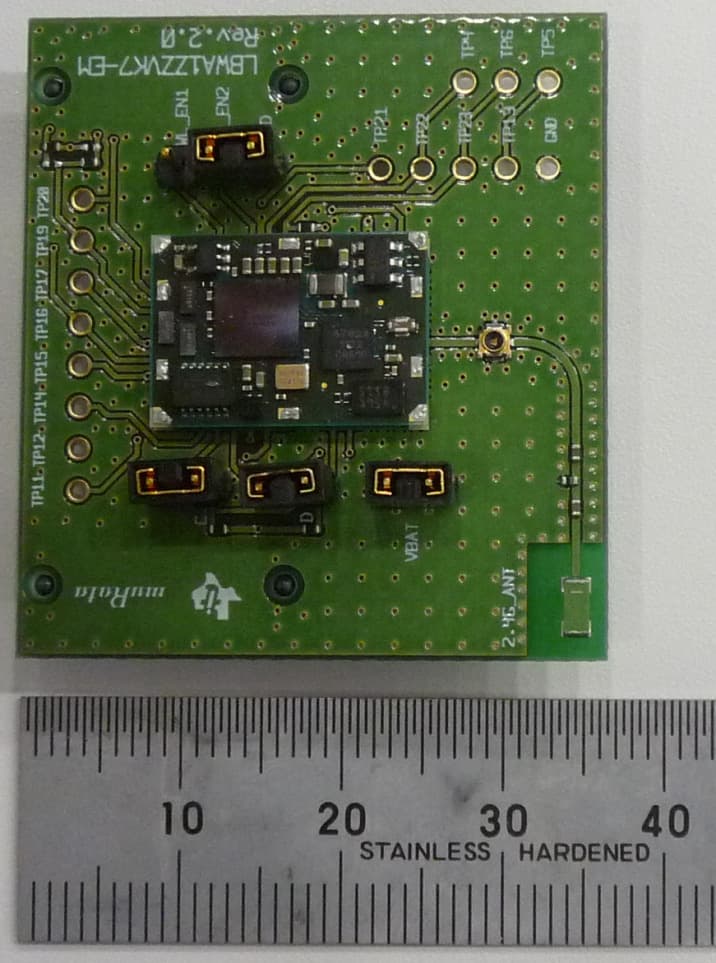
Click to zoom
Application Details
- Equipment Class
- DTS - Digital Transmission System
- Date of Grant
- Feb 23, 2012
- Application Purpose
- Original Equipment
- Date of Application
- Feb 23, 2012
- Equipment Note
- CC3000 Wireless Module
- Frequency Range
- 2412.00000000 - 2462.00000000
- Country
- Japan
Documents & Files
Document Text
Text extracted from the exhibit documents filed with the FCC. Open a document above to read the original.
Users Manual
LBWA1ZZVK7User Manual Notice (1) Please describe the following warning on the final product which contains this module. Please describe the following warning to the manual . Contains Transmitter Module IC: 772C-LBVK Contains IC: 772C-LBVK or Please describe a mark requirement and minimum prod uct operation procedure by both English and French. Please describe the following warning to the manual . When the SAR examination is necessary in a portable composition in the mobile equipment. Please describe a mark requirement and minimum prod uct operation procedure by both English and French. Note) Portable equipment : Equipment for which the spaces between human body and antenna are used within 20c m. Mobile equipment : Equipment used at position in wh ich the spaces between human body and antenna excee ded 20cm.. Notice (2) Please describe the following warning to the manual . Note) The description of the last SAR value is arbi trary. Please describe a mark requirement and minimum prod uct operation procedure by both English and French. When the SAR examination is necessary in the Portab le equipment. Notice (3)
Users Manual
P.1 USER MANUAL STATEMENTS For OEM integration only – device cannot be sold to general public. Therefore we will not supply the User’s manual. However, we will ask OEM to include the following statements required by FCC on the product and in the User’s manual. P.2 OEM LABELING REQUIREMENTS FOR END-PRODUCT Please describe the following warning on the final product which contains this module. “Contains Transmitter Module FCC ID: VPYLBTN” or “Contains FCC ID: VPYLBTN” This device complies with Part 15 of the FCC Rules. Operation is subject to the following two conditions: (1) this device may not cause harmful interference, and (2) this device must accept any interference received, including interference that may cause undesired operation. OEM END PRODUCT USER MANUAL STATEMENTS Please describe the following warning to the manual. FCC WARNING Changes or modifications not expressly approved by the party responsible for compliance could void the user’s authority to operate the equipment. This transmitter must not be co-located or operated in conjunction with any other antenna or transmitter. OEM END PRODUCT USER MANUAL STATEMENTS When installing it in a mobile equipment, This equipment complies with FCC radiation exposure limits set forth for an uncontrolled environment and meets the FCC radio frequency (RF) Exposure Guidelines in Supplement C to OET65. This equipment should be installed and operated keeping the radiator at least 20cm or more away from person’s body (excluding extremities: hands, wrists, feet and ankles) When installing it in a portable equipment The available scientific evidence does not show that any health problems are associated with using low power wireless devices. There is no proof, however, that these low power wireless devices are absolutely safe. Low power Wireless devices emit low levels of radio frequency energy (RF) in the microwave range while being used. Whereas high levels of RF can produce health effects (by heating tissue), exposure of low-level RF that does not produce heating effects causes no known adverse health effects. Many studies of low-level RF exposures have not found any biological effects. Some studies have suggested that some biological effects might occur, but such findings have not been confirmed by additional research. [Model Name] has been tested and found to comply with FCC radiation exposure limits set forth for an uncontrolled environment and meets the FCC radio frequency (RF) Exposure Guidelines in Supplement C to OET65. The maximum SAR levels tested for [Model Name] has been shown to be [SAR measurement value] W/kg at Body. Note) Portable equipment: Equipment for which the spaces between human body and antenna are used within 20cm. Mobile equipment: Equipment used at position in which the spaces between human body and antenna exceeded 20cm. P.3 OEM LABELING REQUIREMENTS FOR END-PRODUCT Please describe the following warning on the final product which contains this module “Contains Transmitter Module IC: 772C-LBVK” or “Contains IC: 772C-LBVK” Please describe the following warning to the manual. This device complies with Industry Canada licence-exempt RSS standard(s). Operation is subject to the following two conditions: (1) this device may not cause interference, and (2) this device must accept any interference, including interference that may cause undesired operation of the device. Le présent appareil est conforme aux CNR d'Industrie Canada applicables aux appareils radio exempts de licence. L'exploitation est autorisée aux deux conditions suivantes : (1) l'appareil ne doit pas produire de brouillage, et (2) l'utilisateur de l'appareil doit accepter tout brouillage radioélectrique subi, même si le brouillage est susceptible d'en compromettre le fonctionnement. Please describe a mark requirement and minimum product operation procedure by both English and French. OEM END PRODUCT USER MANUAL STATEMENTS Please describe the following warning to the manual. When the SAR examination is necessary in a portable composition in the mobile equipment, This equipment complies with IC radiation exposure limits set forth for an uncontrolled environment and meets RSS-102 of the IC radio frequency (RF) Exposure rules. This equipment should be installed and operated keeping the radiator at least 20cm or more away from person’ s body (excluding extremities: hands, wrists, feet and ankles). Cetéquipement est conforme aux limites d’ exposition aux rayonnementsénoncées pour un environnement non contrôléet respecte les règles d ’ exposition aux fréquences radioélectriques (RF) CNR-102 de l’ IC. Cet équipement doitêtre installéet utiliséen gardant une distance de 20 cm ou plus entre le dispositif rayonnant et le corps (àl’ exception des extrémités : mains, poignets, pieds et chevilles). Please describe a mark requirement and minimum product operation procedure by both English and French. Note) Portable equipment: Equipment for which the spaces between human body and antenna are used within 20cm. Mobile equipment: Equipment used at position in which the spaces between human body and antenna exceeded 20cm. Please describe the following warning to the manual. When the SAR examination is necessary in the Portable equipment, The available scientific evidence does not show that any health problems are associated with using low power wireless devices. There is no proof, however, that these low power wireless devices are absolutely safe. Low power Wireless devices emit low levels of radio frequency energy (RF) in the microwave range P.4 while being used. Whereas high levels of RF can produce health effects (by heating tissue), exposure of low-level RF that does not produce heating effects causes no known adverse health effects. Many studies of low-level RF exposures have not found any biological effects. Some studies have suggested that some biological effects might occur, but such findings have not been confirmed by additional research. [Model Name] has been teste…
Text truncated - open the document above for the full version.
External Photos
LBWA1ZZVK7 Product Photos LBWA1ZZVK7 Photos 2011/07/27 Top View and Bottom View with Shield Top View and Bottom View without Shield LBWA1ZZVK7 with Antenna Photos Top View with Shield Top View without Shield Bottom V iew Antenna Antenna
ID Label/Location Info
Label Example Item (1) (2) (3) (4) (5) Display Item Model No. Attestation ID etc. Code Direction mark Logo of Manufacture Content LBWA1ZZVK7 KM123456 Model: LBWA1ZZVK7 IC: 772C-LBVK (1)(2)(3) (5) (4) KM123456 FCC ID: VPYLBVK
Internal Photos
LBWA1ZZVK7 Product Photos LBWA1ZZVK7 Photos 2011/07/27 Top View and Bottom View with Shield Top View and Bottom View without Shield LBWA1ZZVK7 with Antenna Photos Top View with Shield Top View without Shield Bottom V iew Antenna Antenna
Operational Description
Preliminary Specification of CHIP MULTILAYER ANTENNA Written by R.Imai Preliminary SPEC No. : NAN68-PA0001C Checked by T. Isa Part Number : see below table Date 4/Sep./2007 C>1reel : 3,000pcs A>Rev. by Y.K. on 09/Sep./’09, B>Rev. by Y.K. on 30/Oct./’09, C>Rev. by M.K. on 12/Aug./’10 - MURATA MFG. CO., LTD. - 1/3 Please refer to the latest specification before using this product since the preliminary specification could be revised without notice. This is a preliminary specification of LDA31 series for 2.4GHz band. 1. Electrical Characteristics (at –40 degree C to +85 degree C) Murata P/N Center frequency [MHz] Tolerance of center frequency [MHz] Nominal Impedance [ohm] Power Capacity [mW max] LDA312G7313F-2372730+/- 68 LDA313G0313F-2403030+/- 76 LDA313G3313F-2433330+/- 84 50500 Murata P/N Center frequency [MHz] Tolerance of center frequency [MHz] Nominal Impedance [ohm] Power Capacity [mW max] LDA315G2013F-2465200+/- 135 LDA316G2013F-2506200+/- 162 50500 Note: The above-mentioned values have been obtained according to our own measuring methods (testing jig: Fig.1, Fig.2 ,Zo=50 W) and may vary depending on the circuit, in which this component is actually incorporated. You are, therefore, kindly requested to test the performance of this component incorporating in your set. 2. Construction, Dimensions & Marking B> L W (1)(2) T a1 a2 Directional Input Mark (1) Feeding Point (2) Fixing Terminal MarkDimension [mm] L3.2 +/-0.2 W1.6 +/-0.2 T1.2 +0.1/-0.2 a10.2 +/-0.2 a20.5 +/-0.2 Preliminary Specification of CHIP MULTILAYER ANTENNA Written by R.Imai Preliminary SPEC No. : NAN68-PA0001C Checked by T. Isa Part Number : see below table Date 4/Sep./2007 C>1reel : 3,000pcs A>Rev. by Y.K. on 09/Sep./’09, B>Rev. by Y.K. on 30/Oct./’09, C>Rev. by M.K. on 12/Aug./’10 - MURATA MFG. CO., LTD. - 2/3 3. Land Pattern 4.2 2.6 1 . 6 LandUnit: mm 4. Marking LDA312G7313F-237LDA313G0313F-240LDA313G3313F-243 LDA315G2013F-246LDA316G2013F-250 Preliminary Specification of CHIP MULTILAYER ANTENNA Written by R.Imai Preliminary SPEC No. : NAN68-PA0001C Checked by T. Isa Part Number : see below table Date 4/Sep./2007 C>1reel : 3,000pcs A>Rev. by Y.K. on 09/Sep./’09, B>Rev. by Y.K. on 30/Oct./’09, C>Rev. by M.K. on 12/Aug./’10 - MURATA MFG. CO., LTD. - 3/3 A> 5. Standard PWB [LDA312G7313F-237] [LDA313G0313F-240] [LDA313G3313F-243] Fig.1 [LDA315G2013F-246] [LDA316G2013F-250] Fig.2 Tolerances Unless Otherwise Specified: +/-1.0 Unit: mm Note: Impedance of signal lines should be 50 ohms including land pattern. The standard condition is applying the glass epoxy board ( t = 1.0 mm, dielectric constant = 4.8, copper plating on both surfaces ) and the land patterns are connected to 50 ohms micro-strip lines on back side surface through the via hole. 27 36 Antenna Mounted Area No Matching component Feeding from the board edge Antenna Mounted Area No Matching component Feeding from the board edge 36 27
Operational Description
VPYLBVK_AntennaGain -LBWA1ZZVK7 Antenna Reference Parameter Item Content Antenna type Mono-pole antenna Model LDA312G7313F-237 Range of frequency 2400M ~ 2483.5MHz Connector type --- Antenna Peak Gain -0.3dBi at 2442MHz (Vertically Polarized) +0.8dBi at 2442MHz (Horizontally Polarized) Antenna Outline view Top View Side ViewSide ViewBottom View Antenna Gain Over Frequency
Operational Description
VPYLBVK Operational Description This device is a 802.11 bg compliant device. Operating channels for FCC are channels 1 (2412MHz) to 11 (2462MHz) with 5MHz spacing. Modulation includes OFDM QAM, DSS, BPK and CCK. It uses direct conversion and the LO operates from 9600MHz to 9972MHz. There are two external clocks at 26MHz and 32.768KHz. It is intended for battery operation and the two typical voltage inputs are 3.6V and 1.8V.
RF Exposure Info
Prediction of MPE limit at a given distance Equation from page 18 of OET Bulletin 65, Edition 97-01 where:S = power density P = power input to the antenna G = power gain of the antenna in the direction of interest relative to an isotropic radiator R = distance to the center of radiation of the antenna Maximum peak output power at antenna input terminal:17.39(dBm)* Maximum peak output power at antenna input terminal:54.83(mW) Antenna gain(maximum):0.8(dBi)* Maximum antenna gain:1.20(numeric) Time Averaging:100(%)* Prediction distance:20(cm)* Prediction frequency:2462(MHz)* MPE limit for uncontrolled exposure at prediction frequency:1.000(mW/cm^2) Power density at prediction frequency:0.013114 (mW/cm^2) This equates to:0.13113848 W/m^2 2 4R PG S
Test Report
FCC 15.247.doc - Date: September 2011 www.nemko.com Compliance test report ID 193668-2TRFWL Date of issue February 3, 2012 FCC 47 CFR Part 15 Subpart C, §15.247 Operation in the 902–928 MHz, 2400–2483.5 MHz, 5725–5850 MHz. Applicant Murata Manufacturing Co., Ltd Product LBWA1ZZVK7 Model LBWA1ZZVK7 FCC ID VPYLBVK Nemko Canada Inc., a testing laboratory, is accredited by the Standards Council of Canada. The tests included in this report are within the scope of this accreditation SCC Accredited LAB LAB Accrédité CCN TM w w w . n e m k o . c o m Report reference ID: 193668-2TRFWL Page 2 of 32 Test location Nemko Canada Inc. 303 River Road Ottawa, ON, K1V 1H2 Canada Test site FCC ID: 176392 (3 m semi anechoic chamber) Telephone +1 613 737 9680 Facsimile +1 613 737 9691 Toll free +1 800 563 6336 Website www.nemko.com Tested by Kevin Rose, Wireless/EMC Specialist Reviewed by February 3, 2012 Andrey Adelberg, Senior Wireless/EMC Specialist Date Limits of responsibility Note that the results contained in this report relate only to the items tested and were obtained in the period between the date of initial receipt of samples and the date of issue of the report. This test report has been completed in accordance with the requirements of ISO/IEC 17025. All results contain in this report are within Nemko Canada’s ISO/IEC 17025 accreditation. Copyright notification Nemko Canada Inc. authorizes the applicant to reproduce this report provided it is reproduced in its entirety and for use by the company’s employees only. Any use which a third party makes of this report, or any reliance on or decisions to be made based on it, are the responsibility of such third parties. Nemko Canada Inc. accepts no responsibility for damages, if any, suffered by any third party as a result of decisions made or actions based on this report. © Nemko Canada Inc. w w w . n e m k o . c o m Report reference ID: 193668-2TRFWL Page 3 of 32 Table of Contents Section 1 Report summary ......................................................................................................................................................................... 4 1.1 Applicant and manufacturer ................................................................................................................................................................... 4 1.2 Test specifications .................................................................................................................................................................................. 4 1.3 Statement of compliance ........................................................................................................................................................................ 4 1.4 Exclusions .............................................................................................................................................................................................. 4 1.5 Test report revision history ..................................................................................................................................................................... 4 Section 2 Summary of test results ............................................................................................................................................................ 5 2.1 FCC Part 15 Subpart C – general requirements, test results ................................................................................................................. 5 2.2 FCC Part 15 Subpart C – Intentional Radiators, test results .................................................................................................................. 5 Section 3 Equipment under test (EUT) details ......................................................................................................................................... 6 3.1 Sample information ................................................................................................................................................................................ 6 3.2 EUT information ..................................................................................................................................................................................... 6 3.3 Technical information ............................................................................................................................................................................. 6 3.4 Product description and theory of operation .......................................................................................................................................... 7 3.5 EUT exercise details .............................................................................................................................................................................. 7 3.6 EUT setup diagram ................................................................................................................................................................................ 7 3.7 EUT sub assemblies .............................................................................................................................................................................. 7 Section 4 Engineering considerations ...................................................................................................................................................... 8 4.1 Modifications incorporated in the EUT ................................................................................................................................................... 8 4.2 Technical judgment ................................................................................................................................................................................ 8 4.3 Deviations from laboratory tests procedures ..........................................................................…
Text truncated - open the document above for the full version.
Test Setup Photos
Setup photos Radiated emissions setup Radiated emissions setup
Contact Information
Applicant
KENJI HAYASHIKOSHI(SENIOR MANAGER)
Technical Contact
Murata Manufacturing Co., Ltd.Takaharu Kawakatsu
[email protected]+81-75-955-6735
10-1,Higashikotari 1-chome · Nagaokakyo-shi · Japan
Non-Technical Contact
Nemko USA, Inc.Zarah G. MacIvor
[email protected]214-629-5683
Test Firm
Nemko Canada IncStuart Beck
Technical Specifications
| # | Rule Parts | Frequency Range | Power Output |
|---|---|---|---|
| 1 | 15C | 2.41 GHz - 2.46 GHz | 55.00 mW |
Other Applications from Murata Manufacturing Co., Ltd.
VPYLB2EA003
Sep 01, 2026Communication Module
Equipment Class
NII - Unlicensed National Information Infrastructure TXVPYLBWA0ZZ2JM
Mar 11, 2026Communication Module
Equipment Class
DTS - Digital Transmission System
VPYLB2TG
May 20, 2025Wireless Vibration Sensor Unit
Equipment Class
DTS - Digital Transmission SystemVPYLBEE5WV2GF
Jun 20, 2024Communication Module
Equipment Class
DTS - Digital Transmission System
VPYLB2GT
Mar 25, 2024LoRa Module
Equipment Class
DSS - Part 15 Spread Spectrum Transmitter