XPYJODYW374JODY-W374-00A and JODY-W374-00B
u-blox AG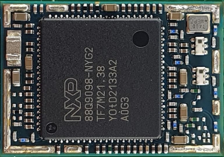
Click to zoom
Application Details
- Equipment Class
- NII - Unlicensed National Information Infrastructure TX
- Date of Grant
- Dec 01, 2022
- Application Purpose
- Original Equipment
- Date of Application
- Nov 30, 2022
- Equipment Note
- JODY-W374-00A and JODY-W374-00B
- Frequency Range
- 5745.00000000 - 5825.00000000
- Company
- u-blox AG
- Country
- Switzerland
Documents & Files
Document Text
Text extracted from the exhibit documents filed with the FCC. Open a document above to read the original.
Users Manual
UBX-19011209 - R07 C2-Restricted www.u-blox.com JODY-W3 series Host-based modules with Wi-Fi 6 and Bluetooth 5.3 System integration manual Abstract This document describes the system integration of JODY-W3 series modules. These host-based modules support concurrent dual-band Wi-Fi 802.11n/ac/ax and Bluetooth® 5.3 and are designed for both simultaneous and independent operations. JODY-W3 modules include an integrated MAC/baseband processor and RF front-end components of automotive grade. JODY-W3 series - System integration manual UBX-19011209 - R07 Document information Page 2 of 71 C2-Restricted Document information Title JODY-W3 series Subtitle Host-based modules with Wi-Fi 6 and Bluetooth 5.3 Document type System integration manual Document number UBX-19011209 Revision and date R07 8-Aug-2022 Disclosure Restriction C2-Restricted Product status Corresponding content status Functional Sample Draft For functional testing. Revised and supplementary data will be published later. In Development / Prototype Objective Specification Target values. Revised and supplementary data will be published later. Engineering Sample Advance Information Data based on early testing. Revised and supplementary data will be published later. Initial Production Early Production Information Data from product verification. Revised and supplementary data may be published later. Mass Production / End of Life Production Information Document contains the final product specification. This document applies to the following products: Product name JODY-W354-A JODY-W374-A JODY-W374 JODY-W377-A JODY-W377 ☞ For information about the related hardware, software, and status of listed product types, see the JODY-W3 series data sheet [1]. u-blox or third parties may hold intellectual property rights in the products, names, logos and designs included in this document. Copying, reproduction, modification or disclosure to third parties of this document or any part thereof is only permitted with the express written permission of u-blox. The information contained herein is provided “as is” and u-blox assumes no liability for its use. No warranty, either express or implied, is given, including but not limited to, with respect to the accuracy, correctness, reliability and fitness for a particular purpose of the information. This document may be revised by u-blox at any time without notice. For the most recent documents, visit www.u-blox.com. Copyright © u-blox AG. u-blox or third parties may hold intellectual property rights in the products, names, logos and designs included in this document. Copying, reproduction, modification or disclosure to third parties of this document or any part thereof is only permitted with the express written permission of u-blox. The information contained herein is provided “as is” and u-blox assumes no liability for its use. No warranty, either express or implied, is given, including but not limited to, with respect to the accuracy, correctness, reliability and fitness for a particular purpose of the information. This document may be revised by u-blox at any time without notice. For the most recent documents, visit www.u-blox.com. Copyright © u-blox AG. JODY-W3 series - System integration manual UBX-19011209 - R07 Contents Page 3 of 71 C2-Restricted Contents Document information ................................................................................................................................ 2 Contents .......................................................................................................................................................... 3 1 System description ............................................................................................................................... 6 1.1 Overview ........................................................................................................................................................ 6 1.1.1 Module architecture ........................................................................................................................... 6 1.1.2 Radio interfaces .................................................................................................................................. 7 1.1.3 Power management ........................................................................................................................... 7 1.2 Pin configuration and function ................................................................................................................. 8 1.2.1 Pin attributes ....................................................................................................................................... 8 1.2.2 Pin list .................................................................................................................................................... 9 1.3 Supply interfaces ......................................................................................................................................12 1.3.1 Main supply inputs ...........................................................................................................................12 1.3.2 Regulated DC power supply ............................................................................................................13 1.4 System function interfaces ....................................................................................................................13 1.4.1 Power-up sequence ..........................................................................................................................13 1.4.2 Reset ...................................................................................................................................................14 1.4.3 Power-off sequence ..........................................................................................................................14 1.4.4 Wake-up signals ...............................................…
Text truncated - open the document above for the full version.
Block Diagram
locate, communicate, accelerate RE: Certification Application Product family: JODY-W3 Models: JODY-W354, JODY-W374, JODY-W377 Block Diagram of the JODY-W3 series modules Figure 1: Block diagram of JODY-W354 and JODY-W374 Registered office: u-blox AG Zürcherstrasse 68 8800 Thalwil Switzerland Company number: CH-020.3.020.161-7 [email protected] [email protected] Figure 2: Block diagram of JODY-W377
Cover Letter(s)
THIS MUST BE SIGNED BY THE APPLICANT/AGENT AND SHOULD BE PLACED ONAPPROPRIATELETTERHEAD 070920-02b Request forModular/Limited Modular Approval Date:September 9, 2022 Subject:Manufacturer’s Declaration for☒-Modular Approval☐-SplitModular Approval ☐-Limited Modular Approval☐-Limited SplitModular Approval Confidentiality Request for:XPYJODY374 8 Basic Requirements–FCC Part 15.212(a)(1) For Items Marked “NO(*)”, the Limited Module Description Must be Filled Out on the Following Pages Modular Approval RequirementRequirement Met 1.The modular transmitter must haveits own RF shielding. This is intended to ensure that the module does not have to rely upon the shielding provided by the device into which it is installed in order for all modular transmitter emissions tocomply with FCC limits. It is also intended to prevent coupling between the RF circuitry of the module and any wires or circuits in the device into which the module is installed. Such coupling may result in non-compliant operation. The physical crystal and tuning capacitors may be located external to the shielded radio elements. 15.212(a)(1)(i) ☒-YES☐-NO(*) Details: <example–The module contains a metal shield which covers all RF components and circuitry. The shield is located on the topof the board next to antenna connector> 2.The modular transmitter must havebuffered modulation/data inputs(if such inputs are provided) to ensure that the module will comply with FCC requirements under conditions of excessive data rates or over-modulation. 15.212(a)(1)(ii) ☒-YES☐-NO(*) Details: <example–Data to the modulation circuit isbuffered as described in the operational description provided with the application> 3.The modular transmitter must haveits own power supply regulationon the module. This is intended to ensure that the module will comply with FCC requirements regardless of the design of the power supplying circuitry in the device into which the module is installed. 15.212(a)(1)(iii) ☒-YES☐-NO(*) Details: <example–The module contains its own power supply regulation. Please refer to schematic filed with this application> 4.The modular transmitter mustcomply with the antenna and transmission system requirementsof §§ 15.203, 15.204(b), 15.204(c), 15.212(a), and 2.929(b). The antenna must either be permanently attached or employ a ‘‘unique’’ antenna coupler (at all connections between the module and the antenna, including the cable). The ‘‘professional installation’’ provision of § 15.203 is not applicable to modules but can apply to limited modular approvals under paragraph 15.212(b). 15.212(a)(1)(iv) ☒-YES☐-NO(*) Details: <example–The module connects to its antenna using an UFL connector which is considered a non-standard connector. A list of antennas tested and approved with this device may be found in users manual provided with the application> 5.The modular transmitter must betested in a stand-alone configuration, i.e., the module must not be inside another device during testing. This is intended to demonstrate that the module is capable of complying with Part 15 emission limits regardless of thedevice into which it is eventually installed. Unless the transmitter module will be battery powered, it must comply with the AC line conducted requirements found in Section 15.207. AC or DC power lines and data input/output lines connected to the modulemust not contain ferrites, unless they will be marketed with the module (see Section 15.27(a)). The length of these lines shall be length typical of actual use or, if that length is unknown, at least 10 centimeters to insure that there is no coupling between the case of the module and supporting equipment. Any accessories, peripherals, or support equipment connected to the module during testing shall be unmodified or commercially available (see Section 15.31(i)). 15.212(a)(1)(v) ☒-YES☐-NO(*) Details: <example–The module was tested stand-alone as shown in test setup photographs filed with this application> THIS MUST BE SIGNED BY THE APPLICANT/AGENT AND SHOULD BE PLACED ONAPPROPRIATELETTERHEAD 070920-02b Modular Approval RequirementRequirement Met 6.The modular transmitter must belabeled with its own FCC ID number, or use an electron display (see KDB Publication 784748). If using a permanently affixed label with its own FCC ID number, if the FCC ID is not visible when the module is installed inside another device, then the outside of the device into which the module is installed must also display a label referring to the enclosed module. This exterior label can use wording such as the following: “Contains Transmitter Module FCC ID: XYZMODEL1” or “Contains FCC ID: XYZMODEL1.” Any similar wording that expresses thesame meaning may be used. The Grantee may either provide such a label, an example of which must be included in the application for equipment authorization, or, must provide adequate instructions along with the module which explain this requirement. In thelatter case, a copy of these instructions must be included in the application for equipment authorization. If the modular transmitter uses an electronic display of the FCC identification number, the information must be readily accessible and visible on the modular transmitter or on the device in which it is installed. If the module is installed inside another device, then the outside of the device into which the module is installed must display a label referring to the enclosed module. This exterior labelcan use wording such as the following: “Contains FCC certified transmitter module(s).” Any similar wording that expresses the same meaning may be used. The user manual must include instructions on how to access the electronic display. A copy of these instructions must be included in the application for equipment authorization. 15.212(a)(1)(vi) ☒-YES☐-NO(*) Details: <example–There is a label on the module as shown in the labeling exhibit filed with this application. Host specific labeling instructions are shown in the installation manual .filed…
Text truncated - open the document above for the full version.
Cover Letter(s)
Attn: Director of Certification Federal Communications Commission 7435 Oakland Mills Road Columbia, MD 21046 Authority to Act as Agent Model / HVIN: JODY-W374-00A, JODY-W374-00B PMN: JODY-W374-00A, JODY-W374-00B FCC ID: XPYJODYW374 IC: 8595A-JODYW374 To whom it may concern: 7Layers GmbH is authorized to act on our behalf, until otherwise notified, for applications to American Certification Body, Inc. (ACB). We certify that we are not subject to denial of federal benefits, that includes FCC benefits, pursuant to Section 5301 of the Anti-Drug Abuse Act of 1988, 21 U.S.C. 862. Further, no party, as defined in 47 CFR 1.2002 (b), to the application is subject to denial of federal benefits, that includes FCC benefits. We also declare that the information provided to the FCC is true and correct to the best of our knowledge (47 CFR 2.911(d)) and we have been informed of the grantee responsibilities (47 CFR 2.909) with regard to certified equipment. Thank you, Agency Agreement Expiration Date: 08/22/2023 Sincerely, Applicant’s Company: u-blox AG Address: Zürcher Strasse 68, CH-8800 Thalwil, Switzerland _______________________________ Filip Kruzela Job Title and Dept.: Certification Manager Registered office: u-blox AG Zürcherstrasse 68 8800 Thalwil Switzerland Company number: CH-020.3.020.161-7 [email protected] [email protected]
Cover Letter(s)
Attn: Reviewing Engineer Federal Communications Commission 7435 Oakland Mills Road Columbia, MD 21046 RE: Certification Application Model / HVIN: JODY-W374-00A, JODY-W374-00B PMN: JODY-W374-00A, JODY-W374-00B FCC ID: XPYJODYW374 IC: 8595A-JODYW374 Request for Long/Short-term Confidentiality To whom it may concern: Pursuant to sections 0.457(d) and 0.459 of CFR 47 and to avoid premature release of sensitive information prior to marketing or release of the product to the public, we hereby requests long-term confidential treatment of information accompanying this application as outlined below: Schematics Software security and software configuration description incl. software configuration control declaration Block Diagram Detailed Operational Description In addition we hereby request the following exhibits contained in this application to be temporarily (short-term confidentiality) withheld from the public disclosure for an initial period of days until: not applicable External Photos Test Setup Photos Internal Photos User’s Manual The above materials contain trade secrets and proprietary information not customarily released to the public. The public disclosure of these matters might be harmful to the applicant and provide unjustified benefits to its competitors. The applicant understands that pursuant to rule 0.457(d), disclosure of this application and all accompanying documentation will not be made before the date of the GRANT for this application. Thank you for your attention in this matter. Please contact the one signed below or the authorized agent for this filing. Thank you. Applicant’s Company: u-blox AG Address: Zürcher Strasse 68, CH-8800 Thalwil, Switzerland _______________________________ Filip Kruzela Job Title and Dept.: Certification Manager Registered office: u-blox AG Zürcherstrasse 68 8800 Thalwil Switzerland Company number: CH-020.3.020.161-7 [email protected] [email protected]
External Photos
JODY-W3 photos UBXDOC-885269510-17923 Page 1 of 3 JODY-W3 photos Topic : JODY-W3 photos Doc.No: UBXDOC-885269510-17923 Revision R01 Date: Name Signature Created 19-Aug-2022 Franck Campagna frca Checked Released 22-Aug-2022 Franck Campagna frca We reserve all rights in this document and in the information contained therein. Reproduction, use or disclosure to third parties without express authority is strictly forbidden. © 20168 u-blox AG 1 Scope This document provides internal and external photos of the JODY-W3 family modules. It is part of the equipment certification application issued to FCC and ISED. The photos have been taken with the RF shield mounted and removed. 2 FCC/IC ID reference Ordering Code(s) FCC ID ISED ID JODY-W374-00A JODY-W374-00B JODY-W377-00A JODY-W377-00B XPYJODY-W374 XPYJODY-W374 XPYJODY-W377 XPYJODY-W377 8595A-JODYW374 8595A-JODYW374 8595A-JODYW377 8595A-JODYW377 Table 1: FCC and IC IDs for different models of JODY-W3 series JODY-W3 photos UBXDOC-885269510-17923 Page 2 of 3 3 Top view 3.1 Internal photos Figure 1: JODY-W374-00A and JODY-W374-00B internal photo Figure 2: JODY-W377-00A and JODY-W377-00B internal photo JODY-W3 photos UBXDOC-885269510-17923 Page 3 of 3 3.2 External photos Figure 4: JODY-W374-00A top view external photo Figure 5: JODY-W377-00A top view external photo Figure 6: JODY-W374-00B top view external photo Figure 7: JODY-W377-00B top view external photo 4 Bottom view Figure 8: Bottom view of JODY-W37x-00x bottom view
ID Label/Location Info
RE: Certification Application HVIN : JODY-W374-00A, FCC ID : XPYJODYW374, IC : 8595A-JODYW374 HVIN : JODY-W374-00B, FCC ID : XPYJODYW374, IC : 8595A-JODYW374 HVIN : JODY-W377-00A, FCC ID : XPYJODYW377, IC : 8595A-JODYW377 HVIN : JODY-W377-00B, FCC ID : XPYJODYW377, IC : 8595A-JODYW377 Label location information for JODY-W3 series modules The product label is affixed on to the module shield cover as shown in Figure 1. The size of the label is 17 x 11 mm and contains the following information: • A Data Matrix formatted bar code, with a unique serial number • Date of unit production formatted YY/WW (year/week) • Major and minor product version info • Product marketing name (e.g. JODY-W374-00A, JODY-W374-00B, JODY-W377-00A, JODY- W377-00B) Figure 1: Label of the JODY-W374-00A module Figure 2: Label of the JODY-W374-00B module Registered office: u-blox AG Zürcherstrasse 68 8800 Thalwil Switzerland Company number: CH-020.3.020.161-7 [email protected] [email protected] Figure 3: Label of the JODY-W377-00A module Figure 4: Label of the JODY-W377-00b module Figure 2: Actual size of the JODY-W3 modules identifier marking (17 x 11 mm) Figure 3: Label location of the JODY-W3 modules
Internal Photos
JODY-W3 photos UBXDOC-885269510-17923 Page 1 of 3 JODY-W3 photos Topic : JODY-W3 photos Doc.No: UBXDOC-885269510-17923 Revision R01 Date: Name Signature Created 19-Aug-2022 Franck Campagna frca Checked Released 22-Aug-2022 Franck Campagna frca We reserve all rights in this document and in the information contained therein. Reproduction, use or disclosure to third parties without express authority is strictly forbidden. © 20168 u-blox AG 1 Scope This document provides internal and external photos of the JODY-W3 family modules. It is part of the equipment certification application issued to FCC and ISED. The photos have been taken with the RF shield mounted and removed. 2 FCC/IC ID reference Ordering Code(s) FCC ID ISED ID JODY-W374-00A JODY-W374-00B JODY-W377-00A JODY-W377-00B XPYJODY-W374 XPYJODY-W374 XPYJODY-W377 XPYJODY-W377 8595A-JODYW374 8595A-JODYW374 8595A-JODYW377 8595A-JODYW377 Table 1: FCC and IC IDs for different models of JODY-W3 series JODY-W3 photos UBXDOC-885269510-17923 Page 2 of 3 3 Top view 3.1 Internal photos Figure 1: JODY-W374-00A and JODY-W374-00B internal photo Figure 2: JODY-W377-00A and JODY-W377-00B internal photo JODY-W3 photos UBXDOC-885269510-17923 Page 3 of 3 3.2 External photos Figure 4: JODY-W374-00A top view external photo Figure 5: JODY-W377-00A top view external photo Figure 6: JODY-W374-00B top view external photo Figure 7: JODY-W377-00B top view external photo 4 Bottom view Figure 8: Bottom view of JODY-W37x-00x bottom view
RF Exposure Info
7layers GmbH,Melanie Anastassiou, Project Manager,29/11/2022 MDE_UBLOX_2030_MPE_03 RF Exposure evaluation Page1|4 Applicant Data:u-blox AG Zürcher Strasse 68 8809 Thalwil Switzerland Product Data:description:Host-based automotive module with Wi-Fi andBluetooth product:JODY-W377-00A; JODY-W377-00B JODY-W374-00A;JODY-W374-00B trademark:u-blox supported Technologies:Bluetooth Classic, Bluetooth Low Energy, WLAN 2,4 GHz and WLAN 5 GHz device category:mobile device environment:General Population/Uncontrolled FCC ID:XPYJODYW377 XPYJODYW374 IC:8595A-JODYW377 8595A-JODYW374 Standards OET Bulletin 65 Edition 97-01 August 1997 RSS-102 Issue 5–March 2015 ------------------------------------------------------------------------- FCC CFR 47, Part 2.1091:Radiofrequency radiation exposure evaluation: mobile devices. FCC CFR 47, Part 2.1307:Actions that may have a significant environmental effect, forwhich Environmental Assessments (EAs) must be prepared. FCC CFR 47, Part 2.1310:Radiofrequency radiation exposure limits. 7layers GmbH,Melanie Anastassiou, Project Manager,29/11/2022 MDE_UBLOX_2030_MPE_03 RF Exposure evaluation Page2|4 Maximum Permissible Exposure As specified inChapter e(1)of 47 CFRPart1.1310–Limits for Maximum Permissible Exposure (MPE) Table(ii)–Limits forGeneral Population/ Uncontrolled Exposure Frequency range (MHz)Power density (mW/cm²) 300–1500f/1500 1500-1000001.0 As specified inChapter 4ofRSS-102, Issue 5–Exposure Limits Table 4-RF Field StrengthLimits for Devices Used by the General Public (Uncontrolled Environment) Frequency range (MHz)Power density (W/m²)Power density (mW/cm²) 300-60000.02619 f 0.6834 mW/cm²=W/m²*0.1 6000-150000101.0 7layers GmbH,Melanie Anastassiou, Project Manager,29/11/2022 MDE_UBLOX_2030_MPE_03 RF Exposure evaluation Page3|4 Calculations Equation OET bulletin 65, page 18,edition 97-01:S = P * G / ( 4**R² ) R =√ (P * G / S lim *4 *) G =S lim * 4 **R² / P Where: S = power density(mW/cm²) P = power input to the antenna(mW) G = power gain of the antenna(mW) R = distance to thecentreofradiation of the antenna(cm) S lim = FCC / IC Limit(mW/cm²) Simultaneous Transmission Considerations The calculation belowis used to consider situations in which simultaneous exposure to fields of different frequencies occur. The calculation is performed by the sum of each relative exposure for each equipment according to the following criteria. Where: S eq = S = power density (mW/cm²) S lim =FCC / ICLimit (mW/cm²) 7layers GmbH,Melanie Anastassiou, Project Manager,29/11/2022 MDE_UBLOX_2030_MPE_03 RF Exposure evaluation Page4|4 Assessment With: G =2dBi R =20cm Simultaneous: 1 st Technology e.g. Bluetooth Classic (BT) 2 nd Technology WLAN 2,4 GHz (WLAN24) 3 rd Technology WLAN 5 GHz (WLAN5) (S eq / S lim ) 0.00500.06290.0315 Sum of (S eq / S lim ) BT+WLAN24+WLAN5 0.0994 Limit 1.0000 Conclusion passed Note 1: only worst-case values are listed in the tablesabove Note 2: the duty cycle correction factor is already included in themeasurement values GPP*GSSlimSeq/Slim Operational Bands Antenna Gain (dBi) Antenna Gain -numeric- (mW) Tune Up (dBm) Output Power -conducted- (dBm) Output Power -conducted- (mW) Output power (EIRP) (dBm) Output Power (EIRP) (mW) Power Density value (mW/cm²) FCC Limit (mW/cm²) Relative Power Density value Margin to FCC Limit (mW/cm²) Bluetooth 21,5849 1,0011,00 15,8513,0019,950,00501,00000,00500,9950 Bluetooth LE 21,5849 1,009,00 10,0011,0012,590,00321,00000,00320,9968 802.11b 21,5849 2,0021,00 199,5323,00199,530,06291,00000,06290,9371 802.11g 21,5849 2,0018,00 100,0020,00100,000,03151,00000,03150,9685 802.11n_HT 20 21,5849 2,0017,00 79,4319,0079,430,02501,00000,02500,9750 802.11n_HT 40 21,5849 2,0013,00 31,6215,0031,620,01001,00000,01000,9900 802.11ax _HT 20 21,5849 2,0017,00 79,4319,0079,430,02501,00000,02500,9750 802.11ax _HT 40 21,5849 2,0013,00 31,6215,0031,620,01001,00000,01000,9900 802.11a 21,5849 2,0018,00 100,0020,00100,000,03151,00000,03150,9685 802.11n 20M 21,5849 2,0017,00 79,4319,0079,430,02501,00000,02500,9750 802.11n 40M 21,5849 2,0016,00 63,1018,0063,100,01991,00000,01990,9801 802.11ac 20M 21,5849 2,0017,00 79,4319,0079,430,02501,00000,02500,9750 802.11ac 40M 21,5849 2,0016,00 63,1018,0063,100,01991,00000,01990,9801 802.11ac 80M 21,5849 2,0016,00 63,1018,0063,100,01991,00000,01990,9801 802.11ax 20M 21,5849 2,0015,00 50,1217,0050,120,01581,00000,01580,9842 802.11ax 40M 21,5849 2,0015,00 50,1217,0050,120,01581,00000,01580,9842 802.11ax 80M 21,5849 2,0015,00 50,1217,0050,120,01581,00000,01580,9842
Test Report
PRODUCT FACTS: • External chassis mount antenna • Dual band dipole antenna • RoHS compliant SPECIFICATIONS: • Frequency Range: – 2400-2500 MHz; 5150-5875 MHz • Peak Gain: – 2.0 dBi @ 2400-2500 MHz – 2.0 dBi @ 5150-5875 MHz • VSWR: <2.0:1 • Return Loss: <-10.0 dB • Azimuth Beam Width: Omni directional • Feed Point Impedance: 50 ohms • Power Handling: 10 Watt cw • Size: 108 x 10 mm • Weight: 8.5g • Connector: RP-SMA • Operating Temperature: -30° to 75°C 2400-2500 & 5150-5875 MHz DUAL BAND ANTENNA Standard Antenna Solutions 802.11 a/b/g/n, Wi-Fi 4-6, includes frequencies of Bluetooth, ZigBee, and Wi-Fi products Part Number: 2195630-1 AZIMUTH:ELEVATION: RETURN LOSS:VSWR: EFFICIENCY: TEST ORIENTATION IN FREE SPACE: DATA AND DEVICES /// 2400-2500 & 5150-5875 MHz DUAL BAND ANTENNA DATA AND DEVICES /// 2400-2500 & 5150-5875 MHz DUAL BAND ANTENNA 2400-2500 & 5150-5875 MHz Dual Band Antenna Standard Antenna Solutions te.com TE Connectivity, TE Connectivity (logo) and Every Connection Counts are trademarks. All other logos, products and/or company names referred to herein might be trademarks of their respective owners. The information given herein, including drawings, illustrations and schematics which are intended for illustration purposes only, is believed to be reliable. However, TE Connectivity makes no warranties as to its accuracy or completeness and disclaims any liability in connection with its use. TE Connectivity‘s obligations shall only be as set forth in TE Connectivity‘s Standard Terms and Conditions of Sale for this product and in no case will TE Connectivity be liable for any incidental, indirect or consequential damages arising out of the sale, resale, use or misuse of the product. Users of TE Connectivity products should make their own evaluation to determine the suitability of each such product for the specific application. © 2019 TE Connectivity Ltd. family of companies All Rights Reserved. 1-1773975-4 05/19 Original TE TECHNICAL SUPPORT CENTER USA: +1 (800) 522-6752 Canada: +1 (905) 475-6222 Mexico: +52 (0) 55-1106-0800 Latin/S. America +54 (0) 11-4733-2200 Germany: +49 (0) 6251-133-1999 UK: +44 (0) 800-267666 Fr ance: +33 (0) 1-3420-8686 Netherlands: +31 (0) 73-6246-999 China: +86 (0) 400-820-6015 For phone numbers in other countries, go to te.com/support-center DIMENSIONS:
Test Report
DATA AND DEVICES / 001-0009 001-0009 Dipole Antenna 2400-2500 MHz/4910-5850 MHz ELECTRICAL SPECIFICATION Model Name001-0009 Operating Frequency (MHz)2400-25005150-5850 VSWR – max≤ 2.0:1 Gain (dBi)2.02.0 Nominal Impedance (Ohms)50 PolarizationLinear vertical MECHANICAL SPECIFICATION Dimensions – mm (inches)137 x 13 (5.4 x 0.51) Weight – g (oz.)22.0 (0.78) Radome MaterialBlack ENVIRONMENTAL SPECIFICATION Operating Temperature – °C (°F)-40 to +85°C (-40 to +185°F) UL RatingUL 94HB PART NUMBERDESCRIPTION 001-00092.4/5.5 GHz dipole antenna for Reverse Polarity SMA connector 080-0001U.FL to Reverse Polarity SMA cable, 105 mm CONFIGURATION 2DATA AND DEVICES / 001-0009 TYPICAL ANTENNA REFLECTION PERFORMANCE MECHANICAL DRAWING te.com TE Connectivity, TE Connectivity (logo) and Every Connection Counts are trademarks. All other logos, products and/or company names referred to herein might be trademarks of their respective owners. The information given herein, including drawings, illustrations and schematics which are intended for illustration purposes only, is believed to be reliable. However, TE Connectivity makes no warranties as to its accuracy or completeness and disclaims any liability in connection with its use. TE Connectivity‘s obligations shall only be as set forth in TE Connectivity‘s Standard Terms and Conditions of Sale for this product and in no case will TE Connectivity be liable for any incidental, indirect or consequential damages arising out of the sale, resale, use or misuse of the product. Users of TE Connectivity products should make their own evaluation to determine the suitability of each such product for the specific application. TE warrants to the original end user customer of its products that its products are free from defects in material and workmanship. Subject to conditions and limitations TE will, at its option, either repair or replace any part of its products that prove defective because of improper workmanship or materials. This limited warranty is in force for the useful lifetime of the original end product into which the TE product is installed. Useful lifetime of the original end product may vary but is not to exceed five (5) years from the original date of the end product purchase. ©2021 TE Connectivity. All Rights Reserved. 10/21 Original USA: +1 (800) 522-6752 Canada: +1 (905) 475-6222 Mexico: +52 (0) 55-1106-0800 Latin/S. America: +54 (0) 11-4733-2200 Germany: +49 (0) 6251-133-1999 UK: +44 (0) 800-267666 France: +33 (0) 1-3420-8686 Netherlands: +31 (0) 73-6246-999 China: +86 (0) 400-820-6015 TE TECHNICAL SUPPORT CENTER DATA AND DEVICES / 001-0009 RADIATION PATTERNS
Test Report
DATA AND DEVICES / 001-0012 001-0012 Waterproof Dipole Antenna 2400-2500 MHz/4910-5850 MHz ELECTRICAL SPECIFICATION Model Name001-0012 Operating Frequency (MHz)2400-25004910-5850 VSWR – max≤ 2.5:1 Gain (dBi)2.02.0 Nominal Impedance (Ohms)50 PolarizationLinear vertical MECHANICAL SPECIFICATION Dimensions – mm (inches)114.0 x 13.0 (4.94 x 0.51) Weight – g (oz.)18.0 (0.63) Radome MaterialBlack ENVIRONMENTAL SPECIFICATION Operating Temperature – °C (°F)-40 to +85°C (-40 to +185°F) UL RatingUL 94HB Ingress Protection RatingIP67 PART NUMBERDESCRIPTION 001-00122.4/5.5 GHz waterproof dipole antenna for Reverse Polarity SMA connector 080-0013U.FL to Reverse Polarity SMA cable, 105 mm, O-ring seal 080…
Text truncated - open the document above for the full version.
Contact Information
Applicant
Giulio Comar(Certification Manager)
Technical Contact
Test Firm
7layers GmbHBernhard Retka
Technical Specifications
| # | Rule Parts | Frequency Range | Power Output |
|---|---|---|---|
| 4 | 15E | 5.75 GHz - 5.83 GHz | 91.20 mW |
Other Applications from u-blox AG
XPYJODYB1
Aug 07, 2026BT Module
Equipment Class
DSS - Part 15 Spread Spectrum Transmitter
XPYMAYAW3A
Feb 01, 2026WLAN and Bluetooth module
Equipment Class
6XD - 15E 6 GHz Low Power Indoor Client
XPYJODYW6A
Jan 22, 2026WLAN and Bluetooth module
Equipment Class
NII - Unlicensed National Information Infrastructure TXXPYUBX22VA03
Jul 22, 2024NB CatM EGPRS data only module
Equipment Class
PCB - PCS Licensed Transmitter
XPYIRISW1
Jul 21, 2024Stand-alone Tri-radio wireless MCU module
Equipment Class
DTS - Digital Transmission System