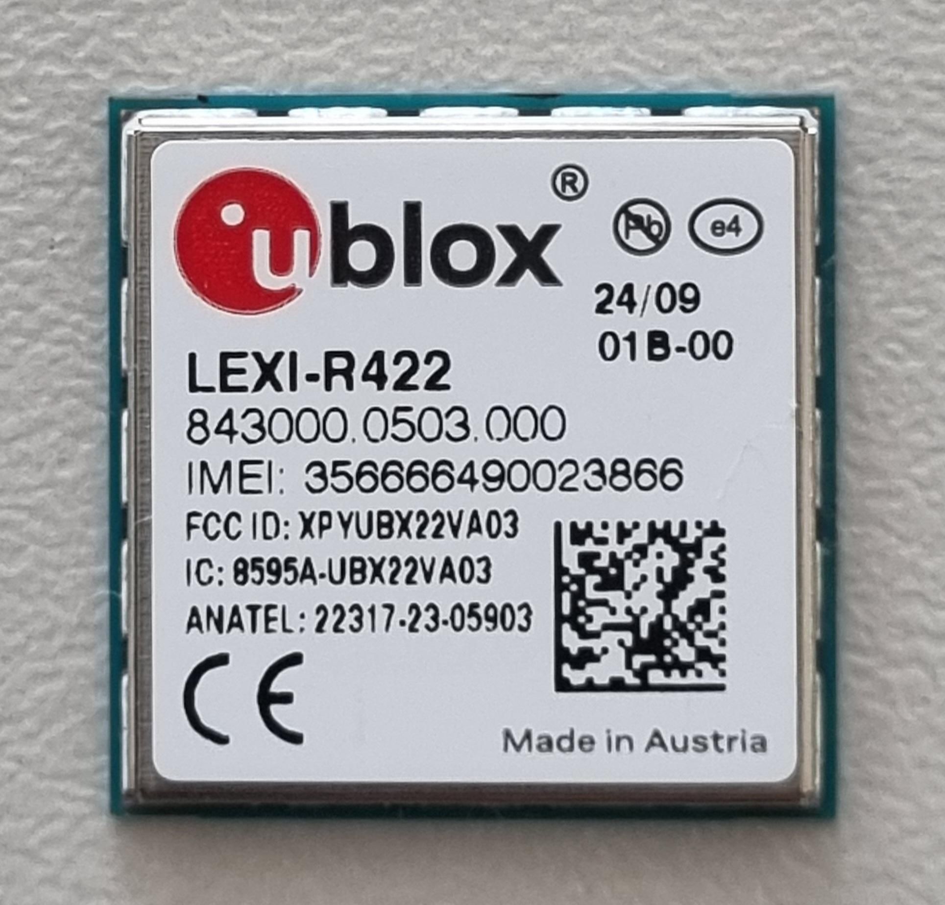
XPYUBX22VA03NB CatM EGPRS data only module
u-blox AGApplication Details
- Equipment Class
- PCB - PCS Licensed Transmitter
- Date of Grant
- Jul 22, 2024
- Application Purpose
- Original Equipment
- Date of Application
- Jul 22, 2024
- Equipment Note
- NB CatM EGPRS data only module
- Frequency Range
- 819.00000000 - 819.00000000
- Company
- u-blox AG
- Country
- Switzerland
Documents & Files
Document Text
Text extracted from the exhibit documents filed with the FCC. Open a document above to read the original.
Attestation Statements
UBXDOC-51455665-28016 - R01 U.S. Agent Designation 1/ 2 C1-Public U.S. Agent Designation Applicant name: u-blox AG Address: Zuercherstrasse 68, CH-8800 Thalwil, Switzerland Info: www.u-blox.com Subject: U.S. Agent Designation To: Federal Communications Commission - Authorization and Evaluation Division Equipment Authorization Branch Address: 7435 Oakland Mills Road Columbia, MD 21046 u-blox AG, as applicant, acknowledges their consent for the following contact located in the United States to act as their agent for service of process for all applications for which authorization is sought (FCC ID: XPYUBX22VA03; FRN: 0019077858): Name and company of U.S. agent: Dave Carey, u-blox San Diego, Inc. Physical U.S. address of agent: 12626 High Bluff Drive Suite 200 San Diego, CA 92130 FRN of U.S. agent: 0022185367 Email address of U.S. agent: [email protected] u-blox San Diego, Inc acknowledges their obligation to accept service of process on behalf of u-blox AG. u-blox AG accepts its obligation to maintain an agent for service of process in the United States for no less than one year after either the grantee has permanently terminated all marketing and importation of the applicable equipment within the U.S., or the conclusion of any Commission-related administrative or judicial proceeding involving the equipment, whichever is later. By signing this form, we confirm the above and that we are aware of the application requirements listed under § 2.911(d)(7). The information provided in this letter is based on the referenced rule parts of Title 47 of the CFR as well as KDB 986446 D01.An expiration date for this letter does not exist. Sincerely, UBXDOC-51455665-28016 - R01 U.S. Agent Designation 2/ 2 C1-Public Signed for and on behalf of u-blox AG : Name Giulio Comar Position Certification Manager Date of issue 15 April 2024 Signature Signed for and on behalf of u-blox San Diego, Inc. : Name Dave Carey Position Senior Vice President Date of issue 15 April 2024 Signature
Cover Letter(s)
Federal Communications Commission Authorization and Evaluation Division Equipment Authorization Branch 7435 Oakland Mills Road Columbia, MD 21046 4/15/2024 To whom it may concern: We, the undersigned, hereby authorize Eurofins Product Service GmbH to act on our behalf in all matters relating to applications for equipment authorization FCC ID: XPYUBX22VA03 including the signing of all documents related to these matters. Any and all acts carried out by Eurofins Product Service GmbH on our behalf shall have the same effect as acts of our own. By signing this application form, we agree to Eurofins’ current valid General Terms and Conditions (AGB),Testing and Certification Regulations (PZO) which can be viewed on following website www.eurofins.de/ee or retrieved on request. We also hereby certify that no party to this application is subject to a denial of benefits, including FCC benefits, pursuant to Section 5301 of the Anti-Drug Abuse Act of 1988, 21 U.S.C. 862. Sincerely, _______________________ Signature Giulio Comar Certification Manager u-blox AG Address: Zurcherstrasse 68, CH-8800 Thalwil, Switzerland
Cover Letter(s)
Author Davide Zorzetto Department: cert Page: 1/2 Filename LEXI-R422SARA-R422_TCB Request for FCC Confidentiality.docx M102 Rev. 1 Copyright © 2024 u-blox AG, All rights reserved Confidential Certification Declaration Rev.: 1.0 Date: 18/03/2024 TCB Request for Confidentiality Issued by: u-blox AG Zürcherstrasse 68 CH-8800 Thalwil / Switzerland Phone: +41 44 722 74 44 Fax: +41 44 722 74 47 [email protected] Receiver: Eurofins Product Service GmbH Storkower Str. 38c 15526 Reichenwalde Germany Subject: Confidentiality Request for: • FCC: XPYUBX22VA03 • Model Name: LEXI-R422 Pursuant to FCC 47 CRF 0.457(d) and 0.459 of the Commission Rules, the applicant requests that a part of the subject FCC application be held confidential. Type of Confidentiality Requested Exhibit Short Term Permanent Block Diagrams Short Term External Photos Short Term Internal Photos Short Term Permanent Operation Description/Theory of Operation Short Term Permanent Parts List & Placement/BOM Short Term Permanent Tune-Up Procedure Short Term Permanent Schematics Short Term Test Setup Photos Short Term User’s Manual u-blox AG, Zuercherstrasse 68, 8800 Thalwil, Switzerland has spent substantial effort in developing this product and it is one of the first of its kind in industry. Having the subject information easily available to "competition" would negate the advantage they have achieved by developing this product. Not protecting the details of the design will result in financial hardship. Author Davide Zorzetto Department: cert Page: 2/2 Filename LEXI-R422SARA-R422_TCB Request for FCC Confidentiality.docx M102 Rev. 1 Copyright © 2024 u-blox AG, All rights reserved Confidential Certification Declaration Rev.: 1.0 Date: 18/03/2024 Permanent Confidentiality: The applicant requests the exhibits listed above as permanently confidential be permanently withheld from public review due to materials that contain trade secrets and proprietary information not customarily released to the public. Short-Term Confidentiality: The applicant requests the exhibits selected above as short term confidential be withheld from public view for a period of 180 days from the date of the Grant of Equipment Authorization and prior to marketing. This is to avoid premature release of sensitive information prior to marketing or release of the product to the public. Applicant is also aware that they are responsible to notify EUROFINS in the event information regarding the product or the product is made available to the public. EUROFINS will then release the documents listed above for public disclosure pursuant to FCC Public Notice DA 04-1705. NOTE for Industry Canada Applications: The applicant understands that until such time that IC distinguishes between Short Term and Permanent Confidentiality, either type of marked exhibit above will simply be marked Confidential when submitted to IC ___________________________________________________ Giulio Comar, Certification Manager Via di Stazione di Prosecco, 15 34010 Sgonico, TRIESTE ITALY
Cover Letter(s)
Modular Approval Request Letter Date: 2024-04-15 FCC ID: XPYUBX22VA03 Type of Equipment: LTE NB2, Cat M1, 2G data only module Herewith we state that the requirements according to FCC Part 15.212 are met and the module qualifies for a single modular transmitter approval. # Requirement as per 47 CFR Part 15 Subpart C §15.212 Conditions met? (Y/N) Realisation / Evidence in FORM 731 application filing i RF shielding The radio elements of the modular transmitter must have their own shielding. The physical crystal and tuning capacitors may be located external to the shielded radio elements. Y All radio parts are fully shielded ii Buffered modulation/data inputs The modular transmitter must have buffered modulation/data inputs (if such inputs are provided) to ensure that the module will comply with part 15 requirements under conditions of excessive data rates or over-modulation. Y It’s part of the radio chipset implementation iii Power supply regulation The modular transmitter must have its own power supply regulation. Y PSU is integrated in the module, see schematic and block diagram iv Antenna requirements The modular transmitter must comply with the antenna and transmission system requirements of §§15.203, 15.204(b) and 15.204(c). The antenna must either be permanently attached or employ a “unique” antenna coupler (at all connections between the module and the antenna, including the cable). Additional justification and details may be requested – please refer to KDB 996369 Y A default antenna is taken as reference, MPE is calculated in reports v Stand-alone test configuration The modular transmitter must be tested in a stand-alone configuration, i.e., the module must not be inside another device during testing for compliance with part 15 requirements. Unless the transmitter module will be battery powered, it must comply with the AC line conducted requirements found in §15.207. AC or DC power lines and data input/output lines connected to the module must not contain ferrites, unless they will be marketed with the module (see §15.27(a)). The length of these lines shall be the length typical of actual use or, if that length is unknown, at least 10 centimeters to insure that there is no coupling between the case of the module and supporting equipment. Any accessories, peripherals, or support equipment connected to the module during testing shall be unmodified and commercially available (see §15.31(i)). Y Module is solely mounted on his interface: see test report/ test set-up photos vi Labelling The modular transmitter must be equipped with either a permanently affixed label or must be capable of electronically displaying its FCC identification number. Y The module has it’s label, see label example vii Compliance on specific rule or operating requirements The modular transmitter must comply with any specific rules or operating requirements that ordinarily apply to a complete transmitter and the manufacturer must provide adequate instructions along with the module to explain any such requirements. A copy of these instructions must be included in the application for equipment authorization. Y The required FCC rules has been fulfilled and all instructions for maintaining compliance has been clearly stated in the user manual viii RF Exposure Radio frequency devices operating under the provisions of this part are subject to the radio frequency radiation exposure requirements specified in §§1.1307(b), 1.1310, 2.1091, and 2.1093 of this chapter, as appropriate. Applications for equipment authorization of modular transmitters under this section must contain a statement confirming compliance with these requirements. The modular transmitter must comply with any applicable RF exposure requirements in its final configuration. Y RF exposure requirements are fulfilled for mobile configuration. The installation of the module is restricted to mobile host devices what is clearly stated in the installation instruction of the user manual. For portable applications OEM integrators need SAR evaluation and an own FCC ID. Sincerely, _______________________ Signature Giulio Comar Certification Manager u-blox AG Address: Zuercherstrasse 68, CH-8800 Thalwil, Switzerland
RF Exposure Info
Test Laboratory: 7layers GmbH Borsigstraße 11 40880 Ratingen Germany Note: The following test results relate only to the devices specified in this document. This report shall not be reproduced in parts without the written approval of the test laboratory. 7layers GmbH Geschäftsführer / Borsigstraße 11 Managing Directors Registergericht/registered: a Bureau Veritas 40880 Ratingen, Germany Sebastian Doose Düsseldorf HRB 75554 Group Company T +49 (0) 2102 749 0 Stefan Kischka: USt-Id.-Nr./VAT No. DE203159652 F +49 (0) 2102 749 350 Bernhard Retka Steuer-Nr./TAX No. 147/5869/0385 www.7layers.com RF Exposure and Maximum ERP/EIRP Assessment for LEXI-R422 CAT-M1 /NB-IoT Data Modules FCC ID: XPYUBX22VA03 IC: 8595A-UBX22VA03 Assessment Reference: MDE_UBLOX_2308_MPE_02 Assessment Reference: MDE_UBLOX_2308_MPE_02 Page 2 of 10 Table of Contents 0 Summary 3 0.1 Technical Report Summary 3 1 Administrative Data 4 1.1 Testing Laboratory 4 1.2 Project Data 4 1.3 Applicant Data 4 1.4 Manufacturer Data 4 2 Test object Data 5 2.1 General EUT Description 5 2.2 EUT Main components 5 3 Evaluation Results 6 3.1 Maximum ERP / EIRP 6 3.2 RF Exposure Evaluation for Module 8 Assessment Reference: MDE_UBLOX_2308_MPE_02 Page 3 of 10 0 Summary 0.1 Technical Report Summary Type of Report RF Exposure and Maximum ERP/EIRP Assessment for a CAT-M1/NB-IoT radio module. Including RF Exposure for use with co-located radios on generic host device. Applicable FCC and ISED Rules For RF Exposure: OET Bulletin 65 Edition 97-01 August 1997 FCC 47 CFR §1.1307 FCC 47 CFR §1.1310 RSS-102 Issue 6 For Maximum ERP/EIRP: FCC 47 CFR §22.913 ISED RSS-132, Issue 4 FCC 47 CFR §24.232 ISED RSS-133 Issue 6, Amendment 1 FCC 47 CFR §27.50(b), (c), (d) ISED RSS-139, Issue 4 / SRSP-513, RSS-130, Issue 2, ISED RSS-195, Issue 2, ISED RSS-199, Issue 3 FCC 47 CFR §90.635 ISED RSS-140, Issue 1 Report version control Rev Version Release date Changes Version validity - 2024-01-11 Initial version Invalid Responsible for Accreditation Scope: Responsible for Report: Assessment Reference: MDE_UBLOX_2308_MPE_02 Page 4 of 10 1 Administrative Data 1.1 Testing Laboratory Company Name: 7layers GmbH Address Borsigstr. 11 40880 Ratingen Germany FCC accreditation Designation Number: DE0015 Test Firm Registration #: 929146 Industry Canada Test Site Acceptance CAB identifier: DE0007 Test Firm Registration #: 3699A The test facility is also accredited by the following accreditation organisation: Laboratory accreditation no.: DAkkS D-PL-12140-01-01 DAkkS D-PL-12140-01-02 DAkkS D-PL-12140-01-03 Responsible for Accreditation Scope: Dipl.-Ing. Bernhard Retka Dipl.-Ing. Robert Machulec Dipl.-Ing. Andreas Petz Dipl.-Ing. Marco Kullik Report Template Version: 2023-08-02, V19 1.2 Project Data Responsible for assessment and report: Patrick Lomax Date of Report: 2024-01-11 1.3 Applicant Data Company Name: u-blox AG Address: Zürcherstrasse 68, CH-8800 Thalwil Switzerland Contact Person: Giulio Comar 1.4 Manufacturer Data Company Name: please see applicant data Address: Contact Person: Assessment Reference: MDE_UBLOX_2308_MPE_02 Page 5 of 10 2 Test object Data 2.1 General EUT Description Equipment under Test LEXI-R422 Type Designation: LEXI-R422 Kind of Device: LTE CAT-M1 / NB-IoT / GSM/ EGPRS Module GSM MSC/LTE CAT EGPRS MSC33/ CAT-M1 / NB2 FCC ID: XPYUBX22VA03 IC ID: 8595A-UBX22VA03 General product description: The EUTs are Cellular radio modules supporting CAT-M1/NB-IoT and GSM. 2.2 EUT Main components Type, S/N, Short Descriptions etc. used in this Test Report Short Description Equipment under Test Type Designation HW Status SW Status CAT-M1 / NB-IoT Data Modules LEXI-R422 LEXI-R422 UBX-427C00 01.25,A01.11 Remark: EUT is equipped with a temporary antenna connector. The Module is not sold with a predefined antenna. Assessment Reference: MDE_UBLOX_2308_MPE_02 Page 6 of 10 3 Evaluation Results 3.1 Maximum ERP / EIRP Standard Frequency Band FCC 47 CFR §22.913 ISED RSS-132, Issue 4 GSM 850/ eFDD5/ eFDD26 FCC 47 CFR §24.232 ISED RSS-133 Issue 6, Amendment 1 GSM 1900 / eFDD2/ eFDD25 FCC 47 CFR §27.50(d) ISED RSS-139, Issue 4 / SRSP-513 eFDD4/66 FCC 47 CFR §27.50(c) ISED RSS-130, Issue 2 eFDD12 FCC 47 CFR §27.50(b) ISED RSS-130, Issue 2 eFDD13 FCC 47 CFR §90.635 eFDD26 FCC 47 CFR §27.1507(a) eFDD8 3.1.1 Test Limits For the 850MHz band, FCC §22.913 states that the maximum ERP of this device shall not exceed 7 Watts. IC SRSP-503 Issue 7, states that this device shall not exceed a maximum EIRP of 11.5 Watts For the purposes of this test report, the 7 Watt ERP limit stipulated in FCC §22.913 has been converted to an equivalent EIRP value of 11.5 Watts. For all other limits, refer to the values stipulated in the corresponding tables. 3.1.2 Test Protocol Maximum antenna gain to comply with EIRP limits for FCC and Industry Canada Band Mode Duty Cycle Frequency Range (MHZ) Maximum Conducted output power (dBm) Maximum Conducted output power (mW) FCC EIRP limit (mW) Maximum antenna gain to meet EIRP Limit (dBi) 850 GSM 50.0% 824.2 - 848.8 31.94 1563.1476 11484 8.7 1900 GSM 50.0% 1850.2 - 1909.8 29.26 843.33476 2000 3.8 eFDD 2 CAT M 100.0% 1850-1910 22.32 170.60824 2000 10.7 eFDD 4 CAT M 100.0% 1710-1755 22.89 194.53601 1000 7.1 eFDD 5 CAT M 100.0% 824 - 849 22.92 195.88447 11484 17.7 eFDD 12 CAT M 100.0% 699-716 23.25 211.3489 4920 13.7 eFDD 13 CAT M 100.0% 777-787 23.11 204.64446 4920 13.8 eFDD 25 CAT M 100.0% 1850–1915 22.75 188.36491 2000 10.3 eFDD 26 CAT M 100.0% 814–849 23.17 207.49135 11484 17.4 eFDD 66 CAT M 100.0% 1710-1780 23.32 214.78305 1000 6.7 eFDD 8 CAT M 100.0% 898-890 22.96 197.69696 4920 14.0 Assessment Reference: MDE_UBLOX_2308_MPE_02 Page 7 of 10 Maximum antenna gain to comply with EIRP limits for FCC and Industry Canada Band Mode Duty Cycle Frequency Range (MHZ) Maximum Conducted output power (dBm) Maximum Conducted output power (mW) FCC EIRP limit (mW) Maximum antenna gain to meet EIRP Limit (dBi) eFDD 2 NB-IOT 100.0% 1850-1910 21.22 132.43415 2000 11.8 eFDD 4 NB-IOT 100.0% 17…
Text truncated - open the document above for the full version.
Test Report
Test Laboratory: 7layers GmbH Borsigstrasse 11 40880 Ratingen Germany Note: The following test results relate only to the devices specified in this document. This report shall not be reproduced in parts without the written approval of the test laboratory. 7layers GmbH Geschäftsführer/ Borsigstraße 11 Managing Directors: Registergericht/registered: a Bureau Veritas 40880 Ratingen, Germany Sebastian Doose Düsseldorf HRB 75554 Group Company T +49 (0) 2102 749 0 Stefan Kischka USt-Id.-Nr./VAT-No. DE203159652 F +49 (0) 2102 749 350 Bernhard Retka Steuer -Nr./TAX-No. 147/5869/0385 www.7layers.com Commerzbank AG Account No. 303 016 000 Bank Code 300 400 00 IBAN DE81 3004 0000 0303 0160 00 Swift Code COBADEFF FCC Measurement/Technical Report on LEXI-R422 FC C ID: XPYUBX22VA03 IC: 8595A-UBX22VA03 T est Report Reference: MDE_UBLOX_2308_FCC_01 TEST REPORT REFERENCE: MDE_UBLOX_2308_FCC_01Page 2 of 279 Table of Contents 1 Applied Standards and Test Summary 4 1.1 Applied Standards 4 1.2 FCC-IC Correlation Table 6 1.3 Measurement Summary 10 2 Revision History / Signatures 40 3 Administrative Data 41 3.1 Testing Laboratory 41 3.2 Project Data 41 3.3 Applicant Data 41 3.4 Manufacturer Data 41 4 Test object Data 42 4.1 General EUT Description 42 4.2 EUT Main components 42 4.3 Ancillary Equipment 43 4.4 Auxiliary Equipment 43 4.5 EUT Setups 43 4.6 Operating Modes / Test Channels 44 4.7 Product labelling 46 5 Test Results 47 5.1 RF Output Power 47 5.2 Frequency Stability 54 5.3 Spurious emissions at antenna terminals 60 5.4 Field strength of spurious radiation 65 5.5 Emission and occupied bandwidth 75 5.6 Band edge compliance 81 5.7 Peak to Average Ratio 87 5.8 RF Output Power 91 5.9 Frequency Stability 98 5.10 Spurious emissions at antenna terminals 104 5.11 Field strength of spurious radiation 110 5.12 Emission and occupied bandwidth 126 5.13 Band edge compliance 132 5.14 Peak to Average Ratio 137 5.15 RF Output Power 141 5.16 Frequency Stability 152 5.17 Spurious emissions at antenna terminals 163 5.18 Field strength of spurious radiation 173 5.19 Emission and occupied bandwidth 193 5.20 Band edge compliance 200 5.21 Peak to Average Ratio 209 5.22 RF Output Power 217 TEST REPORT REFERENCE: MDE_UBLOX_2308_FCC_01Page 3 of 279 5.23 Frequency Stability 220 5.24 Spurious emissions at antenna terminals 223 5.25 Field strength of spurious radiation 226 5.26 Emission and occupied bandwidth 234 5.27 Band edge compliance 237 5.28 Peak to Average Ratio 240 5.29 RF Output Power 243 5.30 Frequency Stability 246 5.31 Spurious emissions at antenna terminals 248 5.32 Field strength of spurious radiation 251 5.33 Emission and occupied bandwidth 257 5.34 Band Edge compliance 260 5.35 Peak to Average Ratio 263 6 Test Equipment 266 6.1 Test Equipment Hardware 266 6.2 Test Equipment Software 271 7 Antenna Factors, Cable Loss and Sample Calculations 272 7.1 LISN R&S ESH3-Z5 (150 kHz – 30 MHz) 272 7.2 Antenna R&S HFH2-Z2 (9 kHz – 30 MHz) 273 7.3 Antenna R&S HL562 (30 MHz – 1 GHz) 274 7.4 Antenna R&S HF907 (1 GHz – 18 GHz) 275 7.5 Antenna EMCO 3160-09 (18 GHz – 26.5 GHz) 276 7.6 Antenna EMCO 3160-10 (26.5 GHz – 40 GHz) 277 8 Measurement Uncertainties 278 9 Photo Report 279 TEST REPORT REFERENCE: MDE_UBLOX_2308_FCC_01Page 4 of 279 1 APPLIED STANDARDS AND TEST SUMMARY 1.1 APPLIED STANDARDS T ype of Authorization Certification for a cellular mobile device. A pplicable FCC Rules P repared in accordance with the requirements of FCC Rules and Regulations as listed in 47 CFR Ch.1 Parts 2 and 27, (10-1-22 Edition). The following subparts are applicable to the results in this test report. P art 2, Subpart J - Equipment Authorization Procedures, Certification P art 22, Subpart H – Cellular Radiotelephone Service § 22.905 – Channels for cellular service § 22.913 – Effective radiated power limits § 22.917 – Emission limitations for cellular equipment P art 24, Subpart E – Broadband PCS § 24.232 – Power and antenna height limits $ 24.235 – Frequency stability § 24.238 – Emission limitations for Broadband PCS equipment P art 27; Miscellaneous Wireless Communications Services Subpart C – Technical standards § 27.50 – Power and duty cycle limits § 27.53 – Emission limits § 27.54 – Frequency stability S ubpart P – Regulations Governing Licensing and Use of 900 MHz7 Broadband Service in the 897.5 – 900.5 MHz and 936.5 – 939.5 MHz Bands § 27.1507 – Effective radiated power limits for 900 MHz broadband systems § 27.1509 – Emission limits § 27.54 – Frequency stability TEST REPORT REFERENCE: MDE_UBLOX_2308_FCC_01Page 5 of 279 Part 90; Private Land Mobile Radio Services S ubpart S—REGULATIONS GOVERNING LICENSING AND USE OF FREQUENCIES IN THE 806- 824, 851-869, 896-901, AND 935-940 MHZ BANDS § 90.635 – Limitations on power and antenna height § 90.669 – Emission limitations § 90.539 – Frequency stability S ubpart R—REGULATIONS GOVERNING THE LICENSING AND USE OF FREQUENCIES IN THE 763-775 AND 793-805 MHZ BANDS § 90.635 – Limitations on power and antenna height § 90.543 – Emission limitations § 90.539 – Frequency stability T he tests were selected and performed with reference to: •FC C Public Notice 971168 applying “Measurement guidance for certification of license d digit al transmitters” 971168 D01 v03r01, 2018-04-09 •If measurements procedures of the KDB 971168 have been used - which deviate from the ANSI C63.26 - this is explicitly marked with a *) in the FCC Final Result column in the measurement summary table in chapter 1.3 •ANSI C63.26: 2015 TEST REPORT REFERENCE: MDE_UBLOX_2308_FCC_01Page 6 of 279 1.2 FCC-IC CORRELATION TABLE Correlation of measurement requirements for Cellular Mobile Devices from FCC and ISED Canada M easurement FCC reference ISED reference RF Output Power § 2.1046 § 22.913 RSS-GEN Issue 5, 6.12 RSS-132 Issue 4, 5.4 Peak-Average-Ratio - RSS 132 Issue 4: 5.4 Emission and Occupied bandwidth § 2.1049RSS-GEN Issue 5, 6.7 Spurious Emission at Antenna Terminals § 2.1051 § 22.917 RSS-GEN Issue 5, 6.13 RSS-132 Issue 4, 5.5 Band Edge Com…
Text truncated - open the document above for the full version.
Test Report
TEST REPORT REFERENCE: MDE_UBLOX_2308_FCC_01Page 78 of 279 5.5.4 MEASUREMENT PLOT (EXAMPLE PLOT, SHOWING WORST CASE, IF APPLICABLE) Technology = GSM, Radio Technology = GSM 850, Operating Frequency = mid channel (S01_AE01) T echnology = GSM, Radio Technology = GSM 850 EDGE, Operating Frequency = mid channel (S01_AE01) TEST REPORT REFERENCE: MDE_UBLOX_2308_FCC_01 Page 79 of 279 Technology = CAT-M1, Radio Technology = eFDD 5, Operating Frequency = mid channel (S01_AB01) Technology = CAT-M1, Radio Technology = eFDD 26, Operating Frequency = mid channel (S01_AB01) TEST REPORT REFERENCE: MDE_UBLOX_2308_FCC_01 Page 80 of 279 Technology = NB-IoT, Radio Technology = eFDD 5, Operating Frequency = mid channel (S01_AB01) 5.5.5 TEST EQUIPMENT USED - Radio Lab TEST REPORT REFERENCE: MDE_UBLOX_2308_FCC_01 Page 81 of 279 5.6 BAND EDGE COMPLIANCE Standard FCC PART 22 Subpart H The test was performed according to: ANSI C63.26: 2015; 5.7.3 5.6.1 TEST DESCRIPTION This test case is intended to demonstrate compliance to the applicable conducted spurious emission test case per § 2. 1051 and RSS-GEN 6.13. The limit comes from the applicable rule part and ISED RSS-Standard for the operating band of the cellular device. The EUT was connected to the test setup according to the following diagram: The attenuation of the measuring and stimulus path are known for each measured frequency and are considered. The Spectrum Analyzer settings can be directly found in the measurement diagrams. 5.6.2 TEST REQUIREMENTS / LIMITS FCC Part 2.1051; Measurement required: Spurious emissions at antenna terminal: The radio frequency voltage or powers generated within the equipment and appearing on a spurious frequency shall be checked at the equipment output terminals when properly loaded with a suitable artificial antenna. Curves or equivalent data shall show the magnitude of each harmonic and other spurious emission that can be detected when the equipment is operated TEST REPORT REFERENCE: MDE_UBLOX_2308_FCC_01 Page 82 of 279 under the conditions specified in §2.1049 as appropriate. The magnitude of spurious emissions which are attenuated more than 20 dB below the permissible value need not be specified. Part 22, Subpart H – Cellular Radiotelephone Service §22 917 – Emission limitations for cellular equipment (a) Out of band emissions. The power of any emission outside of the authorized operating frequency ranges must be attenuated below the transmitting power (P) by a factor of at least 43 + 10 log(P) dB. RSS-132; 5.5 Transmitter Unwanted Emissions Mobile and base station equipment shall comply with the limits in (i) and (ii) below. 1. In the first 1.0 MHz band immediately outside and adjacent to each of the sub-bands specified in Section 5.1, the power of emissions per any 1% of the occupied bandwidth shall be attenuated (in dB) below the transmitter output power P ( dBW) by at least 43 + 10 log 10 p (watts). 2. After the first 1.0 MHz immediately outside and adjacent to each of the sub-bands, the power of emissions in any 100 kHz bandwidth shall be attenuated (in dB) below the transmitter output power P (dBW) by at least 43 + 10 log 10 p (watts). If the measurement is performed using 1% of the occupied bandwidth, power integration over 100 kHz is required. TEST REPORT REFERENCE: MDE_UBLOX_2308_FCC_01 Page 83 of 279 5.6.3 TEST PROTOCOL Ambient temperature: 20 - 28 °C Relative humidity: 30 - 40 % Radio Technology Channel Resource Blocks / Subcarrier Band- width [MHz] Peak [dBm] Average [dBm] RMS [dBm] Limit [dBm] Margin to Limit [dB] GSM 850 low - 0.2 -18.3 -37.8 -27.9 -13 14.9 GSM 850 high - 0.2 -19.3 -37.5 -29.8 -13 16.8 GSM 850 EDGE low - 0.2 -30.5 -46.0 -39.5 -13 26.5 GSM 850 EDGE high - 0.2 -29.7 -50.1 -40.7 -13 27.7 CAT-M1 eFDD 5 QPSK low 6 1.4 -20.0 -44.0 -43.8 -13 30.8 CAT-M1 eFDD 5 QPSK high 6 1.4 -15.9 -45.5 -35.9 -13 22.9 CAT-M1 eFDD 5 16QAM low 5 1.4 -15.9 -42.5 -33.8 -13 20.8 CAT-M1 eFDD 5 16QAM high 5 1.4 -16.6 -46.1 -38.0 -13 25.0 CAT-M1 eFDD 26 QPSK low 6 1.4 -18.3 -43.4 -34.7 -13 21.7 CAT-M1 eFDD 26 QPSK high 6 1.4 -17.2 -44.9 -35.9 -13 22.9 CAT-M1 eFDD 26 16QAM low 5 1.4 -14.8 -44.7 -36.1 -13 23.1 CAT-M1 eFDD 26 16QAM high 5 1.4 -19.6 -49.8 -40.2 -13 27.2 NB-IoT eFDD 5 QPSK low 12 0.2 -64.0 -70.9 -70.2 -13 57.2 NB-IoT eFDD 5 QPSK high 12 0.2 -8.1 -28.9 -18.3 -13 5.3 NB-IoT eFDD 5 BPSK low 1 0.2 -8.9 -15.6 -15.7 -13 2.7 NB-IoT eFDD 5 BPSK high 1 0.2 -10.5 -16.7 -16.3 -13 3.3 Remark: Please see next sub-clause for the measurement plot. TEST REPORT REFERENCE: MDE_UBLOX_2308_FCC_01 Page 84 of 279 5.6.4 MEASUREMENT PLOT (EXAMPLE PLOT, SHOWING WORST CASE, IF APPLICABLE) Technology = GSM, Radio Technology = GSM 850, Operating Frequency = low channel (S01_AE01) Technology = GSM, Radio Technology = GSM 850 EDGE, Operating Frequency = low channel (S01_AE01) TEST REPORT REFERENCE: MDE_UBLOX_2308_FCC_01 Page 85 of 279 Technology = CAT-M1, Radio Technology = eFDD 5, Operating Frequency = low channel (S01_AB01) Technology = CAT-M1, Radio Technology = eFDD 26, Operating Frequency = low channel (S01_AB01) TEST REPORT REFERENCE: MDE_UBLOX_2308_FCC_01 Page 86 of 279 Technology = NB-IoT, Radio Technology = eFDD 5 BPSK, Operating Frequency = low channel (S01_AE01) 5.6.5 TEST EQUIPMENT USED - Radio Lab TEST REPORT REFERENCE: MDE_UBLOX_2308_FCC_01 Page 87 of 279 5.7 PEAK TO AVERAGE RATIO Standard FCC PART 22 Subpart H The test was performed according to: ANSI C63.26: 2015; 5.2.3.4 (broadband noise-like signal using CCDF [LTE, CAT-M1, NB-IoT]) 5.2.6 (alternative procedure for PAPR [GSM, EDGE, WCDMA, HSDPA, HSUPA]) 5.7.1 TEST DESCRIPTION This test case is intended to demonstrate compliance of the EUT to the peak-to-average limits and requirements of the applicable rule part and ISED RSS-Standard for the operating band of the cellular device. The EUT was connected to the test setup according to the following diagram: The attenuation of the measuring and stimulus path are known for each measured frequency and are considered. The Spectrum …
Text truncated - open the document above for the full version.
Test Report
TEST REPORT REFERENCE: MDE_UBLOX_2308_FCC_01Page 109 of 279 Technology = NB-IoT, Radio Technology = eFDD 2, Operating Frequency = high channel (S01_AE01) 5.10.5 TEST EQUIPMENT USED -Radio Lab TEST REPORT REFERENCE: MDE_UBLOX_2308_FCC_01 Page 110 of 279 5.11 FIELD STRENGTH OF SPURIOUS RADIATION Standard FCC PART 24 Subpart E The test was performed according to: ANSI C63.26: 2015; 5.5.2.3.1 5.11.1 TEST DESCRIPTION This test case is intended to demonstrate compliance to the applicable radiated spurious emission measurements per § 2.1053 and RSS-GEN 6.13. The limit and requirements come from the applicable rule part and ISED RSS-Standard for the operating band of the cellular device. The EUT was connected to the test setup according to the following diagram: Frequency Range: 30 MHz – 1 GHz: Frequency Range: 1 GHz – 26.5 GHz TEST REPORT REFERENCE: MDE_UBLOX_2308_FCC_01 Page 111 of 279 The test set-up was made in accordance to the general provisions of ANSI C63.26 in a typical installation configuration. The Equipment Under Test (EUT) was set up on a non-conductive table 1.0 x 2.0 m² in the semi-anechoic chamber. The influence of the EUT support table that is used between 30–1000 MHz was evaluated. The measurement procedure is implemented into the EMI test software EMC32 from R&S. Exploratory tests are performed at 3 orthogonal axes to determine the worst-case orientation of a body-worn or handheld EUT. The final test on all kind of EUTs is also performed at 3 axes. A pre-check is performed while the EUT is powered from a DC power source. 1. Measurement above 30 MHz and up to 1 GHz Step 1: Preliminary scan This is a preliminary tes…
Text truncated - open the document above for the full version.
Contact Information
Applicant
Giulio Comar(Certification Manager)
Test Firm
7layers GmbHBernhard Retka
Technical Specifications
| # | Rule Parts | Frequency Range | Power Output | Emission | Tolerance |
|---|---|---|---|---|---|
| 6 | 9 | 819 MHz - 819 MHz | 202.30 mW | 924KW7D | 0.1 ppm |
Other Applications from u-blox AG
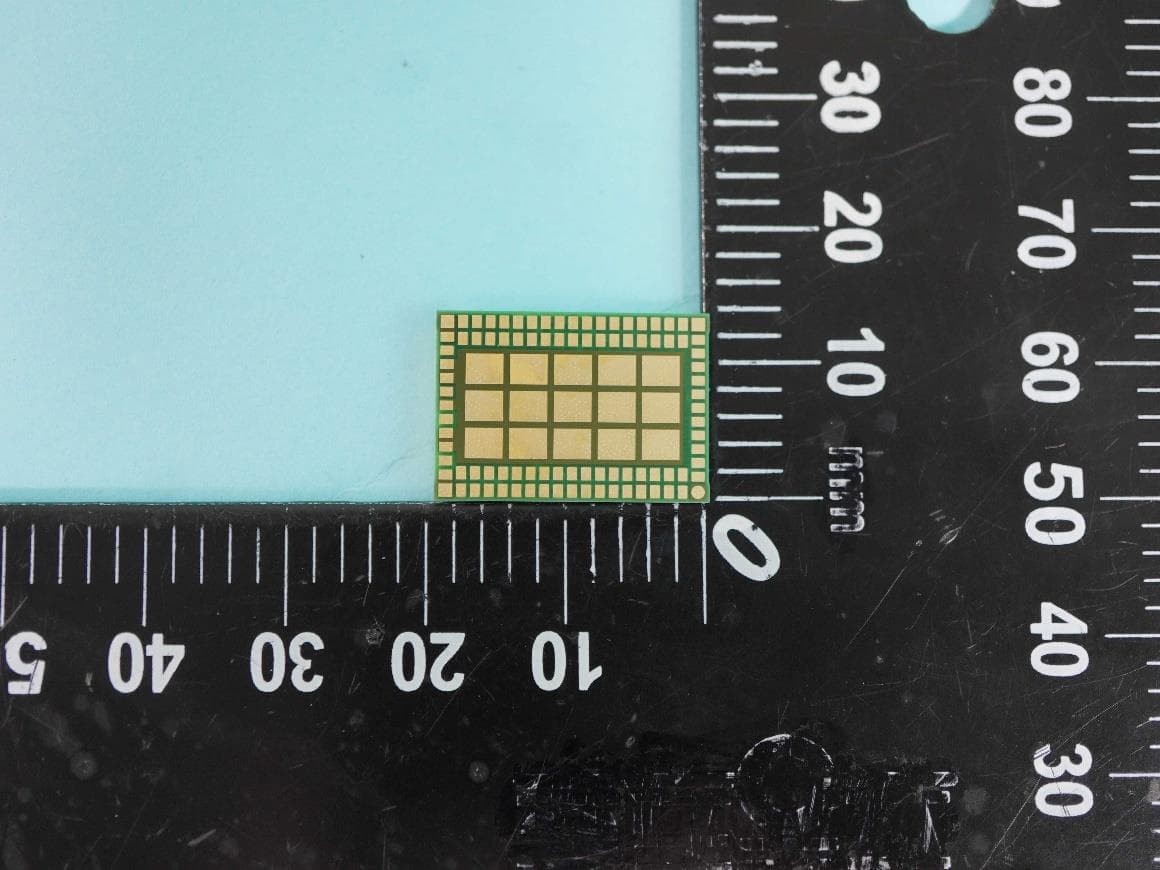
XPYJODYB1
Aug 07, 2026BT Module
Equipment Class
DSS - Part 15 Spread Spectrum Transmitter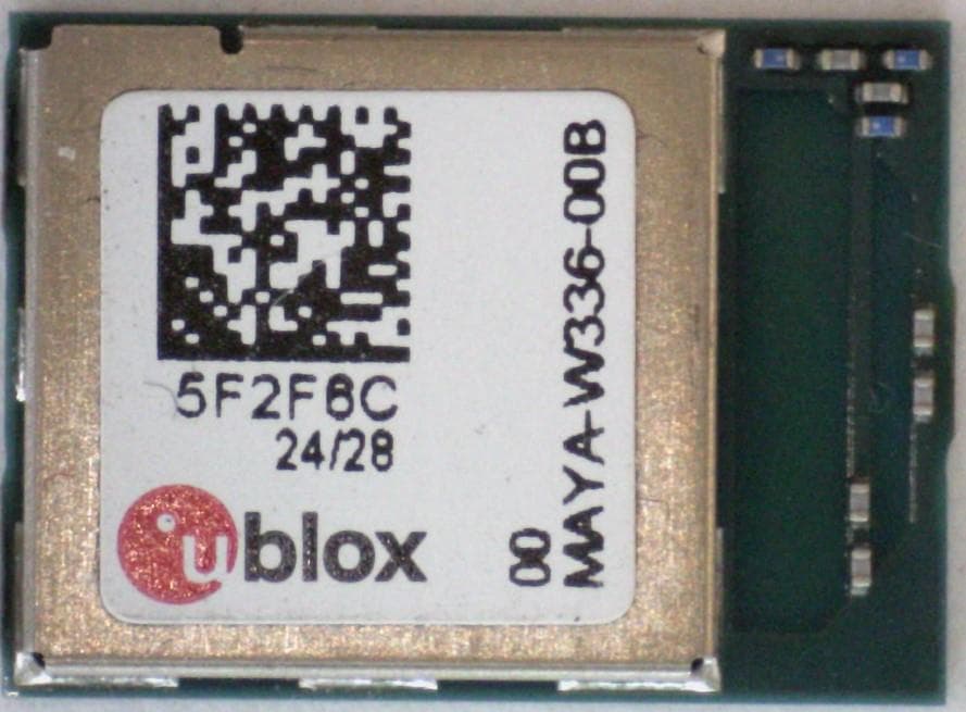
XPYMAYAW3A
Feb 01, 2026WLAN and Bluetooth module
Equipment Class
6XD - 15E 6 GHz Low Power Indoor Client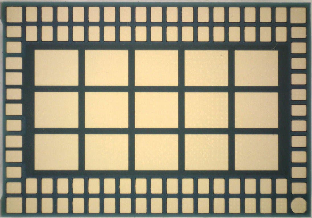
XPYJODYW6A
Jan 22, 2026WLAN and Bluetooth module
Equipment Class
NII - Unlicensed National Information Infrastructure TX
XPYIRISW1
Jul 21, 2024Stand-alone Tri-radio wireless MCU module
Equipment Class
DTS - Digital Transmission SystemXPYUBX23AD01
Jun 30, 2024Cat1 bis data only module
Equipment Class
PCB - PCS Licensed Transmitter