XPYUBX19KM01LTE CAT-M1 Data Module
u-blox AG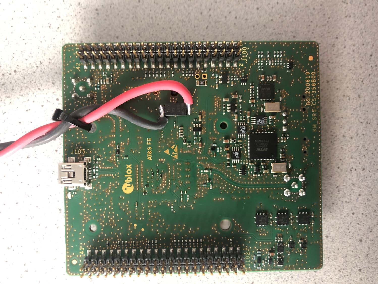
Click to zoom
Application Details
- Equipment Class
- PCB - PCS Licensed Transmitter
- Date of Grant
- Jul 22, 2020
- Application Purpose
- Original Equipment
- Date of Application
- Jul 22, 2020
- Equipment Note
- LTE CAT-M1 Data Module
- Frequency Range
- 814.70000000 - 823.30000000
- Company
- u-blox AG
- Country
- Switzerland
Documents & Files
Document Text
Text extracted from the exhibit documents filed with the FCC. Open a document above to read the original.
Users Manual
SARA-R5 series Multi-band LTE-M / NB-IoT modules System integration manual Abstract This document describes the features and the integration of the size-optimized SARA-R5 series cellular modules, based on the u-blox UBX-R5 cellular chipset. The modules are a size-optimized solution specifically designed for IoT, integrating an in-house developed cellular modem, end-to-end trusted domain security and u-blox’s leading GNSS technology. The modules deliver high performance satellite positioning alongside data connectivity in the very small and compact SARA form factor. www.u-blox.com UBX-19041356 - R03 SARA-R5 series - System integration manual UBX-19041356 - R03 Page 2 of 123 Confidential Document information Title SARA-R5 series Subtitle Multi-band LTE-M / NB-IoT modules Document type System integration manual Document number UBX-19041356 Revision and date R03 26-Mar-2020 Disclosure restriction Confidential Product status Corresponding content status Functional sample Draft For functional testing. Revised and supplementary data will be published later. In development / Prototype Objective specification Target values. Revised and supplementary data will be published later. Engineering sample Advance information Data based on early testing. Revised and supplementary data will be published later. Initial production Early production information Data from product verification. Revised and supplementary data may be published later. Mass production / End of life Production information Document contains the final product specification. This document applies to the following products: Product name Type number Modem version Application version PCN reference Product status SARA-R500S SARA-R500S-00B-00 N.A. N.A. N.A. Functional sample SARA-R510S SARA-R510S-00B-00 01.00 A00.01 UBX-20010454 Prototype SARA-R510M8S SARA-R510M8S-00B-00 01.00 A00.01 UBX-20010454 Prototype u-blox or third parties may hold intellectual property rights in the products, names, logos and designs included in this document. Copying, reproduction, modification or disclosure to third parties of this document or any part thereof is only permitted with the express written permission of u-blox. The information contained herein is provided “as is” and u-blox assumes no liability for its use. No warranty, either express or implied, is given, including but not limited to, with respect to the accuracy, correctness, reliability and fitness for a particular purpose of the information. This document may be revised by u-blox at any time without notice. For the most recent documents, visit www.u-blox.com. Copyright © u-blox AG. SARA-R5 series - System integration manual UBX-19041356 - R03 Page 3 of 123 Confidential Contents Document information ................................................................................................................................ 2 Contents .......................................................................................................................................................... 3 1 System description ............................................................................................................................... 6 1.1 Overview ........................................................................................................................................................ 6 1.2 Architecture ................................................................................................................................................. 8 1.3 Pin-out .......................................................................................................................................................... 11 1.4 Operating modes ....................................................................................................................................... 15 1.5 Supply interfaces ....................................................................................................................................... 17 1.5.1 Module supply input (VCC) .............................................................................................................. 17 1.5.2 Generic digital interfaces supply output (V_INT) ....................................................................... 20 1.6 System function interfaces .....................................................................................................................21 1.6.1 Module power-on ...............................................................................................................................21 1.6.2 Module power-off .............................................................................................................................. 24 1.6.3 Module reset ...................................................................................................................................... 26 1.7 Antenna interfaces ................................................................................................................................... 27 1.7.1 Cellular antenna RF interface (ANT) ............................................................................................. 27 1.7.2 GNSS antenna RF interface (ANT_GNSS) ................................................................................... 28 1.7.3 Cellular antenna detection interface (ANT_DET) ...................................................................... 29 1.7.4 Cellular and GNSS coexistence ...................................................................................................... 29 1.8 SIM interface .............................................................................................................................................. 31 1.8.1 SIM card interface ............................................................................................................................ 31 1.8.2 SIM card detection interface (GPIO5) ...............................................…
Text truncated - open the document above for the full version.
Attestation Statements
Author Jake Bascon Department: cert Page: 1/1 Filename SARA-R510M8S_Cover letter for CAT-M1 support only M102 Rev. 1 Copyright © 2013 u-blox SD, Inc. All rights reserved Confidential Certification Declaration Doc id: UBX-20010491 Rev.: 1.0 Date: 2/10/2020 Issued by: u-blox AG Zürcherstrasse 68 CH-8800 Thalwil / Switzerland Phone: +41 44 722 74 44 Fax: +41 44 722 74 47 [email protected] American Certification Body, Inc. 6731 Whittier Avenue Suite C110 McLean, VA 22101 To Whom It May Concern: FCC ID: XPYUBX19KM01 IC ID: 8595A-UBX19KM01 This device supports LTE CAT-M1 technology only. CAT-NB technology is currently not supported. We plan to add the CAT-NB technology support in future and will apply for both FCC and IC certification. Should there be any question, please feel free to contact us. Thank you, ___________________________________________________ Jake Bascon, Principal Certification Engineer
Cover Letter(s)
070920-02b Request for Modular/Limited Modular Approval Date: July 15, 2020 Subject: Manufacturer’s Declaration for ☒ - Modular Approval ☐ - Split Modular Approval ☐ - Limited Modular Approval ☐ - Limited Split Modular Approval Confidentiality Request for: XPYUBX19KM01 8 Basic Requirements – FCC Part 15.212(a)(1) For Items Marked “NO(*)”, the Limited Module Descri ption Must be Filled Out on the Following Pages Modular Approval RequirementRequirement Met 1. The modular transmitter must have its own RF shielding. This is intended to ensure that the module does not have to rely upon the shielding provided by the device into which it is installed in order for all modular transmitter emissions to comply with FCC limits. It is also intended to prevent coupling between the RF circuitry of the module and any wires or circuits in the device into which the module is installed. Such coupling may result in non-compliant operation. The physical crystal and tuning ca pacitors may be located external to the shielded radio elements. 15.212(a)(1)(i) ☒ - YES ☐ - NO(*) Details: <example – The module contains a metal shield which covers all RF components and circuitry. The shield is located on the top of the board next to antenna connector> 2. The modular transmitter must have buffered modulation/data inputs (if such inputs are provided) to ensure that the module will comply with FCC requirements under conditions of excessive data rates or over-modulation. 15.212(a)(1)(ii) ☒ - YES ☐ - NO(*) Details: <example – Data to the modulation circuit is buffered as described in the operational description provided with the application> 3. The modular transmitter must have its own power supply regulation on the module. This is intended to ensure that the module will comply with FCC requirements regardless of the design of the power supplying circuitry in the device into which the module is installed. 15.212(a)(1)(iii) ☒ - YES ☐ - NO(*) Details: <example – The module contains its own power supply regulation. Please refer to schematic filed with this application> 4. The modular transmitter must comply with the antenna and transmission system requirements of §§ 15.203, 15.204(b), 15.204(c), 15.212(a), and 2.929(b). The antenna must either be permanently attached or employ a ‘‘unique’’ antenna coupler (at all connections between the module and the antenna, including the cable). The ‘‘professional installation’’ provision of § 15.203 is not applicable to modules but can a pply to limited modular approvals under paragraph 15.212(b). 15.212(a)(1)(iv) ☒ - YES ☐ - NO(*) Details: <example – The module connects to its antenna using an UFL connector which is considered a non-standard connector. A list of antennas tested and approved with this device may be found in users manual provided with the application> 5. The modular transmitter must be tested in a stand-alone configuration, i.e., the module must not be inside another device during testing. This is intended to demonstrate that the module is capable of complying with Part 15 emission limits regardless of the device into which it is eventually installed. Unless the transmitter module will be battery powered, it must comply with the AC line conducted requirements found in Section 15.207. AC or DC power lines and data input/output lines connected to the module must not contain ferrites, unless they will be marketed with the module (see Section 15.27(a)). The length of these lines shall be length typical of actual use or, if that length is unknown, at least 10 centimeters to insure that there is no coupling between the case of the module and supporting equipment. Any accessories, peripherals, or support equipment connected to the module during testing shall be unmodified or commerciall y available (see Section 15.31(i)). 15.212(a)(1)(v) ☒ - YES ☐ - NO(*) Details: <example – The module was tested stand-alone as shown in test setup photographs filed with this application> 070920-02b Modular Approval Requirement Requirement Met 6. The modular transmitter must be labeled with its own FCC ID number, or use an electron display (see KDB Publication 784748). If using a permanently affixed label with its own FCC ID number, if the FCC ID is not visible when the module is installed inside another device, then the outside of the device into which the module is installed must also display a label referring to the enclosed module. This exterior label can use wording such as the following: “Contains Transmitter Module FCC ID: XYZMODEL1” or “Contains FCC ID: XYZMODEL1.” Any similar wording that expresses the same meaning may be used. The Grantee may either provide such a label, an example of which must be included in the application for equipment authorization, or, must provide adequate instructions along with the module which explain this requirement. In the latter case, a copy of these instructions must be included in the application for equipment authorization. If the modular transmitter uses an electronic display of the FCC identification number, the information must be readily accessible and visible on the modular transmitter or on the device in which it is installed. If the module is installed inside another device, then the outside of the device into which the module is installed must display a label referring to the enclosed module. This exterior label can use wording such as the following: “Contains FCC certified transmitter module(s).” Any similar wording that expresses the same meaning may be used. The user manual must include instructions on how to access the electronic display. A copy of these instructions must be included in the application for e quipment authorization. 15.212(a)(1)(vi) ☒ - YES ☐ - NO(*) Details: <example – There is a label on the module as shown in the labeling exhibit filed with this application. Host specific labeling instructions are shown in the installation manual .filed with this application.> 7. The modular transmitter must comply with all specific rule o…
Text truncated - open the document above for the full version.
Cover Letter(s)
Author Jake Bascon Department: cert Page: 1/2 Filenam e SARA-R510M8S_FCC Authority Letter to act as Agent M102 Rev. 1 Copyright © 2013 u-blox SD, Inc. All rights reserved Confidential Certification Declaration Doc id: UBX- 20007661 Rev.: 1.0 Date: 2/10/2020 FCC Authority to act as Agent Issued by: u-blox AG Zürcherstrasse 68 CH-8800 Thalwil / Switzerland Phone: +41 44 722 74 44 Fax: +41 44 722 74 47 [email protected] Subject: Agent letter for FCC ID: XPYUBX19KM01 & IC ID: 8595A-UBX19KM01 To Whom It May Concern: u-blox AG declares that American Certification Body, Inc. 6731 Whittier Avenue Suite C110 McLean, VA 22101 is authorized to act on our behalf to act as our agent in the preparation of this application for equipment certification. We certify that we are not subject to denial of federal benefits, that includes FCC benefits, pursuant to Section 5301 of the Anti-Drug Abuse Act of 1988, 21 U.S.C. 862. Further, no party, as defined in 47 CFR 1.2002 (b), to the application is subject to denial of federal benefits, that includes FCC benefits. Agency Agreement Expiration Date: Nov 14 2020 Thank you, ___________________________________________________ Jake Bascon, Principal Certification Engineer Author Jake Bascon Department: cert Page: 2/2 Filenam e SARA-R510M8S_FCC Authority Letter to act as Agent M102 Rev. 1 Copyright © 2013 u-blox SD, Inc. All rights reserved Confidential Certification Declaration Doc id: UBX- 20007661 Rev.: 1.0 Date: 2/10/2020 u-blox SD, Inc. 12626 High Bluff Drive, Suite 200. San Diego, CA 92130 - USA u-blox SD, Inc. is a wholly owned subsidiary of u-blox AG
Cover Letter(s)
Author Jake Bascon Department: cert Page: 1/1 Filenam e SARA-R510M8S_Power_of_Attorney M102 Rev. 1 Copyright © 2013 u-blox Italia S.p.A. All rights reserved Confidential Certification Declaration Doc id: UBX-20008422 Rev.: 1.0 Date: 2/10/2019 Power of Attorney Issued by: u-blox AG Zürcherstrasse 68 CH-8800 Thalwil / Switzerland Phone: +41 44 722 74 44 Fax: +41 44 722 74 47 [email protected] Subject: Power of Attorney to 7Layers Gmbh To whom it may concern, Please be notified that we, u-blox AG, have assigned 7Layers Gmbh as our agent to arrange the matters relating to international country approvals, including submitting and revising documents and test reports. Any and all acts carried out by 7Layers Gmbh on the matters relating to international country approvals shall have the same legal authority as acts on our own behalf. Meanwhile, u-blox AG will be fully responsible for mass products to be in compliance with regulations. This authorization is limited to below equipment: Product Description: LTE Cat-M1 data only module Brand name: u-blox Model#: SARA-R510M8S Marketing Name: SARA-R510M8S Sincerely, u-blox AG ___________________________________________________ Jake Bascon, Principal Certification Engineer u-blox SD, Inc. 12626 High Bluff Drive, Suite 200. San Diego, CA 92130 - USA u-blox SD, Inc. is a wholly owned subsidiary of u-blox AG
Cover Letter(s)
Author Jake Bascon Department: cert Page: 1/3 Filenam e SARA-R510M8SSARA-R510M8S_TCB Request for FCC Confidentiality M102 Rev. 1 Copyright © 2013 u-blox SD, Inc. All rights reserved Confidential Certification Declaration Doc id: UBX-20007664 Rev.: 1.0 Date: 2/10/2020 TCB Request for Confidentiality Issued by: u-blox AG Zürcherstrasse 68 CH-8800 Thalwil / Switzerland Phone: +41 44 722 74 44 Fax: +41 44 722 74 47 [email protected] Receiver: American Certification Body, Inc. 6731 Whittier Avenue Suite C110 McLean, VA 22101 Subject: Confidentiality Request for: FCC: XPYUBX19KM01 Model Name: SARA-R510M8S Pursuant to FCC 47 CRF 0.457(d) and 0.459 of the Commission Rules, the applicant requests that a part of the subject FCC application be held confidential. Type of Confidentiality Requested Exhibit Short Term Permanent Block Diagrams Short Term External Photos Short Term Internal Photos Short Term Permanent Operation Description/Theory of Operation Short Term Permanent Parts List & Placement/BOM Short Term Permanent Tune-Up Procedure Short Term Permanent Schematics Short Term Test Setup Photos Short Term User’s Manual u-blox AG, Zuercherstrasse 68, 8800 Thalwil, Switzerland has spent substantial effort in developing this product and it is one of the first of its kind in industry. Having the subject information easily available to "competition" would negate the advantage they have achieved by developing this product. Not protecting the details of the design will result in financial hardship. Permanent Confidentiality: Author Jake Bascon Department: cert Page: 2/3 Filenam e SARA-R510M8SSARA-R510M8S_TCB Request for FCC Confidentiality M102 Rev. 1 Copyright © 2013 u-blox SD, Inc. All rights reserved Confidential Certification Declaration Doc id: UBX-20007664 Rev.: 1.0 Date: 2/10/2020 The applicant requests the exhibits listed above as permanently confidential be permanently withheld from public review due to materials that contain trade secrets and proprietary information not customarily released to the public. Short-Term Confidentiality: The applicant requests the exhibits selected above as short term confidential be withheld from public view for a period of 180 days from the date of the Grant of Equipment Authorization and prior to marketing. This is to avoid premature release of sensitive information prior to marketing or release of the product to the public. Applicant is also aware that they are responsible to notify ACB in the event information regarding the product or the product is made available to the public. ACB will then release the documents listed above for public disclosure pursuant to FCC Public Notice DA 04-1705. NOTE for Industry Canada Applications: The applicant understands that until such time that IC distinguishes between Short Term and Permanent Confidentiality, either type of marked exhibit above will simply be marked Confidential when submitted to IC ___________________________________________________ Jake Bascon, Principal Certification Engineer Author Jake Bascon Department: cert Page: 3/3 Filenam e SARA-R510M8SSARA-R510M8S_TCB Request for FCC Confidentiality M102 Rev. 1 Copyright © 2013 u-blox SD, Inc. All rights reserved Confidential Certification Declaration Doc id: UBX-20007664 Rev.: 1.0 Date: 2/10/2020 u-blox SD, Inc. 12626 High Bluff Drive, Suite 200. San Diego, CA 92130 - USA u-blox SD, Inc. is a wholly owned subsidiary of u-blox AG
External Photos
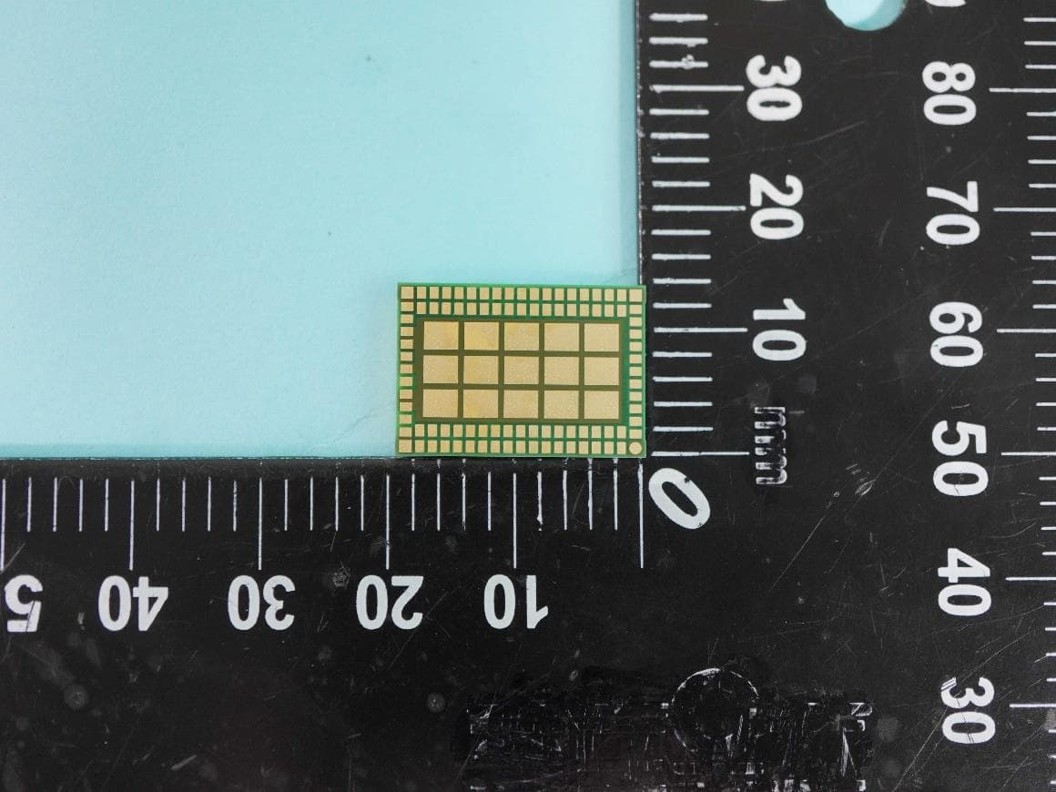
Back side of Module Back side of module test jig .
RF Exposure Info
Test Laboratory: 7layers GmbH Borsigstraße 11 40880 Ratingen Germany Note: The following test results relate only to the devices specified in this document. This report shall not be reproduced in parts without the written approval of the test laboratory. 7layers GmbH Registergericht registered in: Borsigstraße 11 Geschäftsführer / Düsseldorf, HRB 75554 40880 Ratingen, Germany Managing Directors: USt-IdNr VAT No.: T +49 (0) 2102 749 0 Frank Spiller DE203159652 F +49 (0) 2102 749 350 Bernhard Retka TAX No. 147/5869/0385 www.7layers.com Alexandre Norré-Oudard A Bureau Veritas Group Company RF Exposure and Maximum ERP/EIRP Assessment For SARA‐R510M8S CAT‐M1 Data Module embedding u‐blox Chipset Model UBX‐R5, HW: UBX‐R5231 FW: 00.14 FCC ID: XPYUBX19KM01 IC: 8595A‐UBX19KM01 Assessment Reference: MDE_UBLOX_1905_MPE_01_rev03 Assessment Reference: MDE_UBLOX_1905_MPE_01_rev03 Page 2 of 7 Table of Contents 0 Summary 3 0.1 Technical Report Summary 3 1 Administrative Data 4 1.1 Testing Laboratory 4 1.2 Project Data 4 1.3 Applicant Data 4 1.4 Manufacturer Data 4 2 Test object Data 5 2.1 General EUT Description 5 2.2 EUT Main components 5 2.3 Ancillary Equipment 5 2.4 Auxiliary Equipment 5 3 RF Exposure Evaluation for Module 6 Assessment Reference: MDE_UBLOX_1905_MPE_01_rev03 Page 3 of 7 0 Summary 0.1 Technical Report Summary Ty pe of Report RF Exposure Assessment for a LTE CAT‐M1 data module. Applicable FCC and ISED Rules For RF Exposure: OET Bulletin 65 Edition 97‐01 August 1997 FCC 47 CFR §1.1307 FCC 47 CFR §1.1310 RSS‐102 Issue 5 – March 2015 Fo r Maximum ERP/EIRP: FCC 47 CFR §22.913 IC RSS‐132, Issue 3 FCC 47 CFR §24.232 IC RSS‐133 Issue 6 FCC 47 CFR §27.50(d) RSS‐139, Issue 2 / SRSP‐513 FCC 47 CFR §90.635 RSS‐140, Issue 1 Report version control Rev Version Release date Changes Version validity ‐ 19.02.2020 Initial version invalid rev01 24.03.2020 Update for eFDD2, 13, 25 and 26 invalid rev02 25.03.2020 Update of table header chapter 3.2.3 invalid rev03 20.07.2020 Changed to only use Tune‐up values for MPE calculation valid Reviewer: Responsible for Report: Assessment Reference: MDE_UBLOX_1905_MPE_01_rev03 Page 4 of 7 1 Administrative Data 1.1 Testing Laboratory Company Name: 7layers GmbH Address Borsigstr. 11 40880 Ratingen Germany FCC accreditation Designation Number: DE0015 Test Firm Registration #: 929146 Industry Canada Test Site AcceptanceCAB identifier: DE0007 Test Firm Registration #: 3699A The test facility is also accredited by the following accreditation organisation: Laboratory accreditation no.: D‐PL‐12140‐01‐01, D‐PL‐12140‐01‐02, D‐PL‐12140‐01‐03 Responsible for Accreditation Scope:Dipl.‐Ing. Bernhard Retka Dipl.‐Ing. Robert Machulec Dipl.‐Ing. Andreas Petz Dipl.‐Ing. Marco Kullik Report Template Version: 2020‐02‐19 1.2 Project Data Responsible for assessment and report:Mr. Sören Berentzen Date of Report: 20.07.2020 1.3 Applicant Data Company Name: u‐blox AG Address: Zürcherstrasse 68, CH‐8800 Thalwil Switzerland Contact Person: Giulio Comar 1.4 Manufacturer Data Company Name: please see applicant data Address: Contact Person: Assessment Reference: MDE_UBLOX_1905_MPE_01_rev03 Page 5 of 7 2 Test object Data 2.1 General EUT Description Equipment under Test SARA‐R510M8S Type Designation: SARA‐R510M8S Kind of Device: CAT‐M1 Data Module embedding u‐blox Chipset Model UBX‐R5 HW: UBX‐R5231 FW: 00.14 GSM MSC/UMTS/LTE CAT CAT‐M1 FCC ID: XPYUBX19KM01 IC Number: 8595A‐UBX19KM01 General product description: The EUT is Cellular radio module supporting GSM/GPRS/WCDMA/HSDPA/HSUPA 2.2 EUT Main components Type, S/N, Short Descriptions etc. used in this Test Report Short Description Equipment under Test Type Designation Serial No. HW Status SW Status EUT A Code: DE1015116 ar11 SARA‐R510M8S R510M8S357862090047590352D0000.11 Remark: EUT A is equipped with a temporary antenna connector. The Module is not sold with a predefined antenna. NOTE: The short description is used to simplify the identification of the EUT in this test report. 2.3 Ancillary Equipment For the purposes of this test report, ancillary equipment is defined as equipment which is used in conjunction with the EUT to provide operational and control features to the EUT. It is necessary to configure the system in a typical fashion, as a customer would normally use it. But nevertheless, Ancillary Equipment can influence the test results. Short Description Equipment under Test Type Designation HW Status SW Status Serial no. FCC ID NA – 2.4 Auxiliary Equipment For the purposes of this test report, auxiliary equipment is defined as equipment which is used temporarily to enable operational and control features especially used for the tests of the EUT which is not used during normal operation or equipment that is used during the tests in combination with the EUT but is not subject of this test report. It is necessary to configure the system in a typical fashion, as a customer would normally use it. But nevertheless, Auxiliary Equipment can influence the test results. Short Description Equipment under Test Type Designation Serial no. HW Status SW Status FCC ID N/A – Assessment Reference: MDE_UBLOX_1905_MPE_01_rev03 Page 6 of 7 3 RF Exposure Evaluation for Module Standards OET Bulletin 65 Edition 97‐01 August 1997 RSS‐102 Issue 5 – March 2015 3.1.1 Test limits As specified in Table 1B of 47 CFR 1.1310 – Limits for Maximum Permissible Exposure (MPE), Limits for General Population/Uncontrolled Exposure. Frequency range (MHz)Power density (mW/cm²) 300 –1,500f/1500 1,500 –100,0001.0 Limits specified per RSS‐102, Issue 5. Frequency range (MHz) Power density (W/m²)Power density (mW/cm²) 300 – 6000 0.02619 f 0.6834 mW/cm² = W/m² * 0.1 Equation OET bulletin 65, page 18, edition 97‐01: 푆ൌ ீ ସగோ మ ൌ ாூோ ସగோ² Where: S = power density P = power input to the antenna G = power gain of the antenna in the direction of interest relative to an isotropic radiator R = distance to the centre of radiation of the antenna 3.1.2 Test Protocol Maximum antenna gain to comply …
Text truncated - open the document above for the full version.
Test Report
Test Laboratory: 7layers GmbH Borsigstrasse 11 40880 Ratingen Germany Note: The following test results relate only to the devices specified in this document. This report shall not be reproduced in parts without the written approval of the test laboratory. 7layers GmbHGeschäftsführer/ Borsigstraße 11 Managing Directors: Registergericht/registered: a Bureau Veritas 40880 Ratingen, Germany Frank Spiller Düsseldorf HRB 75554 Group Company T +49 (0) 2102 749 0 Bernhard Retka USt-Id.-Nr./VAT-No. DE203159652 F +49 (0) 2102 749 350 Alexandre Norré-Oudard Steuer-Nr./TAX-No. 147/5869/0385 www.7layers.com Commerzbank AG Account No. 303 016 000 Bank Code 300 400 00 IBAN DE81 3004 0000 0303 0160 00 Swift Code COBADEFF FCC Measurement/Technical Report on SARA-R510M8S FCC ID: XPYUBX19KM01 IC: 8595A-UBX19KM01 Test Report Reference: MDE_UBLOX_1905_FCC_01_rev01 TEST REPORT REFERENCE: MDE_UBLOX_1905_FCC_01_rev01 Page 2 of 151 Table of Contents 1 Applied Standards and Test Summary 4 1.1 Applied Standards 4 1.2 FCC-IC Correlation Table 7 1.3 Measurement Summary / Signatures 10 2 Revision History 22 3 Administrative Data 23 3.1 Testing Laboratory 23 3.2 Project Data 23 3.3 Applicant Data 23 3.4 Manufacturer Data 23 4 Test object Data 24 4.1 General EUT Description 24 4.2 EUT Main components 24 4.3 Ancillary Equipment 24 4.4 Auxiliary Equipment 24 4.5 EUT Setups 25 4.6 Operating Modes 25 4.7 Product labelling 26 5 Test Results 27 5.1 RF Output power 27 5.2 Frequency stability 30 5.3 Spurious emissions at antenna terminals 33 5.4 Field strength of spurious radiation 36 5.5 Emission and occupied bandwidth 42 5.6 Band edge compliance 46 5.7 Peak-average-ratio49 5.8 RF Output power 52 5.9 Frequency stability 55 5.10 Spurious emissions at antenna terminal 58 5.11 Field strength of spurious radiation 61 5.12 Emission and occupied bandwidth 67 5.13 Band edge compliance 71 5.14 Peak to Average Ratio 74 5.15 RF Output Power 77 5.16 Frequency stability 81 5.17 Spurious emissions at antenna terminals 86 5.18 Field strength of spurious radiation 93 5.19 Emission and occupied bandwidth 103 TEST REPORT REFERENCE: MDE_UBLOX_1905_FCC_01_rev01 Page 3 of 151 5.20 Band edge compliance 107 5.21 Peak to Average Ratio 113 5.22 RF Output Power 117 5.23 Frequency Stability 120 5.24 Spurious Emissions at antenna terminals 122 5.25 Field strength of spurious radiation 125 5.26 Emission and Occupied Bandwidth 132 5.27 Peak to Average Ratio 136 6 Test Equipment 139 7 Antenna Factors, Cable Loss and Sample Calculations 144 7.1 LISN R&S ESH3-Z5 (150 kHz – 30 MHz) 144 7.2 Antenna R&S HFH2-Z2 (9 kHz – 30 MHz) 145 7.3 Antenna R&S HL562 (30 MHz – 1 GHz) 146 7.4 Antenna R&S HF907 (1 GHz – 18 GHz) 147 7.5 Antenna EMCO 3160-09 (18 GHz – 26.5 GHz) 148 7.6 Antenna EMCO 3160-10 (26.5 GHz – 40 GHz) 149 8 Measurement Uncertainties 150 9 Photo Report 151 TEST REPORT REFERENCE: MDE_UBLOX_1905_FCC_01_rev01 Page 4 of 151 1 APPLIED STANDARDS AND TEST SUMMARY 1.1 APPLIED STANDARDS Ty pe of Authorization Certification for a cellular mobile device. Applicable FCC Rules Prepared in accordance with the requirements of FCC Rules and Regulations as listed in 47 CFR Ch.1 Parts 2 and 22, (10-1-18 Edition). The following subparts are applicable to the results in this test report. Part 2, Subpart J - Equipment Authorization Procedures, Certification Part 22, Subpart H – Cellular Radiotelephone Service § 22.905 – Channels for cellular se rvice § 22.913 – Effective radiated power limits § 22.917 – Emission limitations for cellular equipment The tests were selected and performed with reference to: FCC Public Notice 971168 applying “Measurement guidance for certification of licensed d igital transmitters” 971168 D01 v03r01, 2018-04-09 ANSI C63.26: 2015 Type of Authorization Certification for a cellular mobile device. Applicable FCC Rules Prepared in accordance with the requirements of FCC Rules and Regulations as listed in 47 CFR Ch.1 Parts 2 and 90, (10-1-18 Edition). The following subparts are applicable to the results in this test report. Part 2, Subpart J - Equipment Authorization Procedures, Certification Part 90; Private Land Mobile Radio Services Subpart S—REGULATIONS GOVERNING LICENSING AND USE OF FREQUENCIES IN THE 806- 824, 851-869, 896-901, AND 935-940 MHZ BANDS Subpart R—REGULATIONS GOVERNING THE LICENSING AND USE OF FREQUENCIES IN THE 763-775 AND 793-805 MHZ BAND S TEST REPORT REFERENCE: MDE_UBLOX_1905_FCC_01_rev01 Page 5 of 151 § 90.635 – Limitations on power and antenna height § 90.543 – Emission limitations § 90.539 – Frequency stabilit y The tes ts were selected and performed with reference to: FCC Public Notice 971168…
Text truncated - open the document above for the full version.
Contact Information
Applicant
Giulio Comar(Certification Manager)
Technical Contact
Test Firm
7layers GmbHBernhard Retka
Technical Specifications
| # | Rule Parts | Frequency Range | Power Output | Emission | Tolerance |
|---|---|---|---|---|---|
| 14 | 9 | 814.7 MHz - 823.3 MHz | 135.80 mW | 967KW7D | 0.1 ppm |
Other Applications from u-blox AG
XPYJODYB1
Aug 07, 2026BT Module
Equipment Class
DSS - Part 15 Spread Spectrum Transmitter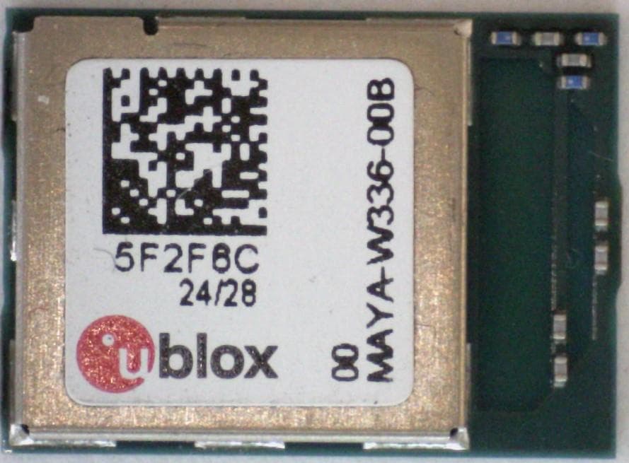
XPYMAYAW3A
Feb 01, 2026WLAN and Bluetooth module
Equipment Class
6XD - 15E 6 GHz Low Power Indoor Client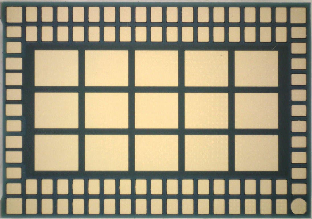
XPYJODYW6A
Jan 22, 2026WLAN and Bluetooth module
Equipment Class
NII - Unlicensed National Information Infrastructure TXXPYUBX22VA03
Jul 22, 2024NB CatM EGPRS data only module
Equipment Class
PCB - PCS Licensed Transmitter
XPYIRISW1
Jul 21, 2024Stand-alone Tri-radio wireless MCU module
Equipment Class
DTS - Digital Transmission System