XYEMOB1Maritime Survivor Locator Device
Ocean Signal Ltd.Application Details
- Equipment Class
- PLB - Personal Locator Beacons
- Date of Grant
- Mar 02, 2015
- Application Purpose
- Original Equipment
- Date of Application
- Jan 18, 2015
- Equipment Note
- Maritime Survivor Locator Device
- Frequency Range
- 161.97500000 - 162.02500000
- Company
- Ocean Signal Ltd.
- Country
- United Kingdom
Documents & Files
Document Text
Text extracted from the exhibit documents filed with the FCC. Open a document above to read the original.
Users Manual
User Manual MOB1 Maritime Survivor Locating Device English © 2014 Ocean Signal Ltd The technical data, information and illustrations contained in this manual were believed to be correct at the time of print. Ocean Signal Ltd reserve the right to change specifications and other information contained in this manual as part of our continual improvement process. No part of this manual may be reproduced, stored in a retrieval system or transmitted in any form, electronic or otherwise, without the prior permission of Ocean Signal Ltd. No liability can be accepted for any inaccuracies or omissions in this manual. Ocean Signal® and rescueME® are registered trademarks of Ocean Signal Ltd. MOB1 USER MANUAL 3 Version 00.03 08/10/2014 IN CASE OF EMERGENCY Use only in situations of grave or imminent danger NOTE: Refer to section 5.4 for deactivation instructions. MOB1 USER MANUAL 4 Part No 912S-01365 CONTENTS IN CASE OF EMERGENCY............................................................................................................................3 1. GENERAL ....................................................................................................................................5 1.1 Introduction................................................................................................................. 5 1.2 Exposure to RF Electromagnetic Energy .................................................................. 5 1.3 Warnings..................................................................................................................... 5 2. Lifejacket Installation .................................................................................................................5 3. MMSI configuration.....................................................................................................................7 3.1 Self Identification........................................................................................................ 7 3.2 User MMSI .................................................................................................................. 7 4. MOB1 OVERVIEW ........................................................................................................................9 5. OPERATION...............................................................................................................................10 5.1 Automatic Activation................................................................................................. 10 5.2 Manual Activation..................................................................................................... 10 5.3 DSC transmission..................................................................................................... 10 5.4 Deactivation .............................................................................................................. 11 6. TESTING ....................................................................................................................................11 6.1 Beacon test............................................................................................................... 12 6.2 DSC transmission test.............................................................................................. 12 6.3 AIS transmission test ............................................................................................... 12 7. APPENDIX .................................................................................................................................14 7.1 Maintenance and Troubleshooting .......................................................................... 14 7.2 Batteries ................................................................................................................... 14 7.3 Transport .................................................................................................................. 14 7.4 Disposal .................................................................................................................... 14 7.5 Specifications............................................................................................................ 15 7.6 Approvals.................................................................................................................. 16 7.7 Limited Warranty...................................................................................................... 18 MOB1 USER MANUAL 5 Version 00.03 08/10/2014 1. GENERAL 1.1 Introduction The rescueME range of products provides the user with the latest technology specifically designed for compact size and ease of operation. 1.2 Exposure to RF Electromagnetic Energy This product also complies with EN62479 (EU) and RSS-102 (Canada). This product has been evaluated for compliance with the FCC RF exposure limits given in CFR 47 part 1.307(b) at a distance of greater than 2cms. 1.3 Warnings An AIS-MOB Man OverBoard device is only intended for short range signalling to an AIS receiver installed onboard your own vessel. It will not directly alert the emergency services or other vessels. This equipment is not intended for routine tracking of persons or property. This includes routine tracking of divers. If self-test is performed more frequently than once a month, then battery life may be reduced. This radio device is designed to only provide an effective alerting and locating capability in close proximity to a vessel. This radio beacon is NOT an EPIRB. Cette radiobalise est conçue uniquement dans le but de fournir une fonction d’alerte et de localisation efficace à proximité immédiate d’un navire. Cette radiobalise n’est PAS une RLS. MOB1 USER MANUAL 6 Part No 912S-01365 2. Lifejacket Installation If your rescueME MOB1 is not already pre-installed lifejacket, please follow the instructions below carefully. • Loop the strap through the operating clip. • Clip the bracket to the MOB1 so that the MOB will be on the outside of …
Text truncated - open the document above for the full version.
Cover Letter(s)
FCC, Request for non-disclosure Date: 16-Jul-10 RF_501, Issue 6 Page 1 of 1 Company Name: Ocean Signal Ltd. Address: Unit 4, Ocivan Way City: Margate, CT9 4NN Country: United Kingdom To: Telefication B.V., Dept. FCC TCB Edisonstraat 12A 6902 PK ZEVENAAR The Netherlands Subject: Request for confidentiality FCC ID: XYEMOB1 Reference number: ###### Dear FCC TCB, 1. Long-Term Confidentiality Pursuant to 47 CFR Section 0.459(a) & (b), we hereby requests non-disclosure and confidential treatment of the following materials submitted in support of FCC certification application: Bill(s) of Material Block Diagrams Operational Description Schematic Diagrams Tune-up Procedure Above materials contain secrets, proprietary and technical information, which would customarily be guarded from competitors under 47 CFR, section 0.457(d)(2). Disclosure or publication or any portion of this company confidential material to other parties could cause substantial competitive harm and provide unjustified benefits for competitors. 2. Short-Term Confidentiality (STC) Pursuant to Public Notice DA 04-1705 of the Commission’s policy, in order to comply with the marketing regulations in 47 CFR §2.803 and the importation rules in 47 CFR §2.1204, a pplicant hereby requests Short-Term Confidential treatment of the following materials (note 1): Internal Photos User’s Manual Test Set-up Photos External Photos Justification: Planned Release Date STC: (notes 2, 3, 4, 5) Date: 18/12/2014 Name and signature of applicant: David Sheekey Notes: 1) A document or type of document can only have ONE type of confidentiality! 2) Short-Term confidentiality is in principle for 45 days from date of grant; it can be extended max 3 times (total time 180 days max.)! 3) FCC must be informed when marketing begins earlier. 4) Release takes place automatically thus extension must be requested in time. Telefication does not remind you of this! 5) Request for extension or for release must be received by Telefication at least 7 days before date of actual marketing or before expiration of the STC period
External Photos
Ocean Signal rescueME MOB1 – External Photographs Figure 1: rescueME MOB1 – Front View Figure 2: rescueME MOB1 – Left Hand Side View Figure 3: rescueME MOB1 - Right Hand Side View Figure 4: rescueME MOB1 – Rear View Approval information, including the FCC Identifier, will be printed on this label. Figure 5: rescueME MOB1 - Top View Figure 6 MOB1 showing antenna deployed and typical operational situation
ID Label/Location Info
FCC ID labels and location rescueME MOB1 Labels Figure 1: MOB1 Approvals Label showing FCC ID Figure 2: MOB1 FCC ID label location FCC Label fitted here
RF Exposure Info
Human Exposure to Electromagnetic Fields This document demonstrates that the Ocean Signal rescueME MOB1 Maritime Survivor Location Device is in compliance with US requirements for protection of the general public (uncontrolled) from exposure to electromagnetic fields. In the US regulation 47CFR chapter 1.1310 1 specifies that in the bands 30 – 300MHz the exposure limit is 0.2mW/cm 2 ; From Test Report TA0004 2 the measured EIRP at 156.525MHz is stated as 0.48mW. Duty Cycle= 0.5/300=0.0016 ∴Average power = 0.8mW Distance at which the power density meets the 0.2mW/cm 2 limit is given by: r = √(0.8/(4 x π x 0.2)) r = 0.6cms (=0.2inches) From Test Report TA0004 3 the measured EIRP at 161.975/162.025MHz is stated as 1580mW, with a duty cycle of (26ms*8)/(60000ms) = 0.00003. Distance at which the power density meets the 0.2mW/cm 2 limit is given by r = √(0.05/(4 x π x 0.2)) r = 0.14cms (= 0.1inches) According to the procedure in KDB447498 (v05r02) section 4.3, SAR testing is excluded if the following criteria is met. (P/d)* √f ≤3.0 for 1-g SAR Where P is the time averaged maximum conducted power in mW d minimum separation distance in mm f is the frequency in GHz 1 1.1310 Radiofrequency radiation exposure limits 2 Tested by Ocean Signal Ltd. 3 Tested by Ocean Signal Ltd Power and distance are rounded values. For d = 20mm, f = 162MHz and P = 0.85mW (0.8 +0.05) (0.85/20)* √0.162 = 0.017 Which is much less the value of 3 specified for exemption to 1-g SAR evaluation. Therefore the rescueME MOB1 meets the requirements for exposure to radiated electromagnetic fields at a worst case distance of 6.8cms from the transmitting antenna in both the USA and Europe. David Sheekey 18 th December 2014 Ocean Signal
Test Report
Test Report of the rescueME MOB1 to the requirements of RTCM SC11901 Annex A Test report No: TA0004-1 TA0004-1 Summary of Test Conditions Model: rescueME MOB1 Serial Number: PCB7 Dates Of Test: 05/12/14 to 10/12/14 Frequencies of Operation Channel 70 156.525MHz Extreme Conditions Upper Temperature = 55°C Lower Temperature = -20°C Rated Voltage = 6.0V Upper Voltage = 6.6V Lower Voltage = 3.8V Dates of Test : 05/12/14 to 10/12/14 Report Issued: 15/1/15 Tested By Stefan Kennedy Simon Nolan Approved by David Sheekey RTCM Standard SC11901.1 Maritime Survivor Locating Devices (MSLD) Annex A: DSC type MSLD 16/1/15Page 2 of 23 TA0004-1 Clause A4.1: Frequency Error Date of test: 05/12/14 to 10/12/14Temperature: 22.1Humidity: 36.7 Method Results 6.6V3.8V6.6V3.8V 156.525-40.0Hz40.0Hz40.0Hz-140.0Hz-140.0Hz140.0Hz Pass Limit Equipment used 1, 2, 4, 5, 6, The frequency error under normal conditions shall not exceed ±1.5 kHz, and under extreme test conditions shall not exceed ±1.5 kHz. -20°C55°C The carrier frequency shall be measured in the absence of of modulation, with the transmitter connected to an artificial and tuned to channel 70. Max ErrorPass / Fail Freq (MHz) Normal The measurement was made under normal test conditions and extreme test conditions. Transmitter under test Power Attenuator Frequency Meter 16/1/15Page 3 of 23 TA0004-1 Clause A4.4: Conducted Power Date of test: 05/12/14 to 10/12/14 Temperature: 22.1 Humidity: 36.7 Method Results 6.6V3.8V6.6V3.8V 156.52525.9dBm26.7dBm26.5dBm25.1dBm25.5dBm1.1dB Pass Limit Equipment used 1, 2, 4, 5, 6, The carrier power shall remain between 0.1 and 0.5Watts ±1.5dB of the rated power. The output power shall never however drop below 0.1Watts -20°C55°C The transmitter shall be connected to an artificial antenna (see clause 6.4) and the average or mean power delivered to this artificial antenna shall be measured under normal conditions (see clause 6.8), and at the extremes of temperature (see clause 6.9.1). The mean power under normal conditions P Norm shall be measured. The mean power under extreme conditions P -20 and P +55 shall be measured. The differences between the normal and extreme conditions shall be determined: P diff1 = P Norm - P -20 and P diff2 = P Norm - P +55 Error Pass / Fail Freq (MHz) Normal Transmitter under test RF Power Meter 16/1/15Page 4 of 23 TA0004-1 Clause A4.7:Adjacent Channel Power Date of test: 5/12/14 Temperature: 22.1 Humidity: 36.7 Method Results 6.6V3.8V6.6V3.8V 156.55070.1dBc70.1dBc Pass 156.50070.1dBc70.1dBc Pass Limit Equipment used ACP Pass / Fail Freq (MHz) Normal 4, 5, 6 The adjacent channel power can be measured with a power measuring receiver which conforms to annex B (referred to in clause 8.7.2 and annex B as the "receiver"), in Recommendation ITU-R SM.332-4: a) The transmitter shall be operated at the carrier power determined in clause 8.2 under normal test conditions. The output of the transmitter shall be linked to the input of the "receiver" by a connecting device such that the impedance presented to the transmitter is 50 Ω and the level at the "receiver" input is appropriate. b) With the transmitter unmodulated, the tuning of the "receiver" shall be adjusted so that a maximum response is obtained. This is the 0 dB response point. The "receiver" attenuator setting and the reading of the meter shall be recorded. The measurement may be made with the transmitter modulated with normal test modulation, in which case this fact shall be recorded with the test results. c) The tuning of the "receiver" shall be adjusted away from the carrier so that the "receiver" -6dB response nearest to the transmitter carrier frequency is located at a displacement from the nominal carrier frequency of 17 kHz for 25 kHz channels or 8,25 kHz for 12,5 kHz channels. d) The transmitter shall be modulated with the test signal specified in EN301 025-1 v1.5.2, using a continuous 01010101 data sequence. e) The "receiver" variable attenuator shall be adjusted to obtain the same meter reading as in step b) or a known relation to it. f) The ratio of adjacent channel power to carrier power is the difference between the attenuator settings in steps b) and e), corrected for any differences in the reading of the meter. g) The measurement shall be repeated with the "receiver" tuned to the other side of the carrier. The adjacent channel power shall not exceed a value of: • 25 kHz channel: 70 dB below the carrier power of the transmitter without any need to be below 0,2μW. -20°C55°C 16/1/15Page 5 of 23 TA0004-1 Date of test: 9/12/14 Temperature: 21.9Humidity: 35.2 Method Results Level (dBm) Pass/Fail -50Pass -43.4 Pass -42.4Pass -49.2Pass -44.7Pass -43.2Pass -44.04Pass -44.8Pass -40Pass -42.15Pass -48.65Pass -53.88Pass -59.47Pass -68.14Pass -67.07Pass -73.41Pass -73.62Pass -75.71 Pass No conducted spurious emissions exceeded -36dBm Refer to annex C plots 3 to 7 for results Limit The power of any conducted spurious emission shall not exceed 0.25uW (-36dBm) Equipment used 3, 5, 6, 22, 23 1095.67 1721.775 469.575 626.1 782.625 939.15 162.365 170.0066 182.00636 313.05 159.445 80.84 150.685 153.605 157.125 132.00738 RTCM 11901.1 Clause A.4.10: Conducted spurious emissions conveyed to the antenna Frequency (MHz) 19.2 77.00846 Conducted spurious emissions shall be measured with the unmodulated transmitter connected to the artificial antenna. The measurements shall be made over a range from 9 kHz to 2 GHz, excluding the channel on which the transmitter is operating and its adjacent channels. The measurements for each spurious emission shall be made using a tuned radio measuring instrument or a spectrum analyzer. 16/1/15Page 6 of 23 TA0004-1 Date of test: 16/12/14 Temperature: 6.6 Humidity: 44 Method Results LevelPass / Fail 0.081uWPass 0.004uWPass 0.008uWPass 0.018uWPass 0.029uWPass 0.632nWPass Refer to Annex D plots 8 and 9 for search scan results. Limit Equipment used Clause A4.13: Cabinet radiation and conducted spurious emissions other than those conve…
Text truncated - open the document above for the full version.
Test Report
Test Report of the rescueME MOB1 to the requirements of RTCM SC11901 Annex E Test report No: TA0004-2 Printed: 16/1/15 Printed: 16/1/15 TA0004-2 Summary of Test Conditions Frequencies of OperationUnless otherwise stated. AIS1 = 161.975MHz AIS2 = 162.025MHz Extreme Conditions Upper Temperature = 55°C Lower Temperature = -20°C Rated Voltage = 6.0V Upper Voltage = 6.6V Lower Voltage = 3.8V Dates of Test Tested By Stefan Kennedy Simon Nolan Approved by David Sheekey RTCM Standard SC11901.1 (June 2012) Maritime Survivor Locating Devices (MSLD) Annex A: DSC type MSLD Printed: 16/1/153 of 70 TA0004-2 Clause E.7.1.1.1: Frequency Error Date of test: 05/12/2014 to 10/12/14Temperature: 22.1°CHumidity: 36.7% Method The measurement was made under normal test conditions and extreme test conditions. Results 6.6V3.8V6.6V3.8V AIS1-20Hz40Hz41Hz-150Hz-150Hz-150HzPass AIS2-20Hz40Hz40Hz-150Hz-150Hz-150HzPass Limit Equipment used The frequency error of the transmitter is the difference between the measured carrier frequency in the absence of modulation and its required frequency. Error Pass / Fail ChannelNormal 1, 2, 3, 5, 6, 22 The frequency error under normal conditions shall not exceed ±500 Hz, and under extreme test conditions shall not exceed ±1 kHz. The equipment was connected as illustrated below. The carrier frequency shall be measured in the absence of modulation. -20°C55°C Transmitter under test Power Attenuator Frequency Meter Printed: 16/1/154 of 70 TA0004-2 Additional tests in accordance with CFR47 part 2.1055 Temp (Deg C) Supply (V) AIS 1AIS2DSC -206.6504040 -205.2504040 -203.8404040 -106.6606040 -105.2606040 -103.8606040 06.6606040 05.2606040 03.8606050 106.6656540 105.2656540 103.8656540 206.6555530 205.2555530 203.8555530 306.6-70-70-80 305.2-70-70-80 303.8-70-70-80 406.6-90-90-80 405.2-90-90-80 403.8-90-90-80 506.6-135-140-130 505.2-135-140-140 503.8-135-140-140 556.6-150-150-140 555.2-150-150-140 553.8-150-150-140 Frequency Error (Hz) Printed: 16/1/155 of 70 TA0004-2 Clause E.7.2: Conducted Power Date of test: 05/12/2014 to 10/12/14 Temperature: 22.1°C Humidity: 36.7% Method Results Conducted Power (dBm) 6.6V3.8V6.6V3.8V AIS132.0dBm32.2dBm32.3dBm31.8dBm31.6dBm AIS1+G32.2dBm32.3dBm31.8dBm31.6dBm31.6dBPass AIS232.0dBm32.1dBm32.3dBm31.8dBm31.6dBm AIS2+G32.1dBm32.3dBm31.8dBm31.6dBm31.6dBPass Limit Equipment used Calculate the gain of the AU antenna using the following equation: G = P r – P 20 – P d where G is the antenna gain (dB); P r is the radiated power level as measured in E.7.3 (dBm); P 20 is the conducted power level measured at normal test conditions (dBm); P d is the power output difference given in E.6.2 (dB). Hence G(dB) = 31.99 - 32 - 0 = 0.0dB Connect the test unit to a power meter and record the conducted power at normal test conditions (P 20 ). Repeat the test for extreme low and high temperatures and record the values obtained from these measurements (P −20 and P 55 ). P diff(max) Pass / Fail ChannelNormal 1, 2, 3, 5, 6, 22 The conducted power corrected for antenna gain shall be at least 27dBm -20°C55°C Transmitter under test RF Power Meter Printed: 16/1/156 of 70 TA0004-2 Clause E.7.3.3: Radiated Power Date of test: 1212/2014 Temperature: 8.5°C Humidity: 39.2% Method Results Pass / Fail 162.050MHz1.58W5.0dB Pass Limit Equipment used 3, 12 This test is only required to be performed at normal test conditions and shall use an AU whose battery has been ON for a minimum of 11 h. If the test exceeds 1h, the battery may be replaced by another which has been pre-conditioned with at least 11 h of ON time. Measurement of the radiated signals shall be made at a point 5 m or more from the AU. The ground plane should be resting on the ground. For an AU that floats autonomously the ground plane should be extended so that it completely encloses and presents a snug fit to the AU. For an AU that attaches to a life jacket or other buoyant device the AU shall be mounted on the buoyant device and deployed in a representative manner on the ground plane with its antenna base at a height of 10 ± 3cm. The measurement antenna shall have vertical polarization mounted on a non-conducting support with its cable lying horizontally on the boom and run back to the supporting mast. The other end of the measurement antenna cable shall be connected to a measurement receiver located at the foot of the mast The radiated power shall be at least 27dBm ChannelNormal The measurement shall be performed on a test site with a conductive ground plane of at least 3m diameter and the height of the measurement antenna shall be adjusted to obtain the maximum reading on the measurement receiver up to a maximum of 30° elevation. Record the measured receive level at 4 different points in the azimuth plane by rotating the AU in steps of 90°. The minimum received level (PREC) shall be recorded and used to calculate the radiated power at the normal operating temperature using the following equation: P r = P REC − G REC + L C + L P where P R is the radiated power level from the AU (dBm); P REC is the measured power level from the measurement receiver (dBm); G REC is the antenna gain of the search antenna (dB); L C is the receive system attenuator and cable loss (dB); L P is the free space propagation loss (dB) Printed: 16/1/157 of 70 TA0004-2 Clause 7.3.1.4: Modulation spectrum slotted transmission Date of test: 5/12/14Temperature: 22.1°CHumidity: 36.7% Method Results Pass - No emissions were above the limit line. Refer to annex B Plot 1 and Plot 2 for results. Limit Equipment used 3, 5, 6, 22 The transmitter shall be connected to an artificial antenna (see clause 6.4) with a means of measuring the power delivered to the load. The equipment shall be operated from the test power source (clause 6.7.2). Standard test signal number 3 (see clause 6.5.3) shall be used to modulate the transmitter in repeated packets. The measurement shall be made under normal test conditions. To determine the reference peak power and measure the emissions…
Text truncated - open the document above for the full version.
Test Setup Photos
Supplement to test report TA0004-1 & -2 Test Setup Photographs Figure 1: General view of Open Area Test Site Figure 2: View of Anechoic chamber from antenna end (Used for emission prescans and immunity) Figure 3: View of Anechoic chamber with microwave horn antenna. (Used for emissions above 1GHz)
Contact Information
Applicant
Mark Newton(Approvals Manager)
Technical Contact
Ocean Signal Ltd.David Sheekey
[email protected]4401843282930
Unit 4, Ocivan Way Margate, · United Kingdom
Non-Technical Contact
Ocean Signal Ltd.David Sheekey
[email protected]4401843282930
Technical Specifications
| # | Rule Parts | Frequency Range | Power Output | Emission | Tolerance |
|---|---|---|---|---|---|
| 2 | 95K | 161.975 MHz - 162.025 MHz | 1 W | 16K0GXW | 500 Hz |
Other Applications from Ocean Signal Ltd.
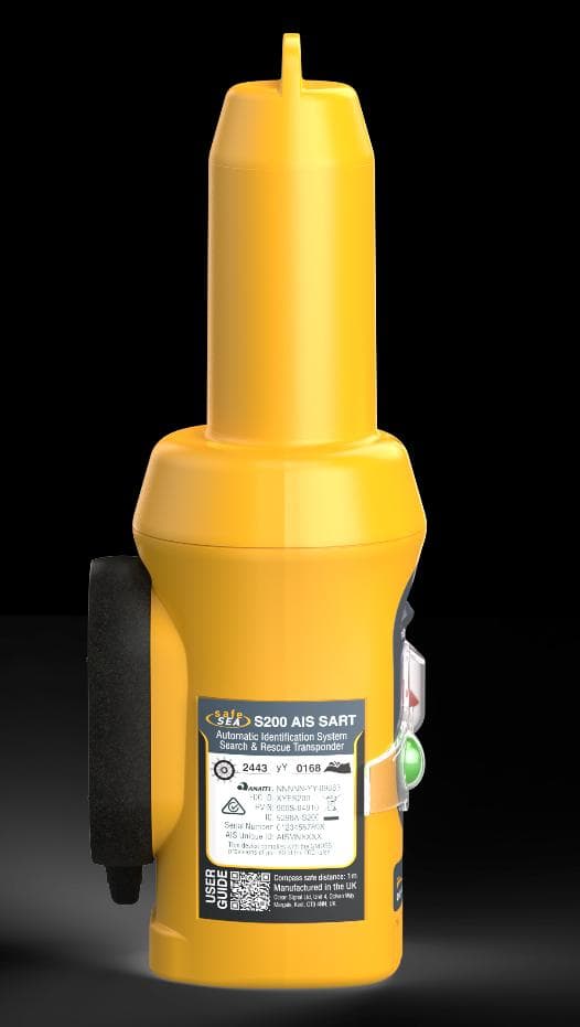
XYES200
Aug 20, 2026Search and Rescue Transmitter incorporating 162MHz AIS Man Overboard positioning capability
Equipment Class
AIS - Automatic Identification Systems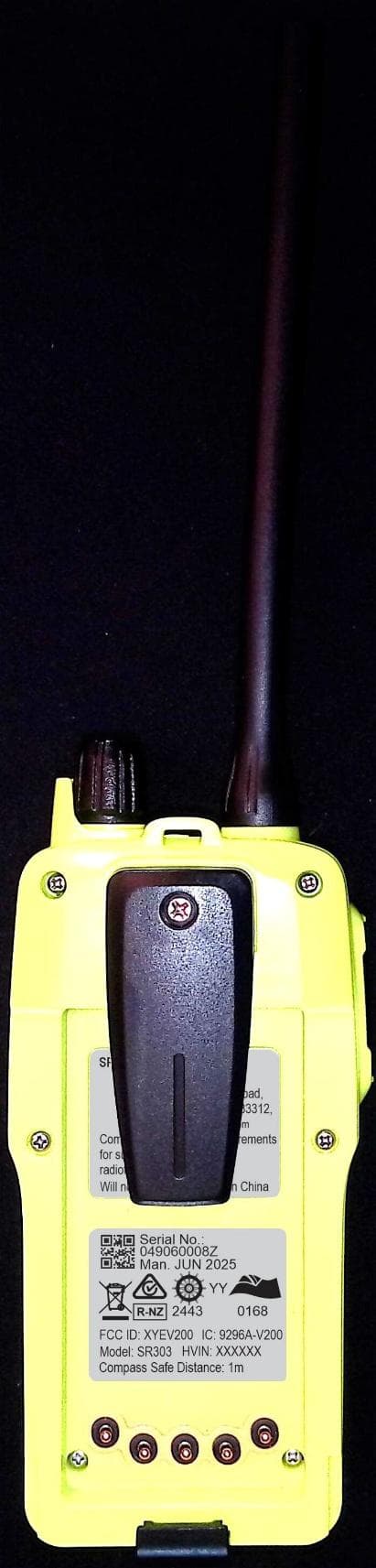
XYEV200
Feb 04, 2026GMDSS SURVIVAL CRAFT VHF RADIOTELEPHONE
Equipment Class
GHH - Part 80 VHF Hand Held Transmitter (GMDSS)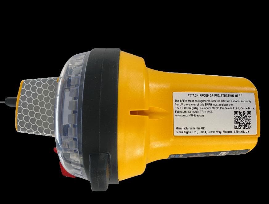
XYEEPIRB2
Jun 29, 2023406 MHz EPIRB with 121.5 MHz homing
Equipment Class
GEP - 406 MHz EPIRB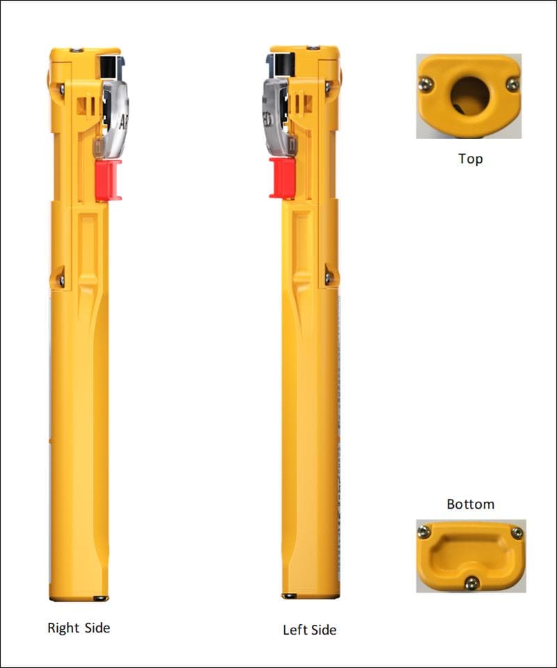
XYEPLB3
Jan 31, 2023PLB with AIS transceiver
Equipment Class
AIS - Automatic Identification Systems
XYEEPIRB3
Jan 25, 2023Marine AIS Transceiver with EPIRB
Equipment Class
GEP - 406 MHz EPIRB