XYEV200GMDSS SURVIVAL CRAFT VHF RADIOTELEPHONE
Ocean Signal Ltd.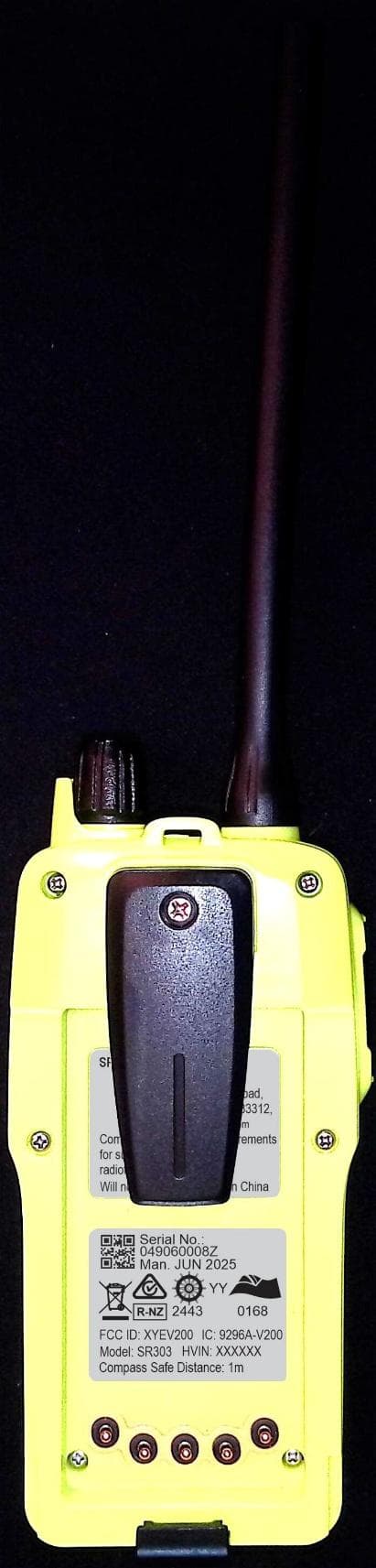
Click to zoom
Application Details
- Equipment Class
- GHH - Part 80 VHF Hand Held Transmitter (GMDSS)
- Date of Grant
- Feb 04, 2026
- Application Purpose
- Original Equipment
- Equipment Note
- GMDSS SURVIVAL CRAFT VHF RADIOTELEPHONE
- Frequency Range
- 156.02500000 - 157.42500000
- Company
- Ocean Signal Ltd.
- Country
- United Kingdom
Documents & Files
Document Text
Text extracted from the exhibit documents filed with the FCC. Open a document above to read the original.
Users Manual
Before operation pull out the red security tag from the battery. If the radio does not turn on automatically press the key (push the knob down). The radio will turn on with the distress and calling channel 16 already selected. Use the and keys to select a required channel. NOTE: Channels are restricted to GMDSS simplex only. Rotate the knob or use the VOL key followed by the and keys to adjust the speaker volume. Use the SQ key followed by the and keys to adjust the squelch (muting) level. Use the PUSH TO TALK key to transmit. To transmit a MAYDAY call the following procedure should be followed. Ensure the radio is turned on, channel 16 is selected and the PUSH TO TALK key is pressed. Announce the following clearly into the radio. MAYDAY - MAYDAY - MAYDAY This is [Ship’s Name] - This is [Ship’s Name] - This is [Ship’s Name] MAYDAY [Ship’s Name or Call Sign] Position..........[LAT and LON of description] Nature of Distress is...........[State the aid required] The number of persons on board is... [followed by any other information] Over OWNER DETAILS Name Vessel CONTACT Tel. Email 912S-05837 v01.00 19/06/2025 1. SR303 OVERVIEW Basic Parts 1. Antenna 2. ON/OFF and Multi Purpose Knob 3. Channel select Key 4. Multi Purpose Up/Down Key 5. Channel 16 select Key 6. Speaker and Microphone 7. Squelch select Key 8. Volume select Key 9. Push to Talk Key 10. LCD Display panel 1 2 3 4 5 6 7 8 10 9 Basic Display Indications 1. Primary Battery Indicator 2. Keypad Locked 3. Battery Life 4. Channel Number 5. Backlight On 6. Push to Talk Pressed 7. Squelch Value (0-9) 8. Volume Value (0-9) 9. 4 Digit Channel Number (with 4) 1 2 3 4 5 678 9 EMERGENCY USE ENSURE THE GREEN LITHIUM BATTERY PACK IS FITTED 1 2 3 4 5 6 7 SR303 GMDSS Handheld VHF Radio GET THE MOBILE APP. TO REGISTER YOUR HANDHELD VHF INFORMATION AndroidiOS NFC Communication Enabled https://www.acrartex.com/products/ sr303-vhf-handheld-survival-radio/ DOWNLOAD THE FULL USER GUIDE 3. NFC The SR 303 is capable of connection to devices using near field communication (NFC). NFC technology allows communication between two electronic devices over a distance of a few cm. The benefit of using NFC in the SR 303 is that the power used for communication comes from the mobile device and not the radio. The ACR mobile app allows a user to record the details of the radio and battery on your account with ACR. To use the app simply align your mobile device NFC antenna to the side of the V200 where you see “NFC”. Once connected, details about your V200 will be displayed on your mobile device including the product name and serial number. 4. Approvals 4.1 European Declaration of Conformity ACR Electronics Inc. declares equipment type SR 303 is in compliance with Dir. 2014/53/ EU. 4.2 Approval documentation For full details of global approval status visit: https://www.acrartex.com/products/sr303-vhf-handheld-survival-radio/ 5. Specifications Operating time (Primary battery) >8hours (10/10/80% Tx/Rx/Standby) Transmit power (conducted) (Primary battery) 2.5 Watts / ≤1 Watt Transmit power (conducted) (Rechargeable battery) 5 Watts / ≤1 Watt Audio ouput (Max. Volume) 86dBa @1m NFC Frequency 13.56MHz Dimensions of VHF (Inc. antenna) 279mm x 64mm x 37mm (11.0 x 2.5 x 1.5 in.) Weight (VHF Only) 422grams (0.92lbs) Dimensions of Single Base 52mm x 84mm x 64mm (2.0” x 3.3” x 2.5”) Dimensions of Charging Base 53mm x 84mm x 83mm (2.1” x 3.3” x 3.3”) Operating Temperature -20C to +55C Storage Temperature -30C to +70C Waterproof (VHF) 1m depth for 1 hour Expected Life (VHF) In excess of 10 years 1.1 GMDSS OPERATION Ensure the radio is fitted with a charged battery before commencing use. The primary battery will have the witness label intact indicating that it has full capacity (the label must be removed to operate). The display will indi- cate GMDSS when operating in this emergency mode. 1.2 First Level Operation Single quick press (single beep) of the buttons. 1.2.1 Switching On Press and hold the knob for >1 second to turn the SR 303 on. The LCD will illuminate and a beep will indicate power is on and the display will show the current information, with channel 16 as the selected channel. 1.2.2 Switching Off Press and hold the knob for 5 seconds to turn the radio off. The display will show a 3 second countdown, then the LCD will go blank. 1.2.3 Channel Selection Press the or keys to scroll through the available channels or press the TTWW DDWW WWX X CCHH button (the channel number will flash) and rotate the top knob. 1.2.4 Channel 16 selection Pressing the CCAALLLL SSCCAANN 1166 key will select channel 16. Pressing the CCAALLLL SSCCAANN 1166 key again will revert to the previous channel. 1.2.5 Transmitting Press the PUSH TO TALK key on the side of the radio to transmit. The microphone is located to the top left of the speaker grille. Release the key when you have finished talking. • It is good practice to keep transmissions as short as possible. This will minimise battery discharge and ensure that you are not interfering with other users of the channel. • Ensure the correct channel is selected and that there is no other transmission audible before pressing the PUSH TO TALK key to avoid interference with other users. 1.2.6 Volume Adjustment Rotate the knob to increase or decrease the speaker volume or press the HHii//LLoo VVOOLL key (the VOL level will flash) and then use the or keys to increase or decrease the speaker volume. The volume is displayed as levels 0 (mute) to 9 (loudest). 1.2.7 Squelch Adjustment Press the MMEENNUU EENNTT SSQQ key (the SQ level will flash) and then use the or keys or the knob to increase or decrease the squelch value. The squelch value is displayed as levels 0 (most sensitive) to 9 (least sensitive). ! The squelch should be adjusted to a level where background noise and weak, unreadable signals do not open the mute. 1.2.8 Backlight Adjustment To turn the lights on or off and adjust the level, press the knob and hold for 2 seconds (the light icon will f…
Text truncated - open the document above for the full version.
Users Manual
USER MANUAL GMDSS HANDHELD VHF RADIO 2 912S-05836 v01.01 20/01/2026 SR 303 VHF RADIO USER MANUAL Copyright © 2025 ACR Electronics, Inc. All contents of this manual are the intellectual property of ACR Electronics, Inc. This includes but is not limited to text, diagrams, illustrations and any other materials contained herein. No part of this manual may be altered and further produced in any form, electronic or mechanical, without the prior written permission of ACR Electronics, Inc. For permission requests or inquiries, please contact [email protected] ACR Electronics, Inc. reserves the right to change or update the contents of this manual without prior notice. While every effort has been made to ensure the accuracy of the information provided, ACR Electronics, Inc. assumes no responsibility for errors or omissions. Pathfinder TM is a registered trademark of ACR Electronics, Inc. For ease of access please record details of your SR 303 here: Owners Name: ....................................................... Vessel Name: ....................................................... Radio Serial Number: ....................................................... Primary Battery Expiry: ....................................................... 20/01/2023 912S-05836 v01.01 3 SR 303 VHF RADIO USER MANUAL • Before operation pull out the red security tag from the battery. • If the radio does not turn on automatically press the key (push the knob down). • The radio will turn on with the distress and calling channel 16 already selected. • Use the and keys to select a required channel. NOTE: Channels are restricted to GMDSS simplex only. • Rotate the knob or use the VOL key followed by the and keys to adjust the speaker volume. • Use the SQ key followed by the and keys to adjust the squelch (muting) level. • Use the PUSH TO TALK key to transmit. To transmit a MAYDAY call the following procedure should be followed. Ensure the radio is turned on, channel 16 is selected and the PUSH TO TALK key is pressed. Announce the following clearly into the radio. MAYDAY - MAYDAY - MAYDAY This is [Ship’s Name] - This is [Ship’s Name] - This is [Ship’s Name] MAYDAY [Ship’s Name or Call Sign] Position..........[LAT and LON of description] Nature of Distress is...........[State the aid required] The number of persons on board is...[followed by any other useful information] Over EMERGENCY USE ENSURE THE YELLOW LITHIUM BATTERY PACK IS FITTED 1 2 3 4 5 6 7 4 912S-05836 v01.01 20/01/2026 SR 303 VHF RADIO USER MANUAL 1. GENERAL 5 1.1 Introduction 5 1.2 Exposure to RF Electromagnetic Energy 5 1.3 Warnings 5 1.4 What’s in the Box 6 2. INSTALLATION 6 2.1 Mounting the cradle 6 2.2 Registering via the Mobile App 7 3.1 Basic Parts 8 3.2 Basic Display Indications 8 3. V200 OVERVIEW 8 4. GMDSS OPERATION 9 4.1 First Level Operation 9 4.2 Second Level Operation 10 4.3 Third Level Operation 11 5. RECHARGEABLE OPERATION 11 5.1 Primary Operation 11 5.2 Second Level Operation 13 5.3 Third Level Operation 13 6. MENU MODE 15 6.1 To enter MENU Mode 15 7. Appendix 17 7.1 Maintenance 17 7.2 Batteries 18 7.3 Decommissioning and Disposal 18 7.4 Transport 19 7.5 Channel Sets 20 7.6 General Specifications 26 7.7 Approvals 26 7.8 Spares 27 8. WARRANTY INFORMATION 27 8.1 Limited Warranty 27 20/01/2023 912S-05836 v01.01 5 SR 303 VHF RADIO USER MANUAL 1. GENERAL The SR 303 is supplied in the following packages: • GMDSS use only consisting of: SR 303 radio, antenna, lanyard (attached), Lithium emergency battery, mounting bracket, quick start guide. • GMDSS and daily use consisting of: SR 303 radio, antenna, lanyard (attached), Lithium emergency battery, Lithium Polymer rechargeable battery, charger, mains adaptor, supply lead, quick start guide. 1.1 Introduction This manual provides valuable information for the installation, operation and routine maintenance of the SR 303 radio and the charger, if included. Please read this manual completely before using your SR 303 radio. 1.2 Exposure to RF Electromagnetic Energy This product has been evaluated for compliance with the FCC RF exposure limits given in CFR 47 part 2.1093 at a distance of greater than 2.5cm. Highest Reported SAR1g[W/kg] in Body-Worn Exposure Condition, 0mm separation distance:0.76 W/kg 1.3 Warnings Do not operate this radio without the antenna attached or with a damaged antenna. Always operate the radio with the antenna at least 2.5cm (1inch) away from your head and do not transmit for more than 50% of the total time the radio is used. The use of this radio may be covered by licensing requirements in the country of use. Please check with your local regulatory body before use. Do not attempt to short circuit, burn, rupture the Lithium batteries. Use only the recommended charger for the rechargeable battery. 6 912S-05836 v01.01 20/01/2026 SR 303 VHF RADIO USER MANUAL 1.4 What’s in the Box 1. SR 303 VHF Handheld Radio 2. Primary (non-rechargeable) Battery 3. Rechargeable Battery * 4. Radio antenna 5. Wrist Lanyard 6. Cradle (GMDSS kit only) 7. Charging Cradle * 8. 110-240VAC Charger * 9. Quick Start Guide * Only included with the full use kit 2. INSTALLATION 2.1 Mounting the cradle In the ‘GMDSS pack’, the SR 303 is provided with a simple mounting cradle. In the full use kit’, the charger provided is used for storage of the radio. The cradle and charger can be wall mounted using the two self-tapping screws provided. Additionally the charger may be desktop mounted. Ensure the radio is mounted in accordance with IMO guidelines where applicable. The single cradle is supplied with the GMDSS kit to allow the radio to be secured in a suitable location to be accessible in case of emergency. The charging cradle allows the radio fitted with a rechargeable battery to charge while storing a Primary battery for use in an emergency situation. Both cradles can be attached to a vertical or horizontal surface using the supplied screws. 20/01/2023 912S-05836 v01.01 7 SR 303 VHF RADIO USER MANUAL 2.2 Registering …
Text truncated - open the document above for the full version.
Users Manual
Before operation pull out the red security tag from the battery. If the radio does not turn on automatically press the key (push the knob down). The radio will turn on with the distress and calling channel 16 already selected. Use the and keys to select a required channel. NOTE: Channels are restricted to GMDSS simplex only. Rotate the knob or use the VOL key followed by the and keys to adjust the speaker volume. Use the SQ key followed by the and keys to adjust the squelch (muting) level. Use the PUSH TO TALK key to transmit. To transmit a MAYDAY call the following procedure should be followed. Ensure the radio is turned on, channel 16 is selected and the PUSH TO TALK key is pressed. Announce the following clearly into the radio. MAYDAY - MAYDAY - MAYDAY This is [Ship’s Name] - This is [Ship’s Name] - This is [Ship’s Name] MAYDAY [Ship’s Name or Call Sign] Position..........[LAT and LON of description] Nature of Distress is...........[State the aid required] The number of persons on board is... [followed by any other information] Over OWNER DETAILS Name Vessel CONTACT Tel. Email 3. NFC The V200 is capable of connection to devices using near field communication (NFC). NFC technology allows communication between two electronic devices over a distance of a few cm. The benefit of using NFC in the V200 is that the power used for communication comes from the mobile device and not the radio. The Ocean Signal mobile app allows a user to record the details of the radio and battery on your account with Ocean signal. To use the app simply align your mobile device NFC antenna to the side of the V200 where you see “NFC”. Once connected, details about your V200 will be displayed on your mobile device including the product name and serial number. 4. Approvals 4.1 European Declaration of Conformity Ocean Signal Ltd. declares equipment type V200 is in compliance with Dir. 2014/53/EU. 4.2 Approval documentation For full details of global approval status visit: https://oceansignal.com/support/documents/?category%5B%5D=approvals-documents 5. Specifications Operating time (Primary battery) >8hours (10/10/80% Tx/Rx/Standby) Transmit power (conducted) (Primary battery) 2.5 Watts / ≤1 Watt Transmit power (conducted) (Rechargeable battery) 5 Watts / ≤1 Watt Audio output (Max. volume) 86dBa @1m NFC Frequency 13.56MHz Dimensions of VHF (Inc. antenna) 279mm x 64mm x 37mm (11.0 x 2.5 x 1.5 in.) Weight (VHF Only) 422grams (0.92lbs) Dimensions of Single Base 52mm x 84mm x 64mm (2.0” x 3.3” x 2.5”) Dimensions of Charging Base 53mm x 84mm x 83mm (2.1” x 3.3” x 3.3”) Operating Temperature -20C to +55C Storage Temperature -30C to +70C Waterproof (VHF) 1m depth for 1 hour Expected Life (VHF) In excess of 10 years V200 VHF DOWNLOAD THE FULL USER MANUAL https://oceansignal.com/ products/v200/ 912S-05835 v01.00 17/06/2025 GET THE MOBILE APP. TO REGISTER YOUR HANDHELD VHF INFORMATION Android iOS GMDSS Handheld VHF Radio 1. V200 OVERVIEW Basic Parts 1. Antenna 2. ON/OFF and Multi Purpose Knob 3. Channel select Key 4. Multi Purpose Up/Down Key 5. Channel 16 select Key 6. Speaker and Microphone 7. Squelch select Key 8. Volume select Key 9. Push to Talk Key 10. LCD Display panel 1 2 3 4 5 6 7 8 10 9 Basic Display Indications 1. Primary Battery Indicator 2. Keypad Locked 3. Battery Life 4. Channel Number 5. Backlight On 6. Push to Talk Pressed 7. Squelch Value (0-9) 8. Volume Value (0-9) 9. 4 Digit Channel Number (with 4) 1 2 3 4 5 678 9 EMERGENCY USE ENSURE THE YELLOW LITHIUM BATTERY PACK IS FITTED 1 2 3 4 5 6 7 Android iOS 1.1 GMDSS OPERATION Ensure the radio is fitted with a charged battery before commencing use. The primary battery will have the witness label intact indicating that it has full capacity (the label must be removed to operate). The display will indi- cate GMDSS when operating in this emergency mode. 1.2 First Level Operation Single quick press (single beep) of the buttons. 1.2.1 Switching On Press and hold the knob for >1 second to turn the SafeSea V200 on. The LCD will illuminate and a beep will indicate power is on and the display will show the current information, with channel 16 as the selected channel. 1.2.2 Switching Off Press and hold the knob for 5 seconds to turn the radio off. The display will show a 3 second countdown, then the LCD will go blank. 1.2.3 Channel Selection Press the or keys to scroll through the available channels or press the TTWW DDWW WWX X CCHH button (the channel number will flash) and rotate the top knob. 1.2.4 Channel 16 selection Pressing the CCAALLLL SSCCAANN 1166 key will select channel 16. Pressing the CCAALLLL SSCCAANN 1166 key again will revert to the previous channel. 1.2.5 Transmitting Press the PUSH TO TALK key on the side of the radio to transmit. The microphone is located to the top left of the speaker grille. Release the key when you have finished talking. • It is good practice to keep transmissions as short as possible. This will minimise battery discharge and ensure that you are not interfering with other users of the channel. • Ensure the correct channel is selected and that there is no other transmission audible before pressing the PUSH TO TALK key to avoid interference with other users. 1.2.6 Volume Adjustment Rotate the knob to increase or decrease the speaker volume or press the HHii//LLoo VVOOLL key (the VOL level will flash) and then use the or keys to increase or decrease the speaker volume. The volume is displayed as levels 0 (mute) to 9 (loudest). 1.2.7 Squelch Adjustment Press the MMEENNUU EENNTT SSQQ key (the SQ level will flash) and then use the or keys or the knob to increase or decrease the squelch value. The squelch value is displayed as levels 0 (most sensitive) to 9 (least sensitive). ! The squelch should be adjusted to a level where background noise and weak, unreadable signals do not open the mute. 1.2.8 Backlight Adjustment To turn the lights on or off and adjust the level, press the knob and hold for 2 seconds (the light icon will flash), rotate t…
Text truncated - open the document above for the full version.
Users Manual
User Manual www.oceansignal.com English GMDSS Handheld VHF Radio V200 V200 VHF Radio User Manual 2 912S-05834 Issue 01.01 20/01/2026 © 2025 Ocean Signal Ltd The technical data, information and illustrations contained in this manual were believed to be correct at the time of print. Ocean Signal Ltd reserves the right to change specifications and other information contained in this manual as part of our continual improvement process. No part of this manual may be reproduced, stored in a retrieval system or transmitted in any form, electronic or otherwise, without the prior permission of Ocean Signal Ltd. No liability can be accepted for any inaccuracies or omissions in this manual. Ocean Signal® and safeSEA® are registered trademarks of Ocean Signal Ltd. For ease of access please record details of your V200 here: Owners Name: ....................................................... Vessel Name: ....................................................... Radio Serial Number: ....................................................... Primary Battery Expiry: ....................................................... 20/01/2026 912S-05834 Issue 01.01 3 V200 VHF Radio User Manual • Before operation pull out the red security tag from the battery. • If the radio does not turn on automatically press the key (push the knob down). • The radio will turn on with the distress and calling channel 16 already selected. • Use the and keys to select a required channel. NOTE: Channels are restricted to GMDSS simplex only. • Rotate the knob or use the VOL key followed by the and keys to adjust the speaker volume. • Use the SQ key followed by the and keys to adjust the squelch (muting) level. • Use the PUSH TO TALK key to transmit. To transmit a MAYDAY call the following procedure should be followed. Ensure the radio is turned on, channel 16 is selected and the PUSH TO TALK key is pressed. Announce the following clearly into the radio. MAYDAY - MAYDAY - MAYDAY This is [Ship’s Name] - This is [Ship’s Name] - This is [Ship’s Name] MAYDAY [Ship’s Name or Call Sign] Position..........[LAT and LON of description] Nature of Distress is...........[State the aid required] The number of persons on board is... [followed by any other useful information] Over EMERGENCY USE ENSURE THE YELLOW LITHIUM BATTERY PACK IS FITTED 1 2 3 4 5 6 7 V200 VHF Radio User Manual 4 912S-05834 Issue 01.01 20/01/2026 1. GENERAL 5 1.1 Introduction 5 1.2 Exposure to RF Electromagnetic Energy 5 1.3 Warnings 5 1.4 What’s in the Box 6 2. INSTALLATION 6 2.1 Mounting the cradle 6 2.2 Registering via the mobile app 7 3.1 Basic Parts 8 3.2 Basic Display Indications 8 3. V200 OVERVIEW 8 4. GMDSS OPERATION 9 4.1 First Level Operation 9 4.2 Second Level Operation 10 4.3 Third Level Operation 11 5. RECHARGEABLE OPERATION 11 5.1 Primary Operation 11 5.2 Second Level Operation 13 5.3 Third Level Operation 13 6. MENU MODE 15 6.1 To enter MENU Mode 15 7. APPENDIX 17 7.1 Maintenance 17 7.2 Batteries 18 7.3 Decommissioning and Disposal 18 7.4 Transport 19 7.5 Channel Sets 20 7.6 General Specifications 26 7.7 Approvals 26 7.8 Spares 27 8. WARRANTY INFORMATION 27 8.1 Global Limited Warranty 27 20/01/2026 912S-05834 Issue 01.01 5 V200 VHF Radio User Manual 1. GENERAL The V200 is supplied in the following packages: • GMDSS use only, consisting of: V200 radio, antenna, lanyard (attached), Lithium emergency battery, mounting bracket, quick start guide. • GMDSS and daily use, consisting of: V200 radio, antenna, lanyard (attached), Lithium emergency battery, Lithium Polymer rechargeable battery, charger, mains adaptor, supply lead, quick start guide. 1.1 Introduction This manual provides valuable information for the installation, operation and routine maintenance of the V200 radio and the charger, if included. Please read this manual completely before using your V200 radio. 1.2 Exposure to RF Electromagnetic Energy This product has been evaluated for compliance with the FCC RF exposure limits given in CFR 47 part 2.1093 at a distance of greater than 2.5cm. Highest Reported SAR1g[W/kg] in Body-Worn Exposure Condition, 0mm separation distance:0.76 W/kg 1.3 Warnings Do not operate this radio without the antenna attached or with a damaged antenna. Always operate the radio with the antenna at least 2.5cm (1inch) away from your head and do not transmit for more than 50% of the total time the radio is used. The use of this radio may be covered by licensing requirements in the country of use. Please check with your local regulatory body before use. Do not attempt to short circuit, burn or rupture the Lithium batteries. Use only the recommended charger for the rechargeable battery. V200 VHF Radio User Manual 6 912S-05834 Issue 01.01 20/01/2026 1.4 What’s in the Box 1. V200 VHF Handheld Radio 2. Primary (non-rechargeable) Battery 3. Rechargeable Battery * 4. Radio antenna 5. Wrist Lanyard 6. Cradle (GMDSS kit only) 7. Charging Cradle * 8. 110-240VAC Charger * 9. Quick Start Guide * Only included with the full use kit 2. INSTALLATION 2.1 Mounting the cradle In the ‘GMDSS pack’, the safeSEA V200 is provided with a simple mounting cradle. In the full use kit’, the charger provided is used for storage of the radio. The cradle and charger can be wall mounted using the two self-tapping screws provided. Additionally the charger may be desktop mounted. Ensure the radio is mounted in accordance with IMO guidelines where appli- cable. The single cradle is supplied with the GMDSS kit to allow the radio to be secured in a suitable location to be accessible in case of emergency. The charging cradle allows the radio fitted with a rechargeable battery to charge while storing a Primary battery for use in an emergency situation. Both cradles can be attached to a vertical or horizontal surface using the supplied screws. 20/01/2026 912S-05834 Issue 01.01 7 V200 VHF Radio User Manual 2.2 Registering via the mobile app Download the mobile app and follow the instructions on screen. Use the mobile app to read th…
Text truncated - open the document above for the full version.
Internal Photos
Page 1 of 4 Document printed on 07/12/2025 Prepared by: S. Moore Ocean Signal Ltd Ocivan Way Margate CT9 4NN Date: 07/12/2025 COMMERCIAL-IN-CONFIDENCE Outdoor and Marine R&D 2025 SR 303 VHF Internal Photographs Technical Report Document No. NA Issue 01.00 Date Last Amended 07/12/2025 Last Amended by S. Moore Document Title SR 303 Internal Photographs Page 2 of 4 Document printed on 07/07/2025 Internal photographs of the SR 303 VHF are shown in Figures 1 to 4. Figure 1: SR 303 VHF Internal view showing PCB in-situ Technical Report Document No. NA Issue 01.00 Date Last Amended 07/12/2025 Last Amended by S. Moore Document Title SR 303 Internal Photographs Page 3 of 4 Document printed on 07/12/2025 Figure 2: SR 303 VHF Internal View with PCB removed Figure 3: SR 303 VHF PCB – Front Side Technical Report Document No. NA Issue 01.00 Date Last Amended 07/12/2025 Last Amended by S. Moore Document Title SR 303 Internal Photographs Page 4 of 4 Document printed on 07/12/2025 Figure 4: SR 303 VHF PCB – Rear Side with screening cans removed
Test Setup Photos
Technical Report OSL Part No. Other Part No. Approved: Issue 00.50 Date Last Amended 20/11/2025 Last Amended by S Moore Document Title V200 and SR 303 GMDSS VHF Handheld Radios Test Setup Photos Radiated Emissions Test Setup - 150 kHz to 30 MHz Test Setup - 30 MHz to 1 GHz Test Setup - 1 GHz to 2 GHz Immunity to Radiated Radio Frequencies Test Setup - Below 1 GHz Test Setup - Above 1 GHz Compass Safe Distance
Test Report
TÜV SÜD is a trading name of TUV SUD Ltd Registered in Scotland at East Kilbride, Glasgow G75 0QF, United Kingdom Registered number: SC215164 TUV SUD Ltd is a TÜV SÜD Group Company Phone: +44 (0) 1489 558100 Fax: +44 (0) 1489 558101 www.tuvsud.com/en TÜV SÜD Octagon House Concorde Way Fareham Hampshire PO15 5RL United Kingdom TÜV SÜD SIGNATURE NAME JOB TITLE RESPONSIBLE FOR ISSUE DATE Steve Marshall Senior Engineer Authorised Signatory 05 June 2025 Signatures in this approval box have checked this document in line with the requirements of TÜV SÜD document control rules. ENGINEERING STATEMENT The measurements shown in this report were made in accordance with the procedures described on test pages. All reported testing was carried out on a sample equipment to demonstrate limited compliance with FCC 47 CFR Part 80, FCC 47 CFR Part 2 and ISED RSS-182 and ISED RSS-GEN. The sample tested was found to comply with the requirements defined in the applied rules. RESPONSIBLE FOR NAME DATE SIGNATURE Testing Neil Rousell 05 June 2025 Testing Pier-Angelo Lorusso 05 June 2025 FCC Accreditation 492497/UK2010 Octagon House, Fareham Test Laboratory ISED Accreditation 12669A/UK0003 Octagon House, Fareham Test Laboratory EXECUTIVE SUMMARY A sample of this product was tested and found to be compliant with FCC 47 CFR Part 80: 2023, FCC 47 CFR Part 2: 2023, ISED RSS-182: Issue 6 (2021-06) and ISED RSS-GEN: Issue 5 (04-2018) + A2 (02-2021) for the tests detailed in section 1.3. FCC and ISED Test Report Manufacturer: Ocean Signal Limited GMDSS Radio (Green Radio), Model: V200 In accordance with FCC 47 CFR Part 80, FCC 47 CFR Part 2 and ISED RSS-182 and ISED RSS-GEN (GMDSS VHF) Prepared for: Ocean Signal Limited Ocivan Way Margate CT9 4NN United Kingdom FCC ID: XYEV200 IC: 9296A-V200 COMMERCIAL-IN-CONFIDENCE Document 75961609-04 Issue 01 DISCLAIMER AND COPYRIGHT This non-binding report has been prepared by TÜV SÜD with all reasonable skill and care. The document is confidential to the potential Client and TÜV SÜD. No part of this document may be reproduced without the prior written approval of TÜV SÜD. © 2025 TÜV SÜD. This report relates only to the actual item/items tested. ACCREDITATION Our UKAS Accreditation does not cover opinions and interpretations and any expressed are outside the scope of our UKAS Accreditation. Results of tests not covered by our UKAS Accreditation Schedule are marked NUA (Not UKAS Accredited). Results of tests covered by our Flexible UKAS Accreditation Schedule are marked FS (Flexible Scope). Document 75961609-04 Issue 01 COMMERCIAL-IN-CONFIDENCE COMMERCIAL-IN-CONFIDENCE Page 1 of 44 Contents 1 Report Summary .........................................................................................................................2 1.1 Report Modification Record ...........................................................................................................2 1.2 Introduction ....................................................................................................................................2 1.3 Brief Summary of Results .............................................................................................................3 1.4 Application Form ...........................................................................................................................4 1.5 Product Information .......................................................................................................................7 1.6 Deviations from the Standard ........................................................................................................7 1.7 EUT Modification Record ..............................................................................................................7 1.8 Test Location .................................................................................................................................7 2 Test Details ..................................................................................................................................8 2.1 Bandwidths ....................................................................................................................................8 2.2 Transmitter Frequency Tolerances ............................................................................................ 12 2.3 Spurious Emissions at Antenna Terminals ................................................................................ 15 2.4 Radiated Spurious Emissions .........................…
Text truncated - open the document above for the full version.
Contact Information
Applicant
Stefan Kennedy(Director of R&D)
[email protected]Fax: +441843293659
Technical Contact
ACR Electronics, Inc.Adam Sadowski
5757 Ravenswood Rd · Fort Lauderdale, Florida, 33312 · United States
Test Firm
TUV SUD LimitedNathan Emery
[email protected]Fax: 44 1489 558101
Technical Specifications
| # | Rule Parts | Frequency Range | Power Output | Emission | Tolerance |
|---|---|---|---|---|---|
| 1 | 80.1101(c)(7) | 156.025 MHz - 157.425 MHz | 2.9 W | 16K0G3E | 5.0000000000ppm |
Other Applications from Ocean Signal Ltd.
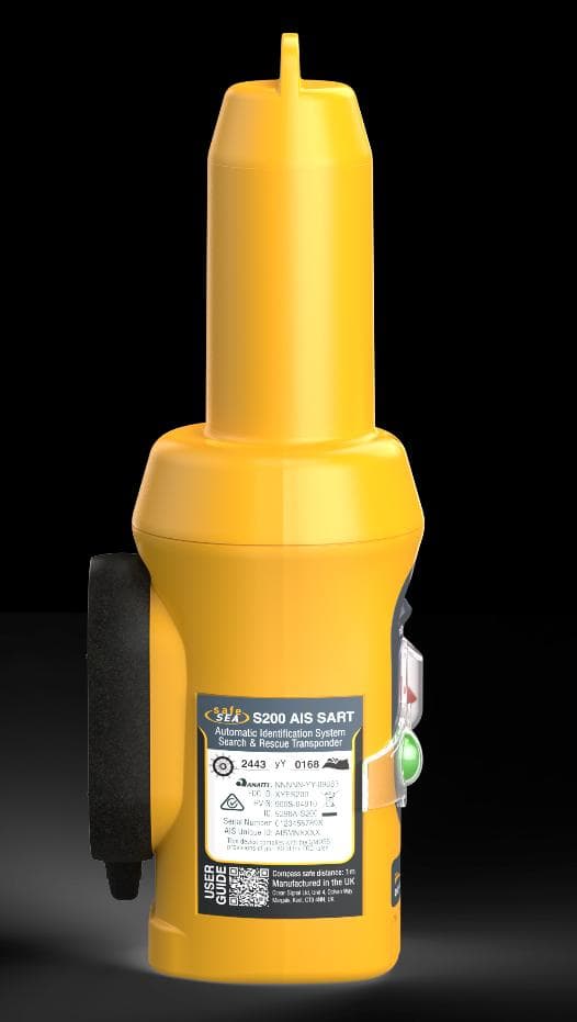
XYES200
Aug 20, 2026Search and Rescue Transmitter incorporating 162MHz AIS Man Overboard positioning capability
Equipment Class
AIS - Automatic Identification Systems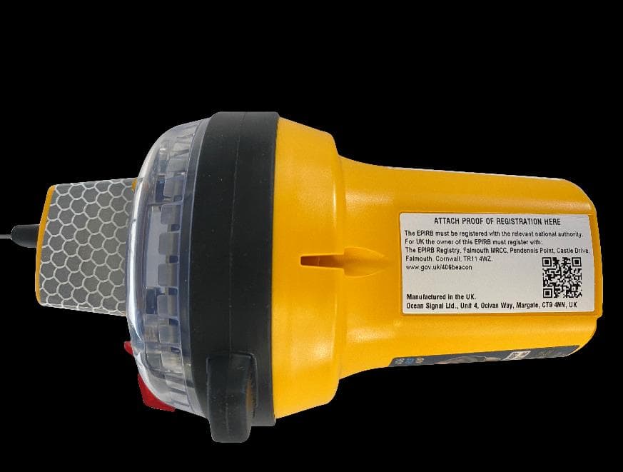
XYEEPIRB2
Jun 29, 2023406 MHz EPIRB with 121.5 MHz homing
Equipment Class
GEP - 406 MHz EPIRB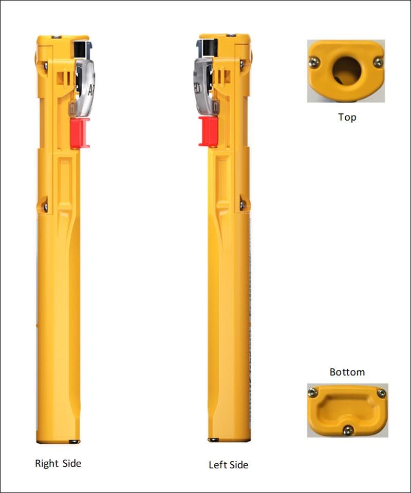
XYEPLB3
Jan 31, 2023PLB with AIS transceiver
Equipment Class
AIS - Automatic Identification Systems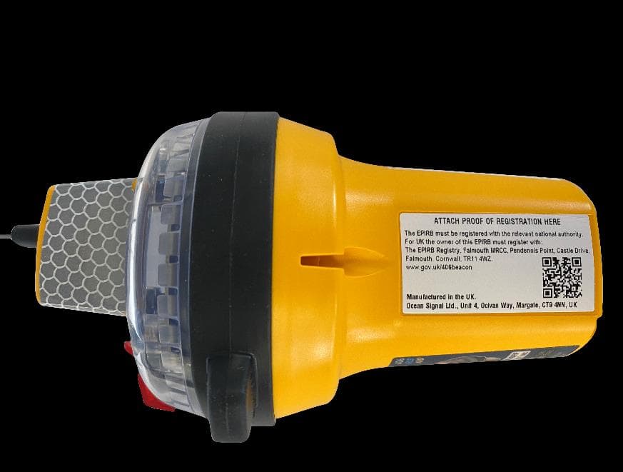
XYEEPIRB3
Jan 25, 2023Marine AIS Transceiver with EPIRB
Equipment Class
GEP - 406 MHz EPIRBXYEMOB1
Mar 02, 2015Maritime Survivor Locator Device
Equipment Class
PLB - Personal Locator Beacons