Y29-SA-ODLWireless hands-free access control
SecureALL Corporation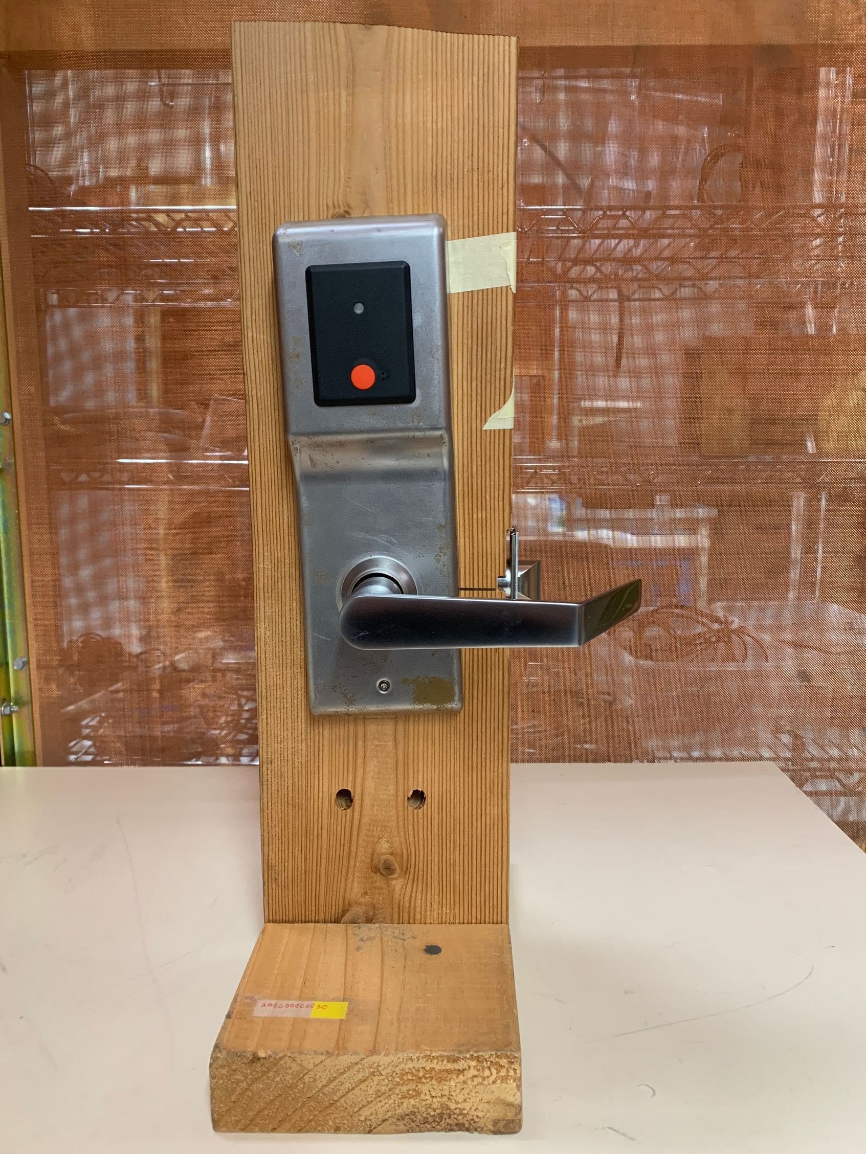
Click to zoom
Application Details
- Equipment Class
- DTS - Digital Transmission System
- Date of Grant
- May 13, 2020
- Application Purpose
- Original Equipment
- Date of Application
- May 13, 2020
- Equipment Note
- Wireless hands-free access control
- Frequency Range
- 2402.00000000 - 2480.00000000
- Company
- SecureALL Corporation
- Country
- United States
Documents & Files
Document Text
Text extracted from the exhibit documents filed with the FCC. Open a document above to read the original.
Users Manual
ODL User Guide v1.2 10 May 2020 sa-odl user guide v1.2.docx SecureALL Corporation, Proprietary Page: 1/5 SA-ODL User Guide (Electronic Door Reader Lock) Document History Version Date Author Changes, Remarks 1.0 05/04/2020 JS Initial document 1.1 5/5/2020 AS Review & augmented 1.2 5/10/2020 AS Edited per feedback from CT LLC. ODL User Guide v1.2 10 May 2020 sa-odl user guide v1.2.docx SecureALL Corporation, Proprietary Page: 2/5 1. Purpose 1.1. This document provides instructions on how to operate the SecureALL SA-ODL electronic door reader / lock product. 1.2. This document provides information about: 1.2.1. Product Operation – Magnetic Card Access 1.2.2. Product Operation – Keypad Access 1.2.3. Directions on how to interpret LED Blink sequence on lock Note: This is a living document that will change over the product lifecycle 2. Introduction & Product Overview 2.1. SA-ODL is a retrofit kit that converts a standard Onity’s CT30 lock (a standalone programming electronic door lock) into an on-line wireless lock. It provides real-time connectivity with the SA-Guardian application server, allowing system operators to remotely monitor, control and configures user’s ability to use a credential to unlock the electronic door lock. 2.2. The retrofit involves the following: 2.2.1. Use all parts of Onity-CT30 door lock except its original controller PCB assembly. 2.2.2. Replace Onity’s controller board with SecureALL’s wireless controller board 2.2.3. Add an outside antenna plate assembly (in most cases it is sandwiched between CT30 outside escutcheon & the door) 2.2.4. Adds an inside scutcheon cover 2.2.5. Adds an inside adapter PCB assembly with switch sensors, LEDs, connectors and an antenna. 2.2.6. A cable assembly 2.3. The product dynamically discovers nearby SA-AP-200 router and after establishing credentials, the SA-AP-200 router provides SA-ODL with data communication connectivity with SecureALL’s SA-Guardian Application Server. Figure 1: SA-ODL upgraded CT30 Outside escutcheon and Inside escutcheon ODL User Guide v1.2 10 May 2020 sa-odl user guide v1.2.docx SecureALL Corporation, Proprietary Page: 3/5 3. Caution & care 3.1. The SA-ODL is very simple to install and uses the same hole drill-out as a standard Onity-CT30 lock. 3.2. This device complies with part 15 of the FCC Rules. Operation is subject to the following two conditions: (1) This device may not cause harmful interference, and (2) this device must accept any interference received, including interference that may cause undesired operation. 3.3. To reduce potential radio interference to other users, the antenna type and its gain should be so chosen that the equivalent isotropically radiated power (E.I.R.P) is not more than that permitted for successful communication. 3.4. This device has been designed to operate with the antennas listed below, and having a maximum gain of 4dBi. Antennas not included in this list or having a gain greater than 4 dB are strictly prohibited for use with this device. The required antenna impedance is 50 ohms. Different Antenna mounting plate may be used to position the antenna in desired proximity to the lock cover (escutcheon). a. ODL Outside Antenna P/N: 810-000171 4. Modes of operation 4.1. Four operating modes are available to the SA-ODL upgraded lock: 4.1.1. Standard Mode – When the lock is in standard mode, a valid credential (card key) is required to gain access to the lock. 4.1.2. Office (Free) Mode – The locks may be configured to allow Office (or Free) access. When in this mode, no key is needed to gain access as the lock remains in the unlocked position. The locks may be placed in and out of office mode in two ways: a. Present certain authorized cards twice b. Automatically as per programmed schedule Note: Only credential cards that are valid for the lock may be used to put the lock in and out of office mode. 4.2. Lockdown or Blocked Mode – When a blocking card is presented to the lock, the Red LED will start flashing and the lock will enter blocking mode. When a lock is blocked, no guest keys, and only certain master users, will be allow access to the lock. To exit the blocking mode, present the blocking card again to the lock. The Green LED will flash once to indicate that the blocking has been removed. 4.3. Privacy Mode – When the privacy switch is engaged, typically when the deadbolt is engaged, only valid keys with the privacy override will be able to access the room. 5. SA-ODL Product Operation 5.1. The SA-ODL can be configured (as desired) for either: 5.1.1. Single-factor authentication (SFA): User may use either 5.1.1.1. Present a credential card 5.1.1.2. Press a secret PIN (personal identification number) code number on the Lock’s keypad. 5.1.2. Two-factor authentication (2FA): User shall first present a credential card followed by a pressing a secret PIN code number on the lock’s keypad. 5.2. Upon successful SFA or 2FA authentication ODL User Guide v1.2 10 May 2020 sa-odl user guide v1.2.docx SecureALL Corporation, Proprietary Page: 4/5 5.2.1. The LED turns green and 5.2.2. the lock is unlocked (for 4 seconds). Else 5.2.3. the LED turns red 6. Presenting a Credential card: Magnetic Card Access 6.1. Using a programmed magnetic-stripe card. 6.2. The user inserts the card into the lock’d card slot 7. Entering secret PIN number on the Keypad 7.1. The user presses on the lock’s keypad the secret PIN number. 8. SA-ODL LED indication codes 8.1. The SA-ODL has two LEDs which can be used in various combinations to provide the user feedback on their access attempts. 8.2. The meaning of various LED indications are as follows: 8.2.1. Solid green – Valid authentication. Door either unlocks or can proceed to next authentication step. 8.2.2. Solid red – Invalid card (or pin code). The user credential or PIN is not authorized access to the door lock. 8.2.3. Delayed solid red – Unreadable card. The lock recognizes that a card was inserted but is unable to interpret the information on the card. The c…
Text truncated - open the document above for the full version.
Cover Letter(s)
SECUREALL SECURITY REINVENTED SM May 4, 2020 Fe deral Communications Commission Authorization & Evaluation Division 7345 Oakland Mills Road Columbia, Maryland 21046 RE: Long-Term Confidentiality Request for SA-ODL; FCCID: Y29-SA-ODL To Whom It May Concern: This letter serves as an official request for confidentiality under§ 0.457(d) and § 0.459 of CFR 47. We have requested that the following documents required to be submitted with this application be permanently withheld from public review. •Block Di agram •Schematics •Theory of Operation •Parts List/BOM These documents contain detailed system and equipment descriptions and related information about the product, which manufacturer/applicant considers to be proprietary, confidential, and a custom design and otherwise, would not release to the general public. Since this design is a basis from which future technological products will evolve, manufacturer/applicant feels that this information would be of benefit to its competitors, and that the disclosure of the information in these documents would give our competitors an unfair advantage in the market. Please contact me if there is any information you may need. Sincerely yours, � Dr. Richard Schaffzin, CEO SecureALL Corporation • www.secureallcorp.com • [email protected] • 866.438.8539
ID Label/Location Info
FCC Label & location FCC ID: Y29-SA-ODL SecureALL Corporation Model No: SA-ODL Position of FCC label affixed on lock’s Inside cover 45.0mm. 12.5mm. FCC Label for Model: SA-ODL Position of the FCC Label File: FCC Label & location V1.vsd Sheet: Page-1 Date: 5/7/2020
Test Report
p2030012_FCC_Part 15.247_Rev 2.0 Page 1 of 19 Test Report Prepared for: SecureALL Coporation Model: SA-ODL Description: Electronic door reader/lock Serial Number: 00002 FCC ID: Y29-SA-ODL To FCC Part 15.247 IC RSS-247 Issue 2 Date of Issue: May 1, 2020 On the behalf of the applicant: SecureALL Coporation 900 Lafayette St Suite 202 Santa Clara, CA 95050 Attention of: Arun Sharma, Ph: (408)246-6227 E-Mail: [email protected] Pre pared By Compliance Testing, LLC 1724 S. Nevada Way Mesa, AZ 85204 (480) 926-3100 phone / (480) 926-3598 fax www.compliancetesting.com Project No: p2030012 Poona Saber Project Test Engineer This report may not be reproduced, except in full, without written permission from Compliance Testing. All results contained herein relate only to the sample tested. p2030012_FCC_Part 15.247_Rev 3.0 Page 2 of 19 Test Report Revision History Revision Date Revised By Reason for Revision 1.0 May 1, 2020 Poona Saber Original Document p2030012_FCC_Part 15.247_Rev 3.0 Page 3 of 19 T able of Contents Description Page S tandard Test Conditions Engineering Practices ............................................................................... 6 Conducted Output Power .................................................................................................................... 9 Radiated Spurious Emissions in restricted bands ............................................................................. 10 Conducted Spurious Emissions ........................................................................................................ 11 DTS Bandwidth ................................................................................................................................. 12 Transmitter Power Spectral Density (PSD) ....................................................................................... 15 Measurement Uncertainty ................................................................................................................. 18 Test Equipment Utilized .................................................................................................................... 19 p2030012_FCC_Part 15.247_Rev 3.0 Page 4 of 19 ILAC / A2LA Compliance Testing, LLC, has been accredited in accordance with the recognized International Standard ISO/IEC 17025:2005. This accreditation demonstrates technical competence for a defined scope and the operation of a laboratory quality management system (refer to the joint ISO-ILAC-IAF Communiqué dated January 2009). T he tests results contained within this test report all fall within our scope of accreditation, unless noted below. P lease refer to http://www.compliancetesting.com/labscope.html for current scope of accreditation. T esting Certificate Number: 2152.01 F CC Site Reg. #349717 IC Site Reg. #2044A-2 No n-accredited tests contained in this report: N/A p2030012_FCC_Part 15.247_Rev 3.0 Page 5 of 19 The applicant has been cautioned as to the following 15. 21 - Information to User The user’s manual or instruction manual for an intentional radiator shall caution the user that changes or modifications not expressly approved by the party responsible for compliance could void the user’s authority to operate the equipment. 15. 27(a) - Special Accessories E quipment marked to a consumer must be capable of complying with the necessary regulations in the configuration in which the equipment is marketed. Where special accessories, such as shielded cables and/or special connectors are required to enable an unintentional or intentional radiator to comply with the emission limits in this part, the equipment must be marketed with, i.e. shipped and sold with, those special accessories. However, in lieu of shipping or packaging the special accessories with the unintentional or intentional radiator, the responsible party may employ other methods of ensuring that the special accessories are provided to the consumer without an additional charge. I nformation detailing any alternative method used to supply the special accessories for a grant of equipment authorization or retained in the verification records, as appropriate. The party responsible for the equipment, as detailed in § 2.909 of this chapter, shall ensure that these special accessories are provided with the equipment. The instruction manual for such devices shall include appropriate instructions on the first page of text concerned with the installation of the device that these special accessories must be used with the device. It is the responsibility of the user to use the needed special accessories supplied with the equipment. p2030012_FCC_Part 15.247_Rev 3.0 Page 6 of 19 Standard Test Conditions Engineering Practices Except as noted herein, the following conditions and procedures were observed during the testing: I n accordance with ANSI C63.10-2013 and unless otherwise indicated in the specific measurement results, the ambient temperature of the actual EUT was maintained within the range of 10° to 40°C (50° to 104°F) unless the particular equipment requirements specified testing over a different temperature range. Also, unless otherwise indicated, the humidity levels were in the range of 10% to 90% relative humidity. Meas urement results, unless otherwise noted, are worst-case measurements. Environmental Conditions Temperature (ºC) Humidity (%) Pressure (mbar) 23.3 28.9 967 E UT Description Model: SA-ODL Description: Electronic door reader/lock Serial Number: 00002 A dditional Information: SA-ODL is a battery-operated device wireless lock t, using 4 AA dry cells. The device communicates with a router device on a 2.4 GHz ISM band with operating frequency range of 2400-2480 MHz. Its transceiver employs DSSS communication and at any given time radio connects to one of the following two antennas that it utilizes: 1-Outside Antenna which is a vertically polarized array antenna with +3.5 dBi gain 2-Inside Antenna which is a vertically polarized cavity backed slot antenna with 2 …
Text truncated - open the document above for the full version.
Test Report
p2030012_FCC_Part 1.1310_Rev 2.0 Page 1 of 4 Test Report Prepared for: SecureALL Coporation Model: SA-ODL Description: Electronic door reader/lock Serial Number: 00002 FCC ID: Y29-SA-ODL To FCC Part 1.1310 Date of Issue: May 4, 2020 On the behalf of the applicant: SecureALL Coporation 900 Lafayette St Suite 202 Santa Clara, CA 95050 Attention of: Arun Sharma, Ph: (408)246-6227 Email: [email protected] Pre pared By Compliance Testing, LLC 1724 S. Nevada Way Mesa, AZ 85204 (480) 926-3100 phone / (480) 926-3598 fax www.compliancetesting.com Project No: p2030012 Poona Saber Project Test Engineer Thi s report may not be reproduced, except in full, without written permission from Compliance Testing All results contained herein relate only to the sample tested p2030012_FCC_Part 1.1310_Rev 2.0 Page 2 of 4 T est Report Revision History Revision Date Revised By Reason for Revision 1.0 May 4, 2020 Poona Saber Original Document p2030012_FCC_Part 1.1310_Rev 2.0 Page 3 of 4 I LAC / A2LA Compliance Testing, LLC, has been accredited in accordance with the recognized International Standard ISO/IEC 17025:2005. This accreditation demonstrates technical competence for a defined scope and the operation of a laboratory quality management system (refer joint ISO-ILAC-IAF Communiqué dated January 2009) T he tests results contained within this test report all fall within our scope of accreditation, unless below Please refer to http://www.compliancetesting.com/labscope.html for current scope of accreditation. T esting Certificate Number: 2152.01 F CC Site Reg. #349717 IC Site Reg. #2044A-2 No n-accredited tests contained in this report: N/A EUT Description Model: SA-ODL Description: Electronic door reader/lock Serial Number: 00002 A dditional Information: SA-ODL is a battery-operated device wireless lock t, using 4 AA dry cells. The device communicates with a router device on a 2.4 GHz ISM band with operating frequency range of 2400-2480 MHz. Its transceiver employs DSSS communication and at any given time radio connects to one of the following two antennas that it utilizes: 1-Outside Antenna which is a vertically polarized array antenna with +3.5 dBi gain 2-Inside Antenna which is a vertically polarized cavity backed slot antenna with 2 dBi gain p2030012_FCC_Part 1.1310_Rev 2.0 Page 4 of 4 M PE Evaluation T his is a Fixed device used in Uncontrolled Exposure environment. Limits Controlled Exposure 47 CFR 1.1310 Table 1, (A) 0.3-3.0 MHz: Limit [mW/cm²] = 100 3.0-30 MHz: Limit [mW/cm²] = (900/f²) 30-300 MHz:Limit [mW/cm²] = 1.0 300-1500 MHz:Limit [mW/cm²] = f/300 1500-100,000 MHz Limit [mW/cm²] = 5 Limits Uncontrolled Exposure 47 CFR 1.1310 Table 1, (B) 0.3-1.234 MHz: Limit [mW/cm²] = 100 1.34-30 MHz: Limit [mW/cm²] = (180/f²) 30-300 MHz:Limit [mW/cm²] = 0.2 300-1500 MHz:Limit [mW/cm²] = f/1500 1500-100,000 MHz Limit [mW/cm²] = 1.0 T est Data Test Frequency, MHz 2405 Power, Conducted, mW (P) 3.58 Antenna Gain Isotropic 3.5 dBi Antenna Gain Numeric (G) 2.23 Antenna Type Array antenna Distance (R) 20 cm 푆푆= 푃푃∗퐺퐺 4휋휋푟푟 2 Power Density (S) mw/cm 2 Power Density (S) = 0.00158 Limit = (from above table) = 1 T he device is compliant with the requirement MPE limit for uncontrolled exposure. EN D OF TEST REPORT
Test Report
<>_Annex <>_UNII-<>_Rev 1.0 Page 1 of 4 Annex A Conducted Spurious Emissions and band edge in Non restricted frequency band 30 Mhz-18 GHz <>_Annex <>_UNII-<>_Rev 1.0 Page 2 of 4 30 MHz-18 GHz High Channel 30 MHz-18 GHz Low Channel <>_Annex <>_UNII-<>_Rev 1.0 Page 3 of 4 30 MHz-18 GHz Mid Channel High Channel Band edge 15.247 (d) <>_Annex <>_UNII-<>_Rev 1.0 Page 4 of 4 Low Channel Band edge 15.247 (d)
Test Report
P2030012_Annex B_15.247_Rev 1.0 Page 1 of 13 Annex B Spurious Emissions and band edge in Restricted frequency band 30MHz - 18GHz P2030012_Annex B_15.247_Rev 1.0 Page 2 of 13 1-18 GHz High Channel inside antenna Avg 1-18 GHz High Channel inside antenna Peak 1-18 GHz High Channel outside antenna Avg P2030012_Annex B_15.247_Rev 1.0 Page 3 of 13 1-18 GHz High Channel outside antenna Peak 1-18 GHz Low Channel inside antenna Avg P2030012_Annex B_15.247_Rev 1.0 Page 4 of 13 1-18 GHz Low Channel inside antenna Peak 1-18 GHz Low Channel outside antenna Avg P2030012_Annex B_15.247_Rev 1.0 Page 5 of 13 1-18 GHz Low Channel outside antenna Peak 1-18 GHz Middle Channel inside antenna Avg P2030012_Annex B_15.247_Rev 1.0 Page 6 of 13 1-18 GHz Middle Channel inside antenna Peak 1-18 GHz Middle Channel outside antenna Avg P2030012_Annex B_15.247_Rev 1.0 Page 7 of 13 1-18 GHz Middle Channel outside antenna Peak 30 MHz-1GHz High Channel inside antenna P2030012_Annex B_15.247_Rev 1.0 Page 8 of 13 30 MHz-1GHz High Channel outside antenna 30 MHz-1GHz low Channel inside antenna P2030012_Annex B_15.247_Rev 1.0 Page 9 of 13 30 MHz-1GHz low Channel outside antenna 30 MHz-1GHz Mid Channel inside antenna P2030012_Annex B_15.247_Rev 1.0 Page 10 of 13 30 MHz-1GHz Mid Channel outside antenna P2030012_Annex B_15.247_Rev 1.0 Page 11 of 13 High Channel restricted Band edge Inside Antenna High Channel restricted Band edge Outside Antenna low Channel restricted Band edge Inside Antenna Average P2030012_Annex B_15.247_Rev 1.0 Page 12 of 13 low Channel restricted Band edge Inside Antenna Peak low Channel restricted Band edge Outside Antenna Average P2030012_Annex B_15.247_Rev 1.0 Page 13 of 13 low Channel restricted Band edge Outside Antenna Peak
Test Setup Photos
RF Radiated below 1 GHz Radiated over 1 GHz
Contact Information
Applicant
Richard Schaffzin(CEO)
Technical Contact
SecureALL Corp.Arun Kumar Sharma
[email protected]510-376-8939
695 Woburn Ct. · Mountain View · United States
Non-Technical Contact
SecureALL CorpRick Schaffzin
[email protected]650-704-2725
Test Firm
Compliance Testing, LLCMichael Schafer
Technical Specifications
| # | Rule Parts | Frequency Range | Power Output |
|---|---|---|---|
| 1 | 15C | 2.40 GHz - 2.48 GHz | 3.60 mW |
Other Applications from SecureALL Corporation
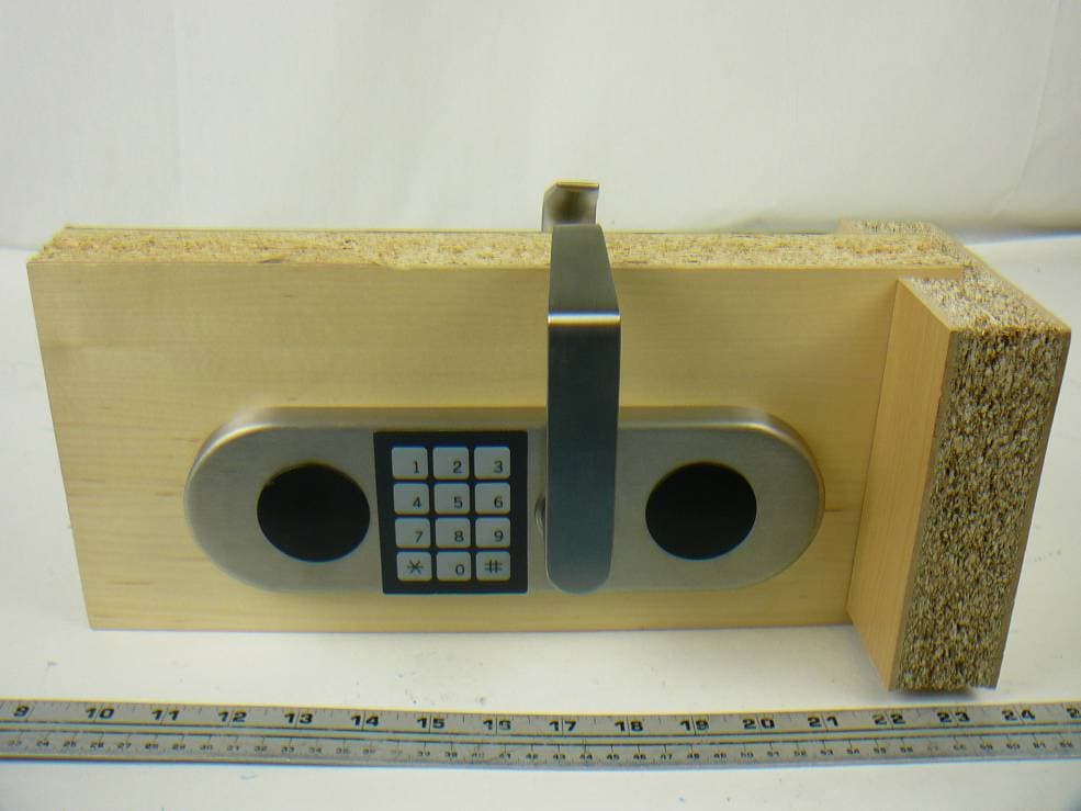
Y29SA-MDR
Aug 16, 2012Wireless Security Door Reader
Equipment Class
DSS - Part 15 Spread Spectrum Transmitter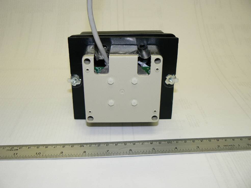
Y29SA-PWR-C
Jun 21, 2012Wireless Wall Reader Module
Equipment Class
DTS - Digital Transmission System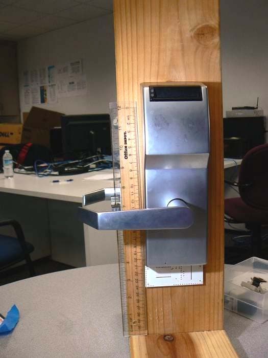
Y29SA-DR-1000
Dec 19, 2010Wireless, Hands-free Access Control and Tracking System
Equipment Class
DTS - Digital Transmission System
Y29SA-AP-200
Dec 19, 2010Wireless, Hands-free Access Control and Tracking System
Equipment Class
DTS - Digital Transmission System
Y29SA-UK-005
Dec 19, 2010Wireless, Hands-free Access Control and Tracking System
Equipment Class
DTS - Digital Transmission System