Y29SA-AP-200Wireless, Hands-free Access Control and Tracking System
SecureALL Corporation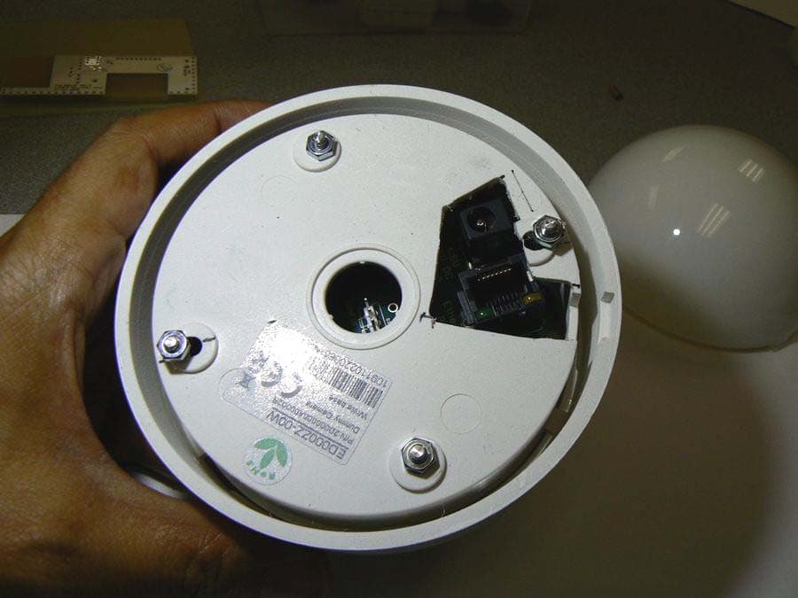
Click to zoom
Application Details
- Equipment Class
- DTS - Digital Transmission System
- Date of Grant
- Dec 19, 2010
- Application Purpose
- Original Equipment
- Date of Application
- Dec 19, 2010
- Equipment Note
- Wireless, Hands-free Access Control and Tracking System
- Frequency Range
- 2405.00000000 - 2475.00000000
- Company
- SecureALL Corporation
- Country
- United States
Documents & Files
Document Text
Text extracted from the exhibit documents filed with the FCC. Open a document above to read the original.
Users Manual
ROUTER INSTALLATION MANUAL As opposed to a user manual, this is an installation manual for the router unit, as there is no user interaction with this device. The first step in the installation process is to assess the floor plan of the building. This step is handled by the SecureALL staff. Once a preliminary assessment is made, a site survey is carried out, once again by the SecureALL staff, but usually accompanied by a member of the customer’s facilities or IT department. The purpose of the site survey is mount portable antennas at the recommended locations and measure signal strength at each portal that will have the SecureALL system installed. If there is any location in the building that has insufficient signal strength, either the antenna can be moved to a more optimum location or additional antennas can be provided to ensure complete coverage. Once router locations have been firmed up, it is necessary for the customer to run LAN lines to each router location, install each router dome package in a ceiling tile with the supplied plastic clips, connect the LAN cable to the router unit and connect the other end of the LAN to a POE port. POE supplies both data and power to the router. There are also rechargeable batteries installed on the router in the event of a power failure but these require no user interaction. Once the router is installed, the plug-and-play software that has been developed by SecureALL automatically starts communication between the router and the portals. FCC Caution: This device complies with part 15 of the FCC Rules. Operation is subject to the following two conditions: (1) This device may not cause harmful interference, and (2) This device must accept any interference received, including interference that may cause undesired operation Any Changes or modifications not expressly approved by the party responsible for compliance could void the user’s authority to operate this equipment.
Cover Letter(s)
SecureALL Corporation x 695 Woburn Court Mountain View, CA 94040 x (M) 650.704.2725 (F) 650.938.3755 FCC Confidential Authorization December 15, 2010 FEDERAL COMMUNICATIONS COMMISSION Authorization and Evaluation Division 7435 Oakland Mills Road Columbia, MD 21046 Subject: Confidentiality Request regarding application for certification of FCC ID: Y29SA-AP-200 In accordance with Sections 0.457 and 0.459 of the Commission’s Rules, SecureALL Corporation hereby requests confidential treatment of information accompanying this application as outlined below: Long Term: • Block Diagram • Schematics • Operation Description Short Term: • EUT External Photos • EUT Internal Photos The above materials contain proprietary and confidential information not customarily released to the public. The public disclosure of these materials provides unjustified benefits to its competitors in the market. Sincerely, Dr. Richard Schaffzin
External Photos
SecureALL Coropration FCC ID: Y29SA-AP-200 Report Number: R1012015-247 Page 50 of 53 FCC Part 15C Test Report 15 Exhibit C - EUT Photographs 15.1 EUT– Top View 15.2 EUT– Bottom View SecureALL Coropration FCC ID: Y29SA-AP-200 Report Number: R1012015-247 Page 51 of 53 FCC Part 15C Test Report 15.3 EUT AC/DC Adaptor View
ID Label/Location Info
SecureALL Coropration FCC ID: Y29SA-AP-200 Report Number: R1012015-247 Page 44 of 53 FCC Part 15C Test Report 13 Exhibit A - FCC Equipment Labeling Requirements 13.1 FCC ID Label Requirements As per FCC §2.925, (a) Each equipment covered in an application for equipment authorization shall bear a nameplate or label listing the following: (1) FCC Identifier consisting of the two elements in the exact order specified in §2.926. The FCC Identifier shall be preceded by the term FCC ID in capital letters on a single line, and shall be of a type size large enough to be legible without the aid of magnification. Example: FCC ID: XXX123 Where: XXX—Grantee Code 123—Equipment Product Code As per FCC §15.19, (a) In addition to the requirements in part 2 of this chapter, a device subject to certification, or verification shall be labeled as follows: (3) All other devices shall bear the following statement in a conspicuous location on the device: This device complies with part 15 of the FCC Rules. Operation is subject to the following two conditions: (1) This device may not cause harmful interference, and (2) this device must accept any interference received, including interference that may cause undesired operation. (4) Where a device is constructed in two or more sections connected by wires and marketed together, the statement specified above is required to be affixed only to the main control unit. If the EUT is integrated within another device then a label affixed to the host shall also state, “Contains FCC ID: XXXXXX” (5) When the device is so small or for such use that it is not practicable to place the statement specified under paragraph (a) of this section on it, the information required by this paragraph shall be placed in a prominent location in the instruction manual or pamphlet supplied to the user or, alternatively, shall be placed on the container in which the device is marketed. However, the FCC identifier or the unique identifier, as appropriate, must be displayed on the device. 13.2 FCC ID Label Contents Model: SA-AP-200 This device complies with part 15 of the FCC Rules. Operation is subject to the following two conditions: (1) This device may not cause harmful interference, and (2) this device must accept any interference received, including interference that may cause undesired operation. FCC ID: Y29SA-AP-200 SecureALL Corporation SecureALL Coropration FCC ID: Y29SA-AP-200 Report Number: R1012015-247 Page 45 of 53 FCC Part 15C Test Report 13.3 FCC ID Label Location on EUT Label here
Internal Photos
SecureALL Coropration FCC ID: Y29SA-AP-200 Report Number: R1012015-247 Page 52 of 53 FCC Part 15C Test Report 15.4 EUT Open Chassis View 15.5 EUT PCB Assembly Board - Top View SecureALL Coropration FCC ID: Y29SA-AP-200 Report Number: R1012015-247 Page 53 of 53 FCC Part 15C Test Report 15.6 EUT PCB Assembly Board – Bottom View 15.7 EUT PCB Assembly Board – Antenna View ***** END OF REPORT *****
RF Exposure Info
SecureALL Coropration FCC ID: Y29SA-AP-200 Report Number: R1012015-247 Page 9 of 53 FCC Part 15C Test Report 4 FCC §15.247(i) & §2.1091 - RF Exposure Information 4.1 Applicable Standard According to FCC §15.247(i) and §1.1307(b)(1), systems operating under the provisions of this section shall be operated in a manner that ensures that the public is not exposed to radio frequency energy level in excess of the Commission’s guidelines. Limits for General Population/Uncontrolled Exposure Frequency Range (MHz) Electric Field Strength (V/m) Magnetic Field Strength (A/m) Power Density (mW/cm 2 ) Averaging Time (minutes) Limits for General Population/Uncontrolled Exposure 0.3-1.34 614 1.63 *(100) 30 1.34-30 824/f 2.19/f *(180/f 2 ) 30 30-300 27.5 0.073 0.2 30 300-1500 / / f/1500 30 1500-100,000 / / 1.0 30 f = frequency in MHz * = Plane-wave equivalent power density 4.2 MPE Prediction Predication of MPE limit at a given distance, Equation from OET Bulletin 65, Edition 97-01 S = PG/4πR² Where: S = power density P = power input to antenna G = power gain of the antenna in the direction of interest relative to an isotropic radiator R = distance to the center of radiation of the antenna 4.3 MPE Results Maximum peak output power at antenna input terminal (dBm): 10.23 Maximum peak output power at antenna input terminal (mW): 10.544 Prediction distance (cm): 20 Prediction frequency (MHz): 2440 Maximum Antenna Gain, typical (dBi): 5.0 Maximum Antenna Gain (numeric): 3.162 Power density of prediction frequency at 20.0 cm (mW/cm 2 ): 0.00663 MPE limit for uncontrolled exposure at prediction frequency (mW/cm 2 ): 1.0 The device is compliant with the requirement MPE limit for uncontrolled exposure. The maximum power density at the distance of 20 cm is 0.00663mW/cm 2 .Limit is 1mW/cm 2 .
Test Setup Photos
SecureALL Coropration FCC ID: Y29SA-AP-200 Report Number: R1012015-247 Page 46 of 53 FCC Part 15C Test Report 14 Exhibit B - Test Setup Photographs 14.1 Radiated Emission below 1 GHz Front View @ 3 Meters 14.2 Radiated Emission below 1 GHz Rear View @ 3 Meters SecureALL Coropration FCC ID: Y29SA-AP-200 Report Number: R1012015-247 Page 47 of 53 FCC Part 15C Test Report 14.3 Radiated Emission above 1 GHz Front View @ 3 Meters 14.4 Radiated Emission above 1 GHz Front View @ 3 Meters SecureALL Coropration FCC ID: Y29SA-AP-200 Report Number: R1012015-247 Page 48 of 53 FCC Part 15C Test Report 14.5 AC Line Conducted Emission Front View - PoE 14.6 AC Line Conducted Emission Side View - PoE SecureALL Coropration FCC ID: Y29SA-AP-200 Report Number: R1012015-247 Page 49 of 53 FCC Part 15C Test Report 14.7 AC Line Conducted Emission Front View – Power AC/DC Adaptor 14.8 AC Line Conducted Emission Side View - Power AC/DC Adaptor
Contact Information
Applicant
Richard Schaffzin(CEO)
Test Firm
Bay Area Compliance LaboratoryJohn Chan
Technical Specifications
| # | Rule Parts | Frequency Range | Power Output |
|---|---|---|---|
| 1 | 15C | 2.40 GHz - 2.48 GHz | 10.50 mW |
Other Applications from SecureALL Corporation
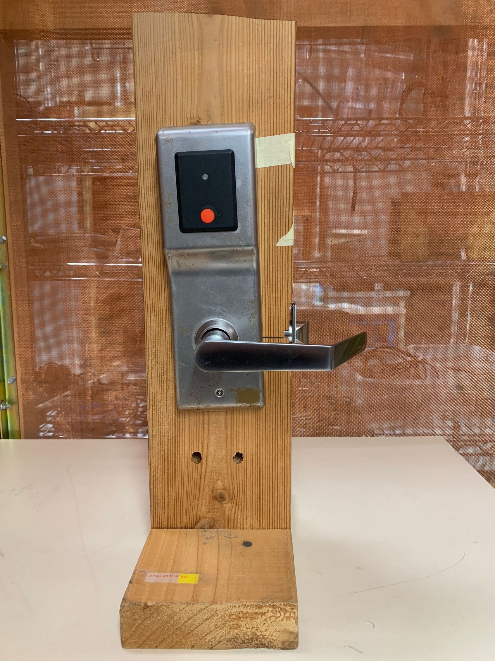
Y29-SA-ODL
May 13, 2020Wireless hands-free access control
Equipment Class
DTS - Digital Transmission System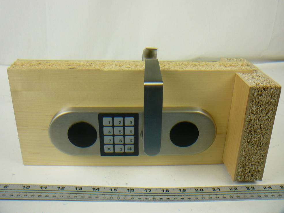
Y29SA-MDR
Aug 16, 2012Wireless Security Door Reader
Equipment Class
DSS - Part 15 Spread Spectrum Transmitter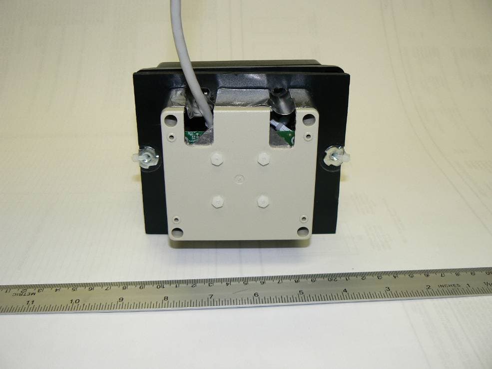
Y29SA-PWR-C
Jun 21, 2012Wireless Wall Reader Module
Equipment Class
DTS - Digital Transmission System
Y29SA-DR-1000
Dec 19, 2010Wireless, Hands-free Access Control and Tracking System
Equipment Class
DTS - Digital Transmission System
Y29SA-UK-005
Dec 19, 2010Wireless, Hands-free Access Control and Tracking System
Equipment Class
DTS - Digital Transmission System