Y38TE1211Emodlet gateway
ThinkEco, Inc.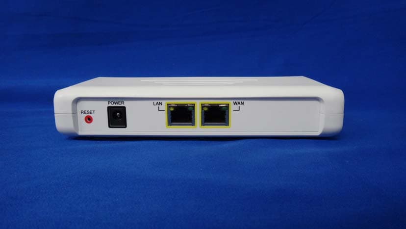
Click to zoom
Application Details
- Equipment Class
- DTS - Digital Transmission System
- Date of Grant
- Jun 19, 2013
- Application Purpose
- Original Equipment
- Date of Application
- Jun 19, 2013
- Equipment Note
- modlet gateway
- Frequency Range
- 2405.00000000 - 2475.00000000
- Company
- ThinkEco, Inc.
- Country
- United States
Documents & Files
Document Text
Text extracted from the exhibit documents filed with the FCC. Open a document above to read the original.
Users Manual
ThinkEco™ Products and Specifications For more information and to learn about your product(s) please read all user guide/manuals provided to you (in both paper and electronic form) including in the software downloaded in connection with the usage of these products and all operating and safety instructions. If you fail to do so the products listed below may not function properly and may lead to damage to the products and to other danger. modlet® Model Name: TE1010 Specifications • Electrical Rating: 125V~15A/60Hz/1875W • NEMA 5-15 • ZigBee (IEEE 802.15.4) wireless communication Important Safety Information: • Use indoors in a dry location. • Do not use this product in connection with critical care equipment (i.e. life-support systems). • Contains non-user serviceable parts; do not open. • This is a live AC outlet, even when the Modlet is in an “off scheduled mode”. • This product is not a toy. Do not allow children to operate it. • Not intended for use with loads rated above 15 Amps • Do not “daisy-chain” the Modlet. Only plug the Modlet into a duplex outlet or a grounded extension cord rated 15 Amps or higher. • In an over current condition or if the Modlet is plugged into an old and/or damaged socket the Modlet and socket temperature may increase substantially. Unplug the Modlet and appliances immediately and discontinue use. You should contact a qualified electrician to inspect and/or replace the outlet. Connecting a Modlet to an improperly grounded outlet will void all warranties. • UL 916 listed modletBN™ Model Name: TE4010 Specifications • Electrical Rating: 125V~15A/60Hz/1875W • NEMA 5-15 • ZigBee (IEEE 802.15.4) wireless communication Important Safety Information: • Use indoors in a dry location. • Do not use this product in connection with critical care equipment (i.e. life-support systems). • Contains non-user serviceable parts; do not open. • This is a live AC outlet, even when the Modlet is in an “off scheduled mode”. • This product is not a toy. Do not allow children to operate it. • Not intended for use with loads rated above 15 Amps • Do not “daisy-chain” the Modlet. Only plug the Modlet into a duplex outlet or a grounded extension cord rated 15 Amps or higher. • In an over current condition or if the Modlet is plugged into an old and/or damaged socket the Modlet and socket temperature may increase substantially. Unplug the Modlet and appliances immediately and discontinue use. You should contact a qualified electrician to inspect and/or replace the outlet. Connecting a Modlet to an improperly grounded outlet will void all warranties. • UL 916 listed Model Name: TE4011 Specifications • Electrical Rating: 125V~20A/60Hz/3000W • NEMA 5-20 • ZigBee (IEEE 802.15.4) wireless communication Important Safety Information: • Use indoors in a dry location. • Do not use this product in connection with critical care equipment (i.e. life-support systems). • Contains non-user serviceable parts; do not open. • This is a live AC outlet, even when the Modlet is in an “off scheduled mode”. • This product is not a toy. Do not allow children to operate it. • Not intended for use with loads rated above 20 Amps • Do not “daisy-chain” the Modlet. Only plug the Modlet into a duplex outlet or a grounded extension cord rated 20 Amps or higher. • In an over current condition or if the Modlet is plugged into an old and/or damaged socket the Modlet and socket temperature may increase substantially. Unplug the Modlet and appliances immediately and discontinue use. You should contact a qualified electrician to inspect and/or replace the outlet. Connecting a Modlet to an improperly grounded outlet will void all warranties. • UL 916 listed Model Name: TE4012 Specifications • Electrical Rating: 240V~15A/60Hz/3600W • NEMA 6-15 • ZigBee (IEEE 802.15.4) wireless communication Important Safety Information: • Use indoors in a dry location. • Do not use this product in connection with critical care equipment (i.e. life-support systems). • Contains non-user serviceable parts; do not open. • This is a live AC outlet, even when the Modlet is in an “off scheduled mode”. • This product is not a toy. Do not allow children to operate it. • Not intended for use with loads rated above 15 Amps • Do not “daisy-chain” the Modlet. Only plug the Modlet into a duplex outlet or a grounded extension cord rated 15 Amps or higher. • In an over current condition or if the Modlet is plugged into an old and/or damaged socket the Modlet and socket temperature may increase substantially. Unplug the Modlet and appliances immediately and discontinue use. You should contact a qualified electrician to inspect and/or replace the outlet. Connecting a Modlet to an improperly grounded outlet will void all warranties. • UL 916 listed Model Name: TE4013 Specifications • Electrical Rating: 240V~20A/60Hz/4800W • NEMA 6-20 • ZigBee (IEEE 802.15.4) wireless communication Important Safety Information: • Use indoors in a dry location. • Do not use this product in connection with critical care equipment (i.e. life-support systems). • Contains non-user serviceable parts; do not open. • This is a live AC outlet, even when the Modlet is in an “off scheduled mode”. • This product is not a toy. Do not allow children to operate it. • Not intended for use with loads rated above 20 Amps • Do not “daisy-chain” the Modlet. Only plug the Modlet into a duplex outlet or a grounded extension cord rated 20 Amps or higher. • In an over current condition or if the Modlet is plugged into an old and/or damaged socket the Modlet and socket temperature may increase substantially. Unplug the Modlet and appliances immediately and discontinue use. You should contact a qualified electrician to inspect and/or replace the outlet. Connecting a Modlet to an improperly grounded outlet will void all warranties. • UL 916 listed modlet® Gateway Model Name: TE1210 Specifications • AC/DC power supply: 100V-240V/50-60Hz/0.5A Max • Gateway device: 12V/1A • ZigBee (IEEE 802.15.4) wireless com…
Text truncated - open the document above for the full version.
Users Manual
Back View Hardware Top View Bottom View Wall mounts Front View WAN interface LED 3G LED (only on 3G model) ZigBee interface LED Power LED Error LED Run LED AC/DC power supply LAN connector Reset button WAN connector LAN interface LED LED light overview LED Status Identification Power On (Green) Power On RUN On (Green) POST is successful ERROR On (Red) POST fails ZigBee Off ZigBee is disabled On (Blue) ZigBee module is enabled Off No device is connected On (Orange) A 10/100 Mbps device is connected to the port Flashing (Orange) A 10/100 Mbps device is transmitting or receiving to the port On (Green) A 1000 Mbps device is connected to the port Ethernet WAN Port Link/ACT Flashing (Green) A 1000 Mbps device is transmitting or receiving to the port Off No device is connected On (Orange) A 10/100 Mbps device is connected to the port Flashing (Orange) A 10/100 Mbps device is transmitting or receiving to the port On (Green) A 1000 Mbps device is connected to the port Ethernet LAN Port Link/ACT Flashing (Green) A 1000 Mbps device is transmitting or receiving to the port Installation What you need to get started 1 power cord (included) 1 Ethernet cord (included) INSTRUCTIONS 1. Determine your gateway’s Ethernet Mac address Look on the bottom of your gateway for the Ethernet MAC address and write it down. 2. Plug in modlet gateway Plug in the modlet gateway into an electrical outlet using the power cord provided. The green power LED light should turn on. Then plug the gateway into your home or office router using the Ethernet cord provided. The WAN interface LED will be flashing and then become solid when connected. 3. Register a modlet account Go to https://mymodlet.com and select the link that says “New User? Create an Account”. Follow all on screen instructions to register an account. On the last screen, click the “I have a Gateway” button. Enter the Ethernet MAC ID for your Gateway (From step 1) If prompted enter “admin” for the username and “admin” for the password 4. Set up your modlet(s) Follow all on screen instructions to set up your modlet(s). Troubleshooting If you are connected to the internet and logged into your account, but you’re not seeing the latest data, try these tips. 1. Check gateway Make sure your gateway is correctly connected AC/DC adapter plugged in (POWER led ON) LAN cable plugged in (WAN led flashing) ZigBee module in operative mode (ZigBee led ON) Next restart gateway Restart gateway from Web GUI If not successful please: o press reset button and wait system restart If still not successful please: o unplug and replug AC/DC power supply Check the status of your gateway by clicking on the Modlet Network link in the top right of your screen and then clicking on USB Receiver. 2. Be patient When you first set up your network, or if your computer has been off for a while, the data may take a few minutes to load onto the interface. Check back in 15 minutes. 3. Refresh Try hitting the refresh button on the Energy Usage tab or your browser. 4. Verify parameters Check the variables you selected for the graph: does the start and end date match when you plugged in your modlet? Do you have at least one device selected? Click on the name of the devices you want to graph or select all to see total energy consumption. 5. Check devices Check the status of your devices on the energy usage tab. A green light next to your device means it has reported data to your computer in the last 24 hours. If the light is red, first restart you gateway. Next, verify your devices are labeled correctly and assigned to the correct outlet by clicking Modlet Network and then Modlets. For more troubleshooting information, call the modlet tech support center at 1-800-682-0152. Modlet® gateway PACKING LIST 1 modlet gateway TE1211E 1 Cable Ethernet, 6FT min 1 AC/DC Power supply, 110V/240V Input, 12V/1A output ThinkEco modlet® gateway Thank you for purchasing your new modlet® gateway! For more information and to learn about your modlet® gateway please visit www.themodlet.com. Please read all user guides/manuals provided to you (in both paper and electronic form) including in the software downloaded in connection with the usage of this device and all operating and safety instructions. If you fail to do so this product may not function properly and may lead to damage to the product and to other danger. modlet® gateway Specifications ZigBee (IEEE 802.15.4) wireless communication Power source: 12V DC Important Safety Information: Use indoors in a dry location. Contains non-user serviceable parts; do not open. This product is not a toy. Do not allow children to operate it. Regulatory Information: Installation and use of this device must be in strict accordance with the instructions included in the user documentation provided with the product or at www.thinkeco.com. Any changes or modifications made to this device that are not expressly approved by the manufacturer may void the user’s authority to operate the equipment. ThinkEco will assume no liability for any damage or violation of government regulations arising from failing to comply with these guidelines. RF Exposure Warning This equipment complies with FCC radiation exposure limits set forth for an uncontrolled environment. This equipment should be installed and operated with minimum distance of 7.9 inches (20cm) between the radiator and your body. This transmitter must not be co-located or operated in conjunction with any other antenna or transmitter. Note: USA-FCC (Federal Communications Commission) statement This device complies with Part 15 of FCC Rules. Operation is subject to the following two conditions: 1. This device may not cause interference, and 2. This device must accept any interference, including interference that may cause undesired operation of this device. Note: FCC Interference Statement This equipment has been tested and found to comply with the limits for a Class B digital device, pu…
Text truncated - open the document above for the full version.
External Photos
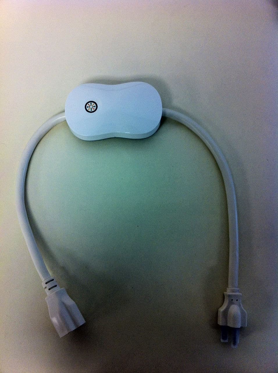
Report No.: 136036R-RFUSP42V01 Page : 1 of 14 Attachment 2 : EUT Detailed Photographs (1) EUT Photo (2) EUT Photo Report No.: 136036R-RFUSP42V01 Page : 2 of 14 (3) EUT Photo (4) EUT Photo
ID Label/Location Info
ThinkEco Inc. 148 Madison Avenue, 8th Floor, New York, NY, United States, 10016 Tel : 212-684-2959 IC Label ThinkEco Inc. 148 Madison Avenue, 8th Floor, New York, NY, United States, 10016 Tel : 212-684-2959 The IC Label will be placed on the equipment as shown in the photograph below.
ID Label/Location Info
ThinkEco Inc. FCC ID.: Y38TE1211E 148 Madison Avenue, 8th Floor, New York, NY, United States,10016.Tel : 212-684-2085 The FCC ID Label will be placed on the equipment as shown in the photograph below.
Internal Photos
Report No.: 136036R-RFUSP42V01 Page : 3 of 14 (5) EUT Photo (6) EUT Photo Antenna Report No.: 136036R-RFUSP42V01 Page : 4 of 14 (7) EUT Photo (8) EUT Photo Zigbee Module Report No.: 136036R-RFUSP42V01 Page : 5 of 14 (9) EUT Photo (10) EUT Photo Report No.: 136036R-RFUSP42V01 Page : 6 of 14 (11) EUT Photo (12) EUT Photo Report No.: 136036R-RFUSP42V01 Page : 7 of 14 (13) EUT Photo (Zigbee Module) (14) EUT Photo (Zigbee Module) Report No.: 136036R-RFUSP42V01 Page : 8 of 14 (15) EUT Photo (Zigbee Module) (16) EUT Photo (Zigbee Module) Report No.: 136036R-RFUSP42V01 Page : 9 of 14 (17) EUT Photo (18) EUT Photo Report No.: 136036R-RFUSP42V01 Page : 10 of 14 (19) EUT Photo (20) EUT Photo Report No.: 136036R-RFUSP42V01 Page : 11 of 14 (21) EUT Photo (Antenna) (22) EUT Photo (Antenna) Report No.: 136036R-RFUSP42V01 Page : 12 of 14 (23) EUT Photo (24) EUT Photo Report No.: 136036R-RFUSP42V01 Page : 13 of 14 (25) EUT Photo (26) EUT Photo Report No.: 136036R-RFUSP42V01 Page : 14 of 14 (27) EUT Photo
RF Exposure Info
Report No. 136036R-RFUSP42V01 Page: 1 of 3 RF Exposure Evaluation declaration Product Name modlet gateway Model No. TE1211E FCC ID Y38TE1211E Applicant ThinkEco Inc. Address 148 Madison Avenue, 8th Floor, New York, NY, United States,10016 Date of Receipt May 28. 2013 Date of Declaration June 04, 2013 Report No. 136036R-RFUSP42V01 The declaration results relate only to the samples calculated. The declaration shall not be reproduced except in full without the written approval of QuieTek Corporation. This report must not be used to claim product endorsement by NVLAP any agency of the U.S. Government Report No. 136036R-RFUSP42V01 Page: 2 of 3 1. RF Exposure Evaluation 1.1. Limits According to FCC 1.1310: The criteria listed in the following table shall be used to evaluate the environment impact of human exposure to radio frequency (RF) radiation as specified in 1.1307(b) LIMITS FOR MAXIMUM PERMISSIBLE EXPOSURE (MPE) Frequency Range (MHz) Electric Field Strength (V/m) Magnetic Field Strength (A/m) Power Density (mW/cm 2 ) Average Time (Minutes) (A) Limits for Occupational/ Control Exposures 300-1500 -- -- F/300 6 1500-100,000 -- -- 5 6 (B) Limits for General Population/ Uncontrolled Exposures 300-1500 -- -- F/1500 6 1500-100,000 -- -- 1 30 F= Frequency in MHz Friis Formula Friis transmission formula: Pd = (Pout*G)/(4*pi*r 2 ) Where Pd = power density in mW/cm 2 Pout = output power to antenna in mW G = gain of antenna in linear scale Pi = 3.1416 R = distance between observation point and center of the radiator in cm Pd id the limit of MPE, 1 mW/cm 2 . If we know the maximum gain of the antenna and the total power input to the antenna, through the calculation, we will know the distance r where the MPE limit is reached. 1.2. Test Procedure Software provided by client enabled the EUT to transmit and receive data at lowest, middle and highest channel individually. The temperature and related humidity: 18°Cand 78% RH. Report No. 136036R-RFUSP42V01 Page: 3 of 3 1.3. Test Result of RF Exposure Evaluation Product : modlet gateway Test Item : RF Exposure Evaluation Test Site : No.3 OATS Operation Frequency 2405~2475MHz Maximum Conducted output power 2.78dBm Antenna gain 2.69dBi Output Power Into Antenna & RF Exposure Evaluation Distance: Output Power to Antenna (mW) Power Density at R = 20 cm (mW/cm2) 1.8967 0.000701 Power density in column 4 is much lower than the limit (1 mW/cm 2 ).
Test Report
Report No. 136036R-RFUSP42V01 Page : 1 of 49 FCC Test Report Product Name modlet gateway Model No TE1211E FCC ID. Y38TE1211E Applicant ThinkEco Inc. Address 148 Madison Avenue, 8th Floor, New York, NY, United States,10016 Date of Receipt May 28, 2013 Issue Date June 18, 2013 Report No. 136036R-RFUSP42V01 Report Version V1.0 The test results relate only to the samples tested. The test report shall not be reproduced except in full without the written approval of QuieTek Corporation. This report must not be used to claim product endorsement by NVLAP any agency of the U.S. Government Report No. 136036R-RFUSP42V01 Page : 2 of 49 Test Report Certification Issue Date: June 18, 2013 Report No.: 136036R-RFUSP42V01 Product Name modlet gateway Applicant ThinkEco Inc. Address 148 Madison Avenue, 8th Floor, New York, NY, United States,10016 Manufacturer DONG GUAN G-COM COMPUTER CO., LTD. Model No. TE1211E EUT Rated Voltage AC 100-240V/50-60Hz EUT Test Voltage AC 120V/ 60Hz Trade Name ThinkEco Inc. Applicable Standard FCC CFR Title 47 Part 15 Subpart C: 2012 ANSI C63.4: 2003, ANSI C63.10: 2009 Test Result Complied The test results relate only to the samples tested. The test report shall not be reproduced except in full without the written approval of QuieTek Corporation. This report must not be used to claim product endorsement by NVLAP any agency of the U.S. Government Documented By : ( Senior Adm. Specialist / Genie Chang ) Tested By : ( Assistant Engineer / Nowal Kuo ) Approved By : ( Manager / Vincent Lin ) Report No. 136036R-RFUSP42V01 Page : 3 of 49 TABLE OF CONTENTS Description Page 1. GENERAL INFORMATION .....................................................................................................5 1.1. EUT Description............................................................................................................................5 1.2. Operational Description ................................................................................................................7 1.3. Tested System Details....................................................................................................................8 1.4. Configuration of Tested System ....................................................................................................8 1.5. EUT Exercise Software .................................................................................................................8 1.6. Test Facility ...................................................................................................................................9 2. Conducted Emission..................................................................................................................10 2.1. Test Equipment............................................................................................................................10 2.2. Test Setup ....................................................................................................................................10 2.3. Limits ..........................................................................................................................................11 2.4. Test Procedure .............................................................................................................................11 2.5. Uncertainty ..................................................................................................................................11 2.6. Test Result of Conducted Emission.............................................................................................12 3. Peak Power Output ...................................................................................................................14 3.1. Test Equipment............................................................................................................................14 3.2. Test Setup ....................................................................................................................................14 3.3. Limits ..........................................................................................................................................14 3.4. Test Procedure .............................................................................................................................14 3.5. Uncertainty ..................................................................................................................................14 3.6. Test Result of Peak Power Output...............................................................................................15 4. Radiated Emission .....................................................................................................................16 4.1. Test Equipment............................................................................................................................16 4.2. Test Setup ....................................................................................................................................17 4.3. Limits ..........................................................................................................................................18 4.4. Test Procedure .............................................................................................................................18 4.5. Uncertainty ..................................................................................................................................19 4.6. Test Result of Radiated Emission................................................................................................20 5. RF antenna conducted test........................................................................................................24 5.1. Test Equipment............................................................................................................................24 5.2. Test Setup ..........................................…
Text truncated - open the document above for the full version.
Test Setup Photos
Report No.: 136036R-RFUSP42V01 Page : 1 of 3 Attachment 1: EUT Test Setup Photographs Front View of Conducted Test Back View of Conducted Test Report No.: 136036R-RFUSP42V01 Page : 2 of 3 Front View of Radiated Test Back View of Radiated Test Report No.: 136036R-RFUSP42V01 Page : 3 of 3 Front View of Radiated Test (Horn) Back View of Radiated Test (Horn)
Contact Information
Applicant
Peter Mayer(VP R&D)
Technical Contact
QuieTek CorporationSabina Chen
[email protected]886-2-8601-3788
No. 5-22, Rueishu Keng, Linkou Dist., · New Taipei City · Taiwan
Test Firm
DEKRA Testing and Certification Co., Ltd.Sky Hsu
Technical Specifications
| # | Rule Parts | Frequency Range | Power Output |
|---|---|---|---|
| 1 | 15C | 2.40 GHz - 2.48 GHz | 1.90 mW |
Other Applications from ThinkEco, Inc.
Y38TE5010
May 18, 2014TE5010, TE5011, TE5012, TE5013
Equipment Class
DTS - Digital Transmission System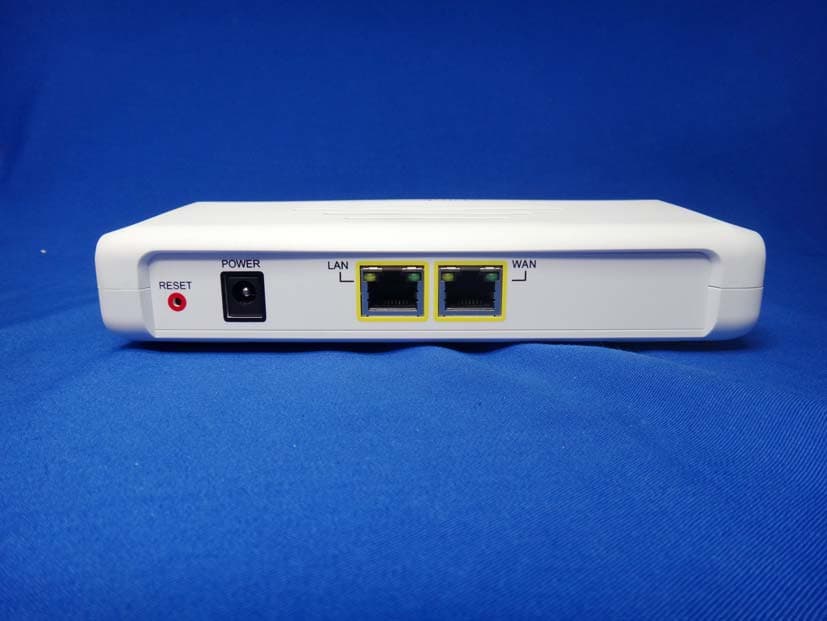
Y38TE1211M
Oct 23, 2013modlet gateway
Equipment Class
PCB - PCS Licensed Transmitter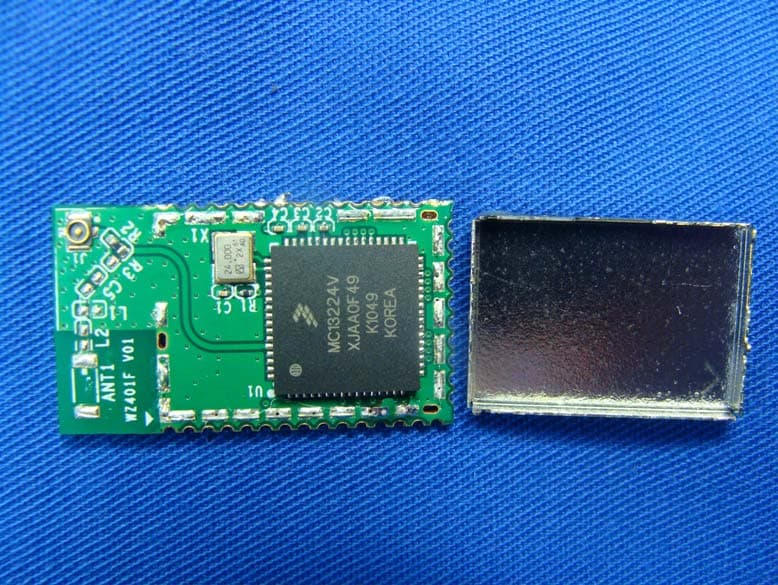
Y38TE7010
Mar 21, 2013modlet IQ
Equipment Class
DTS - Digital Transmission System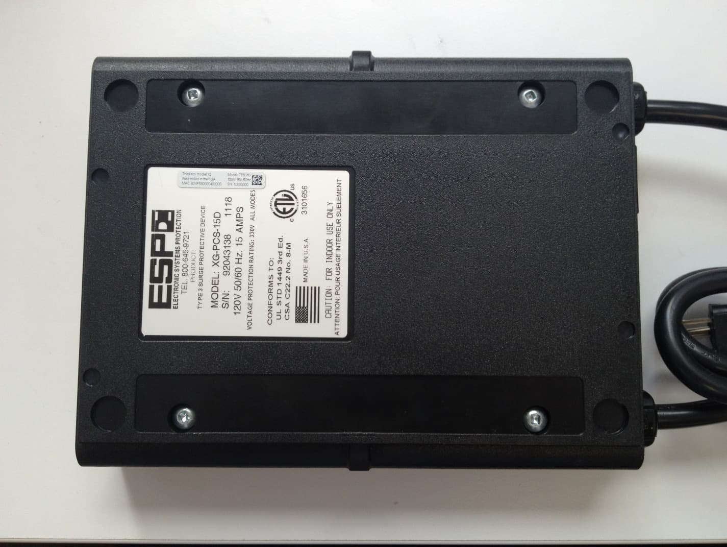
Y38TE6010
Jan 28, 2013TE6010
Equipment Class
DTS - Digital Transmission System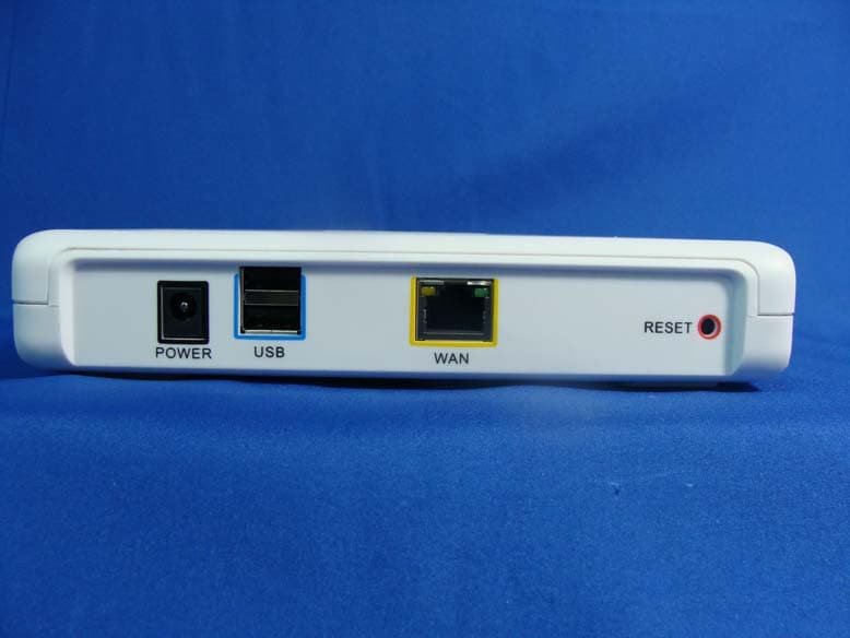
Y38TE1210
Apr 19, 2012modlet gateway
Equipment Class
DTS - Digital Transmission System