Y38TE6010TE6010
ThinkEco, Inc.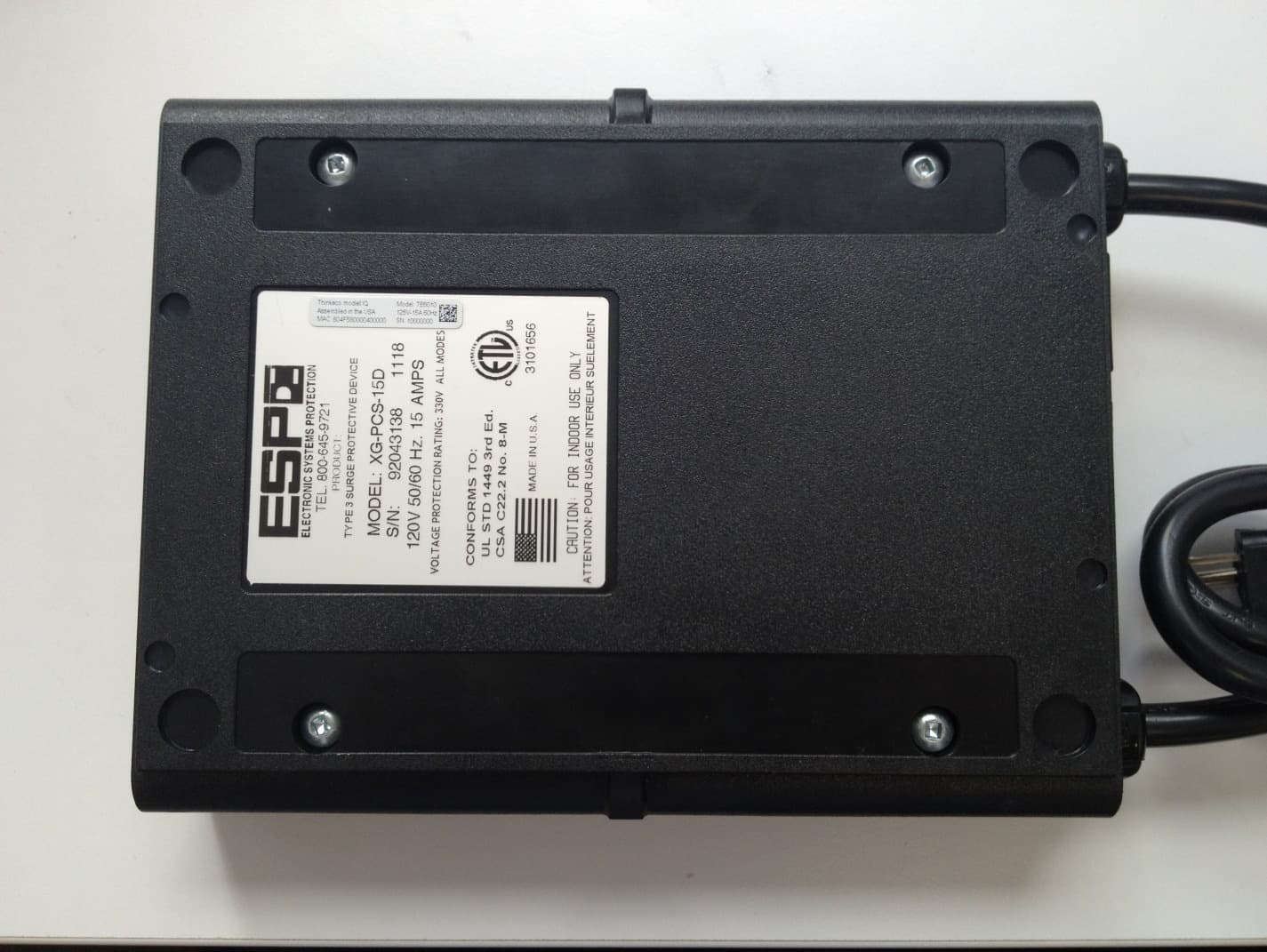
Click to zoom
Application Details
- Equipment Class
- DTS - Digital Transmission System
- Date of Grant
- Jan 28, 2013
- Application Purpose
- Original Equipment
- Date of Application
- Jan 28, 2013
- Equipment Note
- TE6010
- Frequency Range
- 2405.00000000 - 2480.00000000
- Company
- ThinkEco, Inc.
- Country
- United States
Documents & Files
Document Text
Text extracted from the exhibit documents filed with the FCC. Open a document above to read the original.
Users Manual
® User Guide Why use a modlet? Homes and offices now have more plugged-in devices than ever before, and the number is growing. These plugged-in devices make up 50% of home electricity bills and more than 20% of commercial energy bills! And much of this energy consumption occurs when devices are unused or off. A cable box uses almost as much energy when it’s off as when it’s on. So what’s the point of the “off” button then? The modlet helps you take control of your plug load energy consumption by allowing you to see how much energy each device consumes and then automatically schedule when devices are on or off. Implementing schedules with the modlet system is easy and your savings are clearly displayed via ThinkEco’s Web app – which is accessible through your computer or mobile device. Start saving now! For more information on how the modlet saves you energy, visit our website: www.themodlet.com Hardware The modlet plugs directly into any dual socket 3-pin outlet. The modlet’s integrated intelligence tracks energy consumption and wirelessly transmits the data to your computer through the USB receiver. modlet USB receiver Red LED indicator light Outlet 1 Outlet 2 Modlet Button Quick setup Go to www.mymodlet.com to create an account and begin the installation. Enter the registration key found on the inside cover of the modlet box. Create a user profile and then download and save the installer to your desktop. Double click on the installer icon to begin the wizard and follow the onscreen instructions. If required to reboot during the pr ocess, click back on the ThinkEco Installer to continue the installation. 1. Software 2. Hardware Plug your USB receiver into your computer when prompted by the Installer. Depending on your computer, you may see some ‘found new hardware’ or ‘install new hardware’ prompts. If so, be sure to accept all of them. If the USB receiver is not found on your first try, reinsert into the USB slot and push it in all the way. Turn off and unplug the electronic device closest to your computer that you want to monitor. Click ‘Search’ on the Installer first, then plug the modlet into the outlet. The spinning LED light will stop when your modlet joins the network. Plug your electronic device back into the modlet and complete the set up on the Installer. 4. Optional - Add more modlets More modlets can be added at any time. To do so, right click on the ThinkEco Icon in your computer tray and select Open Modlet Manager. Then click the Add Modlet button first, and then plug your next modlet into an outlet so it can join the n etwork. To build robust wireless networks, it’s best to work your way outward from your PC. Finish setting up your account and then start viewing your energy consumption through the Energy Usage tab. Keep in mind that it may take a few minutes after setting up your modlet to begin seeing data. To set a schedule, visit the Savings Plan tab to control when your devices are on and off. Please note, during the initial baseline period scheduling is not available. To view your account from any computer simply visit www.mymodlet.com or download the ThinkEco App for Android or iPhone. 3. Monitor & Control Troubleshooting If you are connected to the internet and logged into your account, but you’re not seeing the latest data, try these tips. 1. Check USB • Make sure your USB receiver is plugged in all the way. • Next unplug it and then plug it back into your computer. • Check the status of your USB by clicking on the Modlet Network link in the top right of your screen and then clicking on USB Receiver. 2. Be patient • When you first set up your network, or if your computer has been off for a while, the data may take a few minutes to load onto the interface. Check back in 15 minutes. 3. Refresh • Try hitting the refresh button on the Energy Usage tab or your browser. 4. Verify parameters • Check the variables you selected for the graph: does the start and end date match when you plugged in your modlet? • Do you have at least one device selected? Click on the name of the devices you want to graph or select all to see total energy consumption. 5. Check devices • Check the status of your devices on the energy usage tab. A green light next to your device means it has reported data to your computer in the last 24 hours. • If the light is red, first unplug and re-plug in your USB receiver. Next, verify your devices are labeled correctly and assigned to the correct outlet by clicking Modlet Network and then Modlets. For more troubleshooting information, call the modlet tech support center at 1-800-682-0152. Software tips Displays total power consumption for all devices as well as individual power traces for up to 5 devices at a time. 1. Energy Usage Customize the time period displayed on the graph View up to 5 individual power traces as separate lines or the total power consumption for more than 5 devices Click and drag your mouse across a section of the graph to zoom in Click on the names of one or more devices to display their consumption on the graph Export current data displayed to a file for more analysis Allows you to set up schedules for turning devices on and off. Choose from a template plan or create your own custom plan. This feature is available after the initial two-week baseline period.* 2. Savings Plans *The default setting for the baseline period is the first two weeks after you set up your modlets. The baseline period monitors the typical energy consumption of your devices. This information helps you create plans and calculate savings. You can create more than one plan – such as one for week- days and one for weekends View an overview of the schedules planned for today Create a plan for as little as one day or for many years Select days and times for your device to turn on Select which devices the plan applies to. You can create a separate plan for each device View total energy consumed and saved for all the devices in your Modlet Network. Check the status o…
Text truncated - open the document above for the full version.
Block Diagram
MC1322x Introduction MC1322x Reference Manual, Rev. 1.4 Freescale Semiconductor1-3 1.1Features This section provides a simplified block diagram and highlights MC1322x features. 1.1.1Block Diagram Figure 1-2 shows a simplified block diagram of the MC1322x. Figure 1-2. MC1322x Simplified Block Diagram 1.1.2Features Summary •IEEE 802.15.4 standard compliant on-chip transceiver/modem — 2.4GHz — 16 selectable channels — Programmable transmitter output power (-30 dBm to +4 dBm typical) — World-class receiver sensitivity – < -96 dBm typical receiver sensitivity using DCD mode (<1% PER, 20-byte packets) – < -100 dBm typical receiver sensitivity using NCD mode (<1% PER, 20-byte packets) •Hardware acceleration for IEEE 802.15.4 applications — MAC accelerator (sequencer and DMA interface) — Advanced encryption/decryption hardware engine (AES 128-bit) •Supports standard IEEE 802.15.4 signalling with 250 kbps data rate •32-bit ARM7TDMI-S CPU core with programmable performance up to 26 MHz (24 MHz typical) •Extensive on-board memory resources TIMER MODULE (TMR) (4 Tmr Blocks) UART MODULE (UART0) UART MODULE (UART1) SYNC SERIAL INTERFACE (SSI/i2S) KEYBOARD INTERFACE (KBI) INTER-IC BUS MODULE (I2C) SERIAL PERIPHERAL INTERFACE (SPI) DUAL 12-BIT ADC MODULE GPIO and IO CONTROL UP TO 64 IO PINS ARM7 TDMI-S 32-BIT CPU BUS INTERFACE & MEMORY ARBITRATOR ARM INTERRUPT CONTROLLER (AITC) JTAG/ Nexus DEBUG ADVANCED SECURITY MODULE (ASM) CLOCK & RESET MODE (CRM) RADIO INTERFACE MODULE (RIF) 96KBYTE SRAM (24K WORDS x 32 BITS) 80KBYTE ROM (20KWORDS x 32 BITS) RF OSCILLATOR & CLOCK GENERATION SPI FLASH MODULE (SPIF) 802.15.4 MAC ACCELERATOR (MACA) DIGITAL MODEM TX MODEM RX MODEM 128KBYTE NON-VOLATILE MEMORY (SERIAL FLASH) ANALOG TRANSMITTER ANALOG RECEIVER RF TX/RX SWITCH IEEE 802.15.4 TRANSCEIVER BALUN ANALOG POWER MANAGEMENT & VOLTAGE REGULATION MC1322x System on Chip Ext PLL Filter 24 MHz 32.768 KHz (optional) BATTERY DETECT
Cover Letter(s)
WTD 12.7.3 FCC Compliance Opinion THKE0020 Information about the Applicant Grantee (Company Name) ThinkEco, Inc. FCC Contact Person Ben Burns Address 148 Madison Avenue, 8th Floor City, State, Zip New York, NY 10016 Job Number THKE0020 Model TE6010 FCC ID Y38TE6010 Agent Approval Type Original Equipment Class DTS Digital Transmission System Rule Part 15.247 Overview The model TE6010 (Modlet IQ ESP) is designed to be an energy saving device, which is capable of remote switching appliances and measuring power consumption. The device works in tandem with a USB Receiver, which, together with a computer and software, forms a wireless network compliant with the ZigBee protocol. This network allows devices within range to communicate with the computer for purposes of monitoring and controlling appliances for energy savings. Confidentiality requested for allowed files. Request is properly addressed and referenced. Recommendation All items have been resolved and completed to my satisfaction; therefore I recommend this application for approval. Signature Dave Tolman, TCB Committee 10/12/2012
ID Label/Location Info
Label pictured in one of several possible final label locations, indicated by blue rectangles.
Operational Description
Antenna Info – TE6010 As shown in the photograph below, the modlet uses a permanently affixed monopole copper trace F-antenna which is inaccessible to the user, as the PCB is encased within the plastic housing. The Freescale MC1322x chip limits power to 3 dBm. The antenna is a 50 Ohm copper trace F-antenna with an approximately uniform radiation pattern and a peak gain of 2dBi. Radio Trace Antenna
RF Exposure Info
Compliance with 47 CFR 15.247(i) “Systems operating under the provisions of this section shall be operated in a manner that ensures that the public is not exposed to radio frequency energy levels in excess of the Commission's guidelines. See § 1.1307(b)(1) of this chapter.” The EUT contains an 802.15.4 Zigbee transceiver. The device would normally be considered a mobile transmitter per 47 CFR 2.1091 because it is designed to be used in other than fixed locations and to generally be used in such a way that a separation distance of at least 20 centimeters is normally maintained between the transmitter's radiating structure(s) and the body of the user or nearby persons. However there is nothing to prevent a user from placing the device within 20 cm of the user’s torso. In that case, it would be considered a portable device per 47 CFR 2.1093. The antenna is a permanently affixed monopole copper trace F-antenna with 2.0 dBi of gain. The maximum peak conducted output power is 2.13 mW. The maximum peak radiated power is 3.7 mW eirp for FCC ID: Y38TE6010. The transmit frequency is 2405 to 2480MHz, therefore the EUT does not require routine SAR evaluation because it falls below the low power threshold of 60/f(GHz)mW. Please see this excerpt from KDB 447498D01 Mobile Portable RF Exposure v04, item 2)(a)(i): "a device may be used in portable exposure conditions with no restrictions on host platforms when either the source-based time-averaged output power is <=60/f(GHz)mW or all measured 1-g SAR are <0.4W.kg." The applicant’s wireless radio, FCC ID: Y38TE6010, is compliant with the requirements of FCC 15.247(i).
Test Report
ThinkEco, Inc. Modlet IQ ESP Model TE6010 Report #: THKE0020 Report Prepared By Northwest EMC Inc. NORTHWEST EMC – (888) 364-2378 – www.nwemc.com California – Minnesota – Oregon – New York – Washington WTD 12.5.23 CERTIFICATE OF TEST Last Date of Test: August 13, 2012 ThinkEco, Inc. Model: Modlet IQ ESP Emissions Test Description Specification Test Method Pass/Fail Duty Cycle FCC 15.247:2012 ANSI C63.10:2009 Pass Output Power FCC 15.247:2012 ANSI C63.10:2009 Pass Spurious Radiated Emissions FCC 15.247:2012 ANSI C63.10:2009 Pass AC Powerline Conducted Emissions FCC 15.207:2012 ANSI C63.10:2009 Pass Spurious Conducted Emissions FCC 15.247:2010 ANSI C63.10:2009 Pass Power Spectral Density FCC 15.247:2010 ANSI C63.10:2009 Pass Occupied Bandwidth FCC 15.247:2010 ANSI C63.10:2009 Pass Band Edge Compliance FCC 15.247:2010 ANSI C63.10:2009 Pass Deviations From Test Standards None Approved By: Tim O'Shea, Operations Manager NVLAP Lab Code: 200676-0 Test Facility The measurement facility used to collect the data is located at: Northwest EMC, Inc. 41 Tesla Ave. Irvine, CA 92618 Phone: (503) 844-4066 Fax: 844-3826 This site has been fully described in a report filed with and accepted by the FCC (Federal Communications Commission) and Industry Canada (Site filing #2834B-1). This report must not be used to claim product certification, approval, or endorsement by NVLAP, NIST, or any agency of the federal government of the United States of America. Product compliance is the responsibility of the client, therefore the tests and equipment modes of operation represented in this report were agreed upon by the client, prior to testing. This Report may only be duplicated in its entirety. The results of this test pertain only to the sample(s) tested. The specific description is noted in each of the individual sections of the test report supporting this certificate of test. REV 2012.08.02 REVISION HISTORY Revision Number Description Date Page Number 00 None Barometric Pressure The recorded barometric pressure has been normalized to sea level. REV 2012.05.24 ACCREDITATIONS AND AUTHORIZATIONS United States FCC - Designated by the FCC as a Telecommunications Certification Body (TCB). Certification chambers, Open Area Test Sites, and conducted measurement facilities are listed with the FCC. A2LA - Accredited by A2LA to ISO / IEC Guide 65 as a product certifier. This allows Northwest EMC to certify transmitters to FCC and IC specifications. NVLAP - Each laboratory is accredited by NVLAP to ISO 17025 Canada IC - Recognized by Industry Canada as a Certification Body (CB). Certification chambers and Open Area Test Sites are filed with IC. European Union European Commission – Validated by the European Commission as a Conformity Assessment Body (CAB) under the EMC directive and as a Notified Body under the R&TTE Directive. Australia/New Zealand ACMA - Recognized by ACMA as a CAB for the acceptance of test data. Korea KCC / RRA - Recognized by KCC’s RRA as a CAB for the acceptance of test data. Japan VCCI - Associate Member of the VCCI. Conducted and radiated measurement facilities are registered. Taiwan BSMI – Recognized by BSMI as a CAB for the acceptance of test data. NCC - Recognized by NCC as a CAB for the acceptance of test data. Singapore IDA – Recognized by IDA as a CAB for the acceptance of test data. Hong Kong OFTA – Recognized by OFTA as a CAB for the acceptance of test data. Vietnam MIC – Recognized by MIC as a CAB for the acceptance of test data. Russia GOST – Accredited by Certinform VNIINMASH, CERTINFO, SAMTES, and Federal CHEC to perform EMC and Hygienic testing for Information Technology products to GOST standards. SCOPE For details on the Scopes of our Accreditations, please visit: http://www.nwemc.com/accreditations/ REV 2012.08.03 LOCATIONS Oregon Labs EV01-EV12 22975 NW Evergreen Pkwy, #400 Hillsboro, OR 97124 (503) 844-4066 California Labs OC01-OC13 41 Tesla Irvine, CA 92618 (949) 861-8918 New York Labs WA01-WA04 4939 Jordan Rd. Elbridge, NY 13060 (315) 685-0796 Minnesota Labs MN01-MN08 9349 W Broadway Ave. Brooklyn Park, MN 55445 (763) 425-2281 Washington Labs SU01-SU07 14128 339 th Ave. SE Sultan, WA 98294 (360) 793-8675 VCCI A-0108 A-0029 A-0109 A-0110 Industry Canada 2834D-1, 2834D-2 2834B-1, 2834B-2, 2834B-3 2834E-1 2834C-1 WTD 12.5.23 PRODUCT DESCRIPTION Client and Equipment Under Test (EUT) Information Company Name: ThinkEco, Inc. Address: 148 Madison Avenue, 8th Floor City, State, Zip: New York, NY 10016 Test Requested By: Peter Mayer Model: Modlet IQ ESP (Model TE6010) First Date of Test: August 18, 2011 Last Date of Test: August 13, 2012 Receipt Date of Samples: August 18, 2011 for Model TE1010; August 06, 2012 for Model TE6010 Equipment Design Stage: Production Equipment Condition: No Damage Information Provided by the Party Requesting the Test Functional Description of the EUT (Equipment Under Test): Power conditioning system Testing Objective: To demonstrate compliance on a Zigbee radio to FCC 15.247 requirements for the tests listed within FCC 15.247 requirements. The direct connect testing was completed with Model TE1010. This device contains the same radio as Model TE6010 and has the same direct connect characteristics. WTD 12.5.23 CONFIGURATIONS Configuration THKE0020- 1 EUT Description Manufacturer Model/Part Number Serial Number Power conditioning system ThinkEco, Inc. Modlet IQ ESP None Cables Cable Type Shield Length (m) Ferrite Connection 1 Connection 2 AC Power No 0.9m No Power conditioning system AC Mains RJ-14 No 2.15m No Power conditioning system Unterminated CAT-5e No 2.0m No Power conditioning system Unterminated AC Power No 1.8m No Power conditioning system Unterminated PA = Cable is permanently attached to the device. Shielding and/or presence of ferrite may be unknown. Configuration THKE0020- 2 EUT Description Manufacturer Model/Part Number Serial Number Power conditioning system ThinkEco, Inc. Modlet IQ ESP None Cables Cable Type Shield Length (m) Ferrite Connection 1 …
Text truncated - open the document above for the full version.
Test Setup Photos
Duty Cycle XMit 2012.07.31 NORTHWEST Duty Cycle PsaTx 2012.05.24 EMC SAM_1026.JPG Duty Cycle Output Power XMit 2012.07.31 NORTHWEST Output Power PsaTx 2012.05.24 EMC SAM_1026.JPG Output Power photo SAM_1027.JPG SAM_1029.JPG SPURIOUS RADIATED EMISSIONS PSA-ESCI 2012.08.08 photo SAM_1030.JPG SPURIOUS RADIATED EMISSIONS PSA-ESCI 2012.08.08 photo CE THKE0020 002.JPG CE THKE0020 001.JPG AC POWERLINE CONDUCTED EMISSIONS PSA-ESCI 2012.05.07 NORTHWEST EMC EV06 001.JPG EV06 002.JPG Occupied Bandwidth XMit 2011.08.04 NORTHWEST EMC EV06 001.JPG EV06 002.JPG Band Edge Compliance XMit 2011.08.04 NORTHWEST EMC EV06 001.JPG EV06 002.JPG Spurious Conducted Emissions XMit 2011.08.04 NORTHWEST EMC EV06 001.JPG EV06 002.JPG Power Spectral Density XMit 2011.08.04
Contact Information
Applicant
Peter Mayer(VP R&D)
Test Firm
Northwest EMC, Inc.Greg Kiemel
Technical Specifications
| # | Rule Parts | Frequency Range | Power Output |
|---|---|---|---|
| 1 | 15C | 2.40 GHz - 2.48 GHz | 2.13 mW |
Other Applications from ThinkEco, Inc.
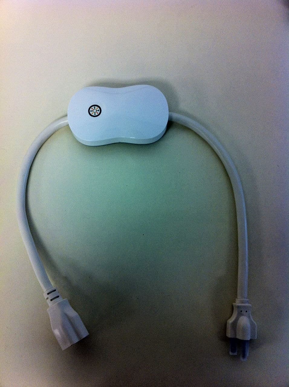
Y38TE5010
May 18, 2014TE5010, TE5011, TE5012, TE5013
Equipment Class
DTS - Digital Transmission System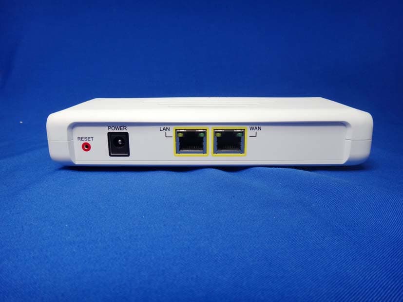
Y38TE1211M
Oct 23, 2013modlet gateway
Equipment Class
PCB - PCS Licensed Transmitter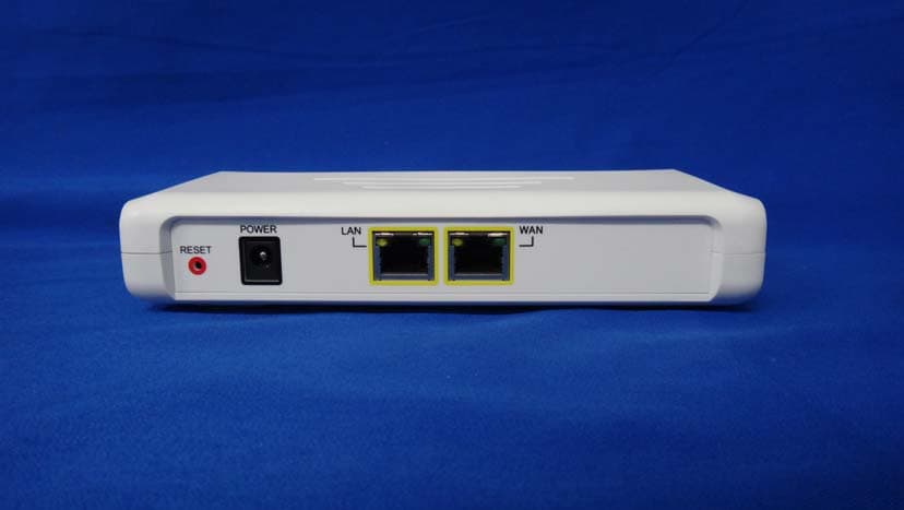
Y38TE1211E
Jun 19, 2013modlet gateway
Equipment Class
DTS - Digital Transmission System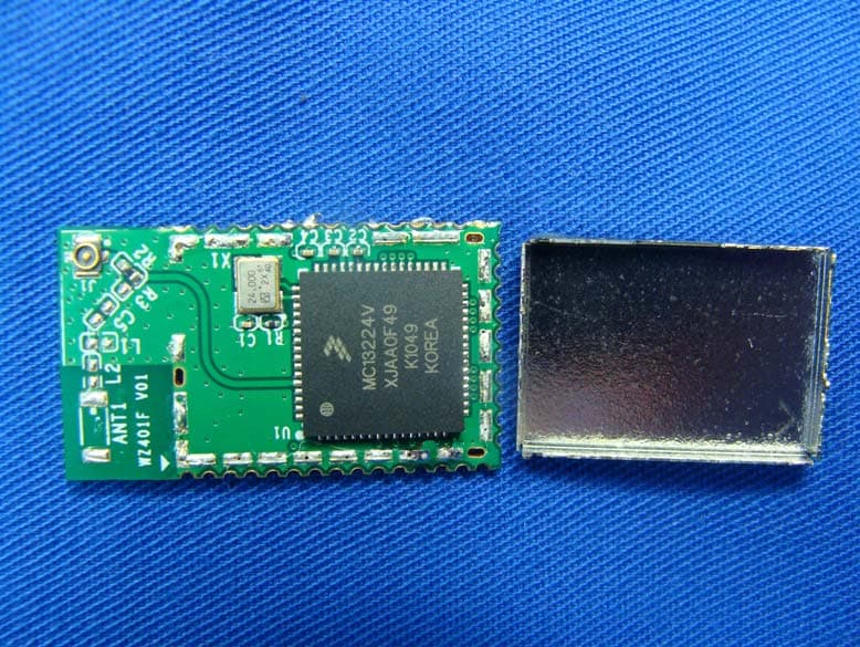
Y38TE7010
Mar 21, 2013modlet IQ
Equipment Class
DTS - Digital Transmission System
Y38TE1210
Apr 19, 2012modlet gateway
Equipment Class
DTS - Digital Transmission System