Y38TE5010TE5010, TE5011, TE5012, TE5013
ThinkEco, Inc.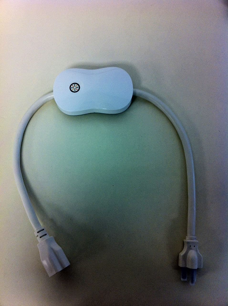
Click to zoom
Application Details
- Equipment Class
- DTS - Digital Transmission System
- Date of Grant
- May 18, 2014
- Application Purpose
- Original Equipment
- Date of Application
- May 18, 2014
- Equipment Note
- TE5010, TE5011, TE5012, TE5013
- Frequency Range
- 2405.00000000 - 2480.00000000
- Company
- ThinkEco, Inc.
- Country
- United States
Documents & Files
Document Text
Text extracted from the exhibit documents filed with the FCC. Open a document above to read the original.
Users Manual
User Guide modletBN WiFi thermostat remote Welcome to your new smartAC WiFi Kit. The modletBN wifi is the modern electrical outlet that allows you to save energy and money on your plugged-in electronic devices, and conveniently turn them on/off from your smartphone or any browser. You can set your AC to turn on before leaving work so you can come home to a cool apartment - no more leaving your AC on all day. Let’s begin. 1 2 Getting Started Note: You will need WiFi connection in order to use your modletBN WiFi. Please check your WiFi connection before continuing. 3 Getting Started Included in your kit: Note: We recommend the best way to set up your modletBN WiFi is with your smartphone. You will need to download the smartAC app in the app store. modletBN Wifi TE5010/11/12/13 thermostat remote registration key card 1 2 3 Registration XXXXX-XXXXX-XXXXX-XXXXX-XXXXX Let’s begin. 4 Setting Up 1 2 3 Set up via smartphone Enjoy! Plug in your modletBN WiFi. Download the smartAC app from the app store. Open the app and walk through the steps to set up your modletBN WiFi. 5 Setting Up 1 2 3 Enjoy! Set up via website Plug in your modletBN WiFi. Go to mymodlet.com. Click “New user? Create an account”. Follow the steps to set up your modletBN WiFi. 6 Troubleshooting Troubleshooting Light not on Normal operation mode Solid red light Circuit is overloaded; unplug your AC and tap the modlet button Blinking at 1x/second Override mode; the schedule is suspended temporarily Spinning quickly at 1x/second Modlet is joining the network; occurs when you first set it up Spinning slowly at 1x/2 seconds Modlet has failed to join the network modletBN WiFi light indicator 7 Troubleshooting Thermostat Mode Current (top) & target (bottom) temperature. Use the +/- arrows to change the target temperature. No wireless symbol No communication between smartAC and modlet. Check modlet is online & smartAC is within 30 feet of modlet. DR A conservation event is in progress. To exit, use the down (-) arrow to lower the set temperature. OFF Only current (top) temperature is displayed. Use the power button to turn on your AC. Thermostat remote screen displays 8 FAQs FAQs How do I turn my AC on? First, look at your smartAC thermostat and press any button. Then press the down arrow to lower the target temperature. It must be at least 2 degrees lower than the current room temperature for your AC to turn on. If that doesn’t work, try pressing the “on” button directly on your AC unit. If your AC still doesn’t turn on, contact ThinkEco customer service. What is a conservation (DR) event? A conservation event is when a local utility asks customers to reduce their electricity demand during peak energy consumption hours (such as the middle of a hot sum- mer day), in exchange for some subsidized products and/or financial incentives. How do I reset my thermostat remote? First, look at your smartAC thermostat and press any button. Then press the down arrow to lower the target temperature. It must be at least 2 degrees lower than the current room temperature for your AC to turn on. If thaIf your AC still doesn’t turn on, contact ThinkEco customer service. Have more questions? 1-800-682-0152 [email protected] Have more questions? Visit our support page online for tutorials, videos and step- by-step instructions for using your modletBN WiFi. thinkecoinc.com/support Contact or 9 Contact 10 Specifications Specifications ThinkEco modletBN WiFi Thank you for purchasing your new modlet ® ! For more informa- tion and to learn about your product(s) please read all user guide/ manuals provided to you (in both paper and electronic form) in- cluding in the software downloaded in connection with the usage of these products and all operating and safety instructions. If you fail to do so the products listed below may not function properly and may lead to damage to the products and to other danger. Specifications The kit you purchased may include one or more of the following products: modletBN: • TE5010: Electrical rating: 125V/15A/60Hz/1875W, NEMA 5-15 • TE5011: Electrical rating 125V/20A/60Hz/2500W, NEMA 5-20 • TE5012: Electrical rating 240V/15A/60Hz/3600W, NEMA 6-15 • TE5013: Electrical rating 240V/20A/60Hz/4800W, NEMA 6-20 • All versions: 13 inch cord either end (26 in total for cords) • All versions: ZigBee (IEEE 802.15.4) wireless communication smartAC thermostat TE1310: • ZigBee (IEE 802.15.4) wireless communication • Power source: 2 AAA Batteries - 2x 1.5V DC Important Safety Information: Use indoors in a dry location. Do not use this product in connection with critical care equipment (i.e. life-support systems). Contains non-user serviceable parts; do not open. This is a live AC outlet, even when the modlet is in an “off scheduled mode”. This product is not a toy. Do not allow children to operate it. The modlet TE1010, TE4010 and TE4012 are not intended for use with loads rated above 15 Amps. The modlet TE4011 and modlet TE4013 are not intended for use with loads rated above 20 Amps. Do not “dai- sy-chain” the modlet. Only plug the modlet into a grounded outlet or a grounded extension cord with the same rating as your modlet. In an over current condition or if the modlet is plugged into an old and/or damaged socket the modlet and socket temperature may increase substantially. In such a case, unplug the modlet and appliances immediately and discontinue use. You should contact a qualified electrician to inspect and/or replace the outlet. Connecting a modlet or a modlet BN to an improperly grounded outlet will void all warranties. UL 916 listed. 11 Specifications Regulatory Information: Installation and use of this device must be in strict accordance with the instructions included in the user documentation provided with the product or at www.thinkeco.com. Any changes or modifications made to this device that are not expressly approved by the manufacturer may void the user’s authority to operate the equipment. ThinkEco will assume no liability f…
Text truncated - open the document above for the full version.
Block Diagram
MC1322x Introduction MC1322x Reference Manual, Rev. 1.4 Freescale Semiconductor1-3 1.1Features This section provides a simplified block diagram and highlights MC1322x features. 1.1.1Block Diagram Figure 1-2 shows a simplified block diagram of the MC1322x. Figure 1-2. MC1322x Simplified Block Diagram 1.1.2Features Summary •IEEE 802.15.4 standard compliant on-chip transceiver/modem — 2.4GHz — 16 selectable channels — Programmable transmitter output power (-30 dBm to +4 dBm typical) — World-class receiver sensitivity – < -96 dBm typical receiver sensitivity using DCD mode (<1% PER, 20-byte packets) – < -100 dBm typical receiver sensitivity using NCD mode (<1% PER, 20-byte packets) •Hardware acceleration for IEEE 802.15.4 applications — MAC accelerator (sequencer and DMA interface) — Advanced encryption/decryption hardware engine (AES 128-bit) •Supports standard IEEE 802.15.4 signalling with 250 kbps data rate •32-bit ARM7TDMI-S CPU core with programmable performance up to 26 MHz (24 MHz typical) •Extensive on-board memory resources TIMER MODULE (TMR) (4 Tmr Blocks) UART MODULE (UART0) UART MODULE (UART1) SYNC SERIAL INTERFACE (SSI/i2S) KEYBOARD INTERFACE (KBI) INTER-IC BUS MODULE (I2C) SERIAL PERIPHERAL INTERFACE (SPI) DUAL 12-BIT ADC MODULE GPIO and IO CONTROL UP TO 64 IO PINS ARM7 TDMI-S 32-BIT CPU BUS INTERFACE & MEMORY ARBITRATOR ARM INTERRUPT CONTROLLER (AITC) JTAG/ Nexus DEBUG ADVANCED SECURITY MODULE (ASM) CLOCK & RESET MODE (CRM) RADIO INTERFACE MODULE (RIF) 96KBYTE SRAM (24K WORDS x 32 BITS) 80KBYTE ROM (20KWORDS x 32 BITS) RF OSCILLATOR & CLOCK GENERATION SPI FLASH MODULE (SPIF) 802.15.4 MAC ACCELERATOR (MACA) DIGITAL MODEM TX MODEM RX MODEM 128KBYTE NON-VOLATILE MEMORY (SERIAL FLASH) ANALOG TRANSMITTER ANALOG RECEIVER RF TX/RX SWITCH IEEE 802.15.4 TRANSCEIVER BALUN ANALOG POWER MANAGEMENT & VOLTAGE REGULATION MC1322x System on Chip Ext PLL Filter 24 MHz 32.768 KHz (optional) BATTERY DETECT
Cover Letter(s)
WTD 13.4.9 FCC Compliance Opinion THKE0023 Information about the Applicant Grantee (Company Name) ThinkEco Inc. FCC Contact Person Peter Mayer Address 494 Eighth Avenue City, State, Zip New York, NY 10001 Job Number THKE0023 Model TE5010, TE5011, TE5012, TE5013 FCC ID Y38TE5010 Agent Approval Type Original Equipment Class DTS Digital Transmission System Rule Part 15.247 Overview This application is for the original approval of ThinkEco's Wi-Fi Modlet BN, models TE5010, TE5011, TE5012 and TE5013, which are energy-saving outlet retrofits, which allows for remote switching of appliances and measures power usage. The device communicates with Wi-Fi enabled devices and with any ThinkEco remote thermostat using a Zigbee protocol. The device contains a previously approved Wi-Fi radio module FCC ID: YOPGS1011MEPS. Confidentiality requested for allowed files. Request is properly addressed and referenced. Recommendation All items have been resolved and completed to my satisfaction; therefore I recommend this application for approval. Signature Dave Tolman, TCB Committee 5/15/2014
ID Label/Location Info
Thi April Label nkEco Inc. l 4 22, 2014 ls: 94 8 th Avenue, 494 Eigh New Y PH floor l New hth Ave, PH ork, NY 100 w York, NY 100 Floor 001 001 l 212.684.22085 l www.thinnkecoinc.com Thi Label nkEco Inc. l 4 l Positioning 94 8 th Avenue, g 494 Eigh New Y PH floor l New hth Ave, PH ork, NY 100 w York, NY 100 Floor 001 001 l 212.684.22085 l www.thinnkecoinc.com Thi Than Pete r VP R& Think nkEco Inc. l 4 k you, r Mayer &D kEco Inc. Original writ 94 8 th Avenue, ten signature of 494 Eigh New Y PH floor l New authorized signe hth Ave, PH ork, NY 100 w York, NY 100 er Floor 001 001 l 212.684.22085 l www.thin A D nkecoinc.com pril 22, 201 ate (Month, Day 4 , Year) Thi Peter Typed/pr nkEco Inc. l 4 Mayer rinted name of a 94 8 th Avenue, uthorized signer 494 Eigh New Y PH floor l New hth Ave, PH ork, NY 100 w York, NY 100 Floor 001 001 l 212.684.22085 l www.thin Pe Tit nkecoinc.com eter Mayer tle of authorized signer
Operational Description
Antenna Info WiFI Modlet BN can operate over either Wifi (IEEE 802.11b radio) or Zigbee (IEEE® 802.15.4) based wireless networks. The chip antenna soldered on the board is used for the Zigbee radio chip MC1322x and the PCB trace antenna is used for the gainspan GS1011MEPS WiFi Module which is present o n the WiFi module itself. Both the antennas are inaccesible to the user as the PCB is enclosed in a plastic housing. WiFi Module GS1011MEPS along with the PCB trace antenna is already certified product from FCC and IC Zigbee Radio MC1322x Zigbee radio operates over 2.4 GHz IEEE® 802.15.4 Standard and uses a chip antenna (2450AT18A100 from JOHANSON TECHNOLOGY INC) with a matching circuit. The Freescale MC1322x chip limits power to 3 dBm. The chip antenna works in frequency range of 2400‐2500MHz with a peak gain of .5 dBi and has an impedence of 50 ohm with a uniform radiation pattern. WiFi Module GS1011MEPS The GS1011MxxS module uses a fully integrated RF frequency synthesizer, reference clock and low power PA. Both TX and RX chain in the module incorporate internal power control loops. The module limits the output power to 18dBm and it incorporates a onboard printed trace antenna. The WiFi module GS1011MEPS is a FCC and IC certified product, the corresponding IDs are present on the module itself as shown below
RF Exposure Info
RF Exposure Evaluation FCC ID: Y38TE5010 The device is excluded from SAR evaluation and therefore deemed compliant with FCC RF exposure requirements as described below: FCC KDB 447498 D01 v05r02 Section 4.3.1 “The 1-g and 10-g SAR test exclusion thresholds for 100 MHz to 6 GHz at test separation distances ≤ 50 mm are determined by: [(max. power of channel, including tune-up tolerance, mW)/(min. test separation distance, mm)] · [√f(GHz)] ≤ 3.0 for 1-g SAR and ≤ 7.5 for 10-g extremity SAR, where f(GHz) is the RF channel transmit frequency in GHz Power and distance are rounded to the nearest mW and mm before calculation The result is rounded to one decimal place for comparison 3.0 and 7.5 are referred to as the numeric thresholds in the step 2 below The test exclusions are applicable only when the minimum test separation distance is ≤ 50 mm and for transmission frequencies between 100 MHz and 6 GHz. When the minimum test separation distance is < 5 mm, a distance of 5 mm according to 5) in section 4.1 is applied to determine SAR test exclusion.” The device has a maximum conducted output power of 1.735 mW at 2440 MHz. The EUT has an antenna gain of 0.5 dBi for a maximum EIRP of 1.945 mW. The closest spacing of the antenna to the user’s extremity is less than 5mm per the description above as the product can be hand held while transmitting. The table below shows the results of the calculation. The value of 0.607 is well below the exclusion threshold of 3.0, therefore the unit is excluded from SAR evaluation and deemed compliant with FCC RF exposure requirements. Output Power Test Separation Transmit Frequency Exclusion Threshold Specification (mW) (mm) (GHz) 1.945 5 2.440 0.607 <=3.0 Simultaneous Transmission A FCC certified WiFi module will be installed in the device, FCC ID: YOPGS1011MEPS. It can transmit simultaneously with the device. Compliance with RF exposure requirements is demonstrated as follows: First, the standalone SAR of the device is estimated and its ratio to the limit determined. This ratio is then summed with the MPE ratio of the WiFi module. It is deemed compliant when the sum of the ratios is less than or equal to one. Section 7.2 of KDB 447498 addresses "Transmitters used in mobile exposure conditions for simultaneous transmission operations": "When one of the following test exclusion conditions is satisfied for all combinations of simultaneous transmission configurations, further equipment approval is not required to incorporate transmitter modules in host devices that operate in the mixed mobile and portable host platform exposure conditions. The grantee is responsible for documenting this according to Class I permissive change requirements. Antennas that qualify for standalone SAR test exclusion must apply the estimated standalone SAR to determine simultaneous transmission test exclusion. • The [∑ of (the highest measured or estimated SAR for each standalone antenna configuration, adjusted for maximum tune-up tolerance) / 1.6 W/kg] + [∑ of MPE ratios] is ≤ 1.0. • The SAR to peak location separation ratios of all simultaneous transmitting antenna pairs operating in portable exposure conditions are all ≤ 0.04 and the [∑ of MPE ratios] is ≤ 1.0. " Section 4.3.2 of KDB 447498 explains how to estimate standalone SAR: ""When the standalone SAR test exclusion of section 4.3.1 is applied to an antenna that transmits simultaneously with other antennas, the standalone SAR must be estimated according to the following to determine simultaneous transmission SAR test exclusion: • (max. power of channel, including tune-up tolerance, mW)/(min. test separation distance,mm)]·[√f(GHz)/x] W/kg for test separation distances ≤ 50 mm; where x = 7.5 for 1-g SAR, and x = 18.75 for 10-g SAR. • 0.4 W/kg for 1-g SAR and 1.0 W/kg for 10-g SAR, when the test separation distances is > 50 mm. “ Output Power Test Separation Transmit Frequency Estimated Standalone SAR Ratio to Spec (mW) (mm) (GHz) (W/kg) 1.945 5 2.440 0.0812 0.0507 The certified WiFi module, FCC ID: YOPGS1011MEPS, has a MPE ratio of 0.0136957. Summing this with the SAR ratio for the device (0.0507) equals 0.0644. Since this is less than 1.0, the simultaneous exclusion condition is satisfied and further equipment approval is not required to incorporate the WiFi module into the device.
Test Report
ThinkEco Inc. Modlet BN WiFi FCC 15.207:2014 FCC 15.247:2014 2.4 GHz ISM Radio Report #: THKE0023.1 Report Prepared By Northwest EMC Inc. NORTHWEST EMC – (888) 364-2378 – www.nwemc.com California – Minnesota – Oregon – New York – Washington WTD 12.5.23 CERTIFICATE OF TEST Last Date of Test: April 25, 2014 ThinkEco Inc. Model: Modlet BN WiFi Emissions Test Description Specification Test Method Pass/Fail Occupied Bandwidth FCC 15.247:2014 ANSI C63.10:2009 Pass Output Power FCC 15.247:2014 ANSI C63.10:2009 Pass Power Spectral Density FCC 15.247:2014 ANSI C63.10:2009 Pass Band Edge Compliance FCC 15.247:2014 ANSI C63.10:2009 Pass Spurious Conducted Emissions FCC 15.247:2014 ANSI C63.10:2009 Pass Spurious Radiated Emissions FCC 15.247:2014 ANSI C63.10:2009 Pass Powerline Conducted Emissions FCC 15.207:2014 ANSI C63.10:2009 Pass Deviations From Test Standards None Approved By: Victor Ratinoff, Operations Manager NVLAP Lab Code: 200676-0 This report must not be used to claim product certification, approval, or endorsement by NVLAP, NIST, or any agency of the federal government of the United States of America. Product compliance is the responsibility of the client, therefore the tests and equipment modes of operation represented in this report were agreed upon by the client, prior to testing. This Report may only be duplicated in its entirety. The results of this test pertain only to the sample(s) tested. The specific description is noted in each of the individual sections of the test report supporting this certificate of test. REV 2012.08.02 REVISION HISTORY Revision Number Description Date Page Number 00 None Barometric Pressure The recorded barometric pressure has been normalized to sea level. REV 2012.05.24 ACCREDITATIONS AND AUTHORIZATIONS United States FCC - Designated by the FCC as a Telecommunications Certification Body (TCB). Certification chambers, Open Area Test Sites, and conducted measurement facilities are listed with the FCC. A2LA - Accredited by A2LA to ISO / IEC Guide 65 as a product certifier. This allows Northwest EMC to certify transmitters to FCC and IC specifications. NVLAP - Each laboratory is accredited by NVLAP to ISO 17025 Canada IC - Recognized by Industry Canada as a Certification Body (CB). Certification chambers and Open Area Test Sites are filed with IC. European Union European Commission – Validated by the European Commission as a Conformity Assessment Body (CAB) under the EMC directive and as a Notified Body under the R&TTE Directive. Australia/New Zealand ACMA - Recognized by ACMA as a CAB for the acceptance of test data. Korea KCC / RRA - Recognized by KCC’s RRA as a CAB for the acceptance of test data. Japan VCCI - Associate Member of the VCCI. Conducted and radiated measurement facilities are registered. Taiwan BSMI – Recognized by BSMI as a CAB for the acceptance of test data. NCC - Recognized by NCC as a CAB for the acceptance of test data. Singapore IDA – Recognized by IDA as a CAB for the acceptance of test data. Hong Kong OFTA – Recognized by OFTA as a CAB for the acceptance of test data. Vietnam MIC – Recognized by MIC as a CAB for the acceptance of test data. Russia GOST – Accredited by Certinform VNIINMASH, CERTINFO, SAMTES, and Federal CHEC to perform EMC and Hygienic testing for Information Technology products to GOST standards. SCOPE For details on the Scopes of our Accreditations, please visit: http://www.nwemc.com/accreditations/ REV 2013.03.8 MEASUREMENT UNCERTAINTY Measurement Uncertainty When a measurement is made, the result will be different from the true or theoretically correct value. The difference is the result of tolerances in the measurement system that cannot be completely eliminated. To the extent that technology allows us, it has been our aim to minimize this error. Measurement uncertainty is a statistical expression of measurement error qualified by a probability distribution. A measurement uncertainty estimation has been performed for each test per our internal quality document WP 342. The estimation is used to compare the measured result with its "true" or theoretically correct value. The expanded measurement uncertainty (K=2) for each test is listed below. Our measurement data meets or exceeds the measurement uncertainty requirements of the applicable specification; therefore, the test data can be compared directly to the specification limit to determine compliance. The calculations for estimating measurement uncertainty are based upon ETSI TR 100 028 (or CISPR 16-4-1 as applicable), and are available upon request. The following table represents the Measurement Uncertainty (MU) budgets for each of the tests that may be contained in this report. Test + MU - MU Frequency Accuracy (Hz) 0.12 -0.01 Amplitude Accuracy (dB) 0.49 -0.49 Conducted Power (dB) 0.41 -0.41 Radiated Power via Substitution (dB) 0.69 -0.68 Temperature (degrees C) 0.81 -0.81 Humidity (% RH) 2.89 -2.89 Field Strength (dB) 3.80 -3.80 AC Powerline Conducted Emissions (dB) 2.94 -2.94 REV 2013.06.28 FACILITIES Oregon Labs EV01-12 22975 NW Evergreen Pkwy Hillsboro, OR 97124 (503) 844-4066 California Labs OC01-13 41 Tesla Irvine, CA 92618 (949) 861-8918 New York Labs NY01-04 4939 Jordan Rd. Elbridge, NY 13060 (315) 685-0796 Minnesota Labs MN01-08 9349 W Broadway Ave. Brooklyn Park, MN 55445 (763) 425-2281 Washington Labs NC01-05,SU02,SU07 19201 120 th Ave. NE Bothell, WA 98011 (425) 984-6600 VCCI A-0108 A-0029 A-0109 A-0110 Industry Canada 2834D-1, 2834D-2 2834B-1, 2834B-2, 2834B-3 2834E-1 2834F-1 NVLAP NVLAP Lab Code: 200630-0 NVLAP Lab Code: 200676-0 NVLAP Lab Code: 200761-0 NVLAP Lab Code: 200881-0 NVLAP Lab Code: 200629-0 WTD 12.5.23 PRODUCT DESCRIPTION Client and Equipment Under Test (EUT) Information Company Name: ThinkEco Inc. Address: 494 Eighth Avenue, 24th Floor City, State, Zip: New York, NY 10001 Test Requested By: Luca Cozza Model: Modlet BN WiFi First Date of Test: April 24, 2014 Last Date of Test: April 25, 2014 Receipt Date of Samples: April 24, 2014 Equ…
Text truncated - open the document above for the full version.
Test Setup Photos
OCCUPIED BANDWIDTH XMit 2013.08.15 NORTHWEST OCCUPIED BANDWID PsaTx 2014.04.01 EMC Direct Con (1).JPG Direct Con (2).JPG OCCUPIED BANDWIDTH OUTPUT POWER XMit 2013.08.15 NORTHWEST OUTPUT POWER PsaTx 2014.04.01 EMC Direct Con (1).JPG Direct Con (2).JPG OUTPUT POWER POWER SPECTRAL DENSITY XMit 2013.08.15 NORTHWEST POWER SPECTRAL D PsaTx 2014.04.01 EMC Direct Con (1).JPG Direct Con (2).JPG POWER SPECTRAL DENSITY BAND EDGE COMPLIANCE XMit 2013.08.15 NORTHWEST BAND EDGE COMPLI PsaTx 2014.04.01 EMC Direct Con (1).JPG Direct Con (2).JPG BAND EDGE COMPLIANCE SPURIOUS CONDUCTED EMISSIONS XMit 2013.08.15 NORTHWEST SPURIOUS CONDUCT PsaTx 2014.04.01 EMC Direct Con (1).JPG Direct Con (2).JPG SPURIOUS CONDUCTED EMISSIONS photo SRB (1).JPG SRB (2).JPG SPURIOUS RADIATED EMISSIONS PSA-ESCI 2014.02.19 photo SRB (3).JPG SRB (4).JPG SPURIOUS RADIATED EMISSIONS PSA-ESCI 2014.02.19 photo SRB (5).JPG SRB (6).JPG SPURIOUS RADIATED EMISSIONS PSA-ESCI 2014.02.19 photo CEB (1).JPG CEB (2).JPG POWERLINE CONDUCTED EMISSIONS PSA-ESCI 2014.02.19 photo CEB (3).JPG POWERLINE CONDUCTED EMISSIONS PSA-ESCI 2014.02.19
Contact Information
Applicant
Peter Mayer(VP R&D)
Test Firm
Northwest EMC, Inc.Greg Kiemel
Technical Specifications
| # | Rule Parts | Frequency Range | Power Output |
|---|---|---|---|
| 1 | 15C | 2.40 GHz - 2.48 GHz | 1.74 mW |
Other Applications from ThinkEco, Inc.
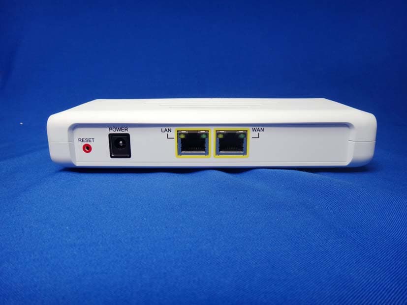
Y38TE1211M
Oct 23, 2013modlet gateway
Equipment Class
PCB - PCS Licensed Transmitter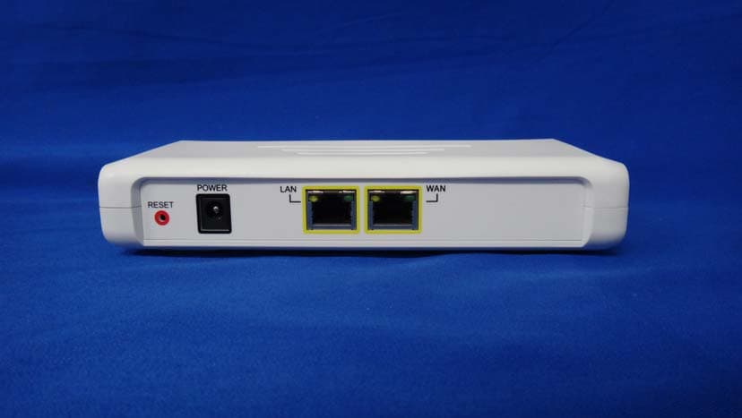
Y38TE1211E
Jun 19, 2013modlet gateway
Equipment Class
DTS - Digital Transmission System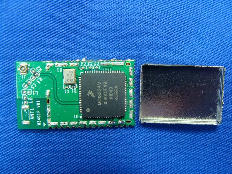
Y38TE7010
Mar 21, 2013modlet IQ
Equipment Class
DTS - Digital Transmission System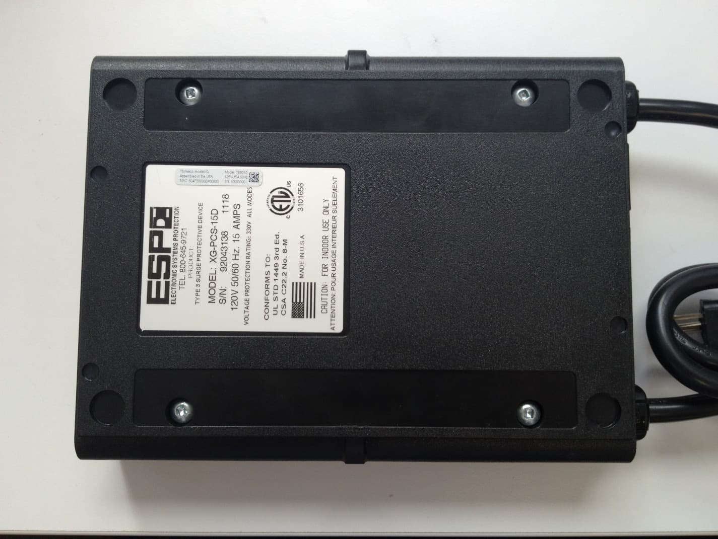
Y38TE6010
Jan 28, 2013TE6010
Equipment Class
DTS - Digital Transmission System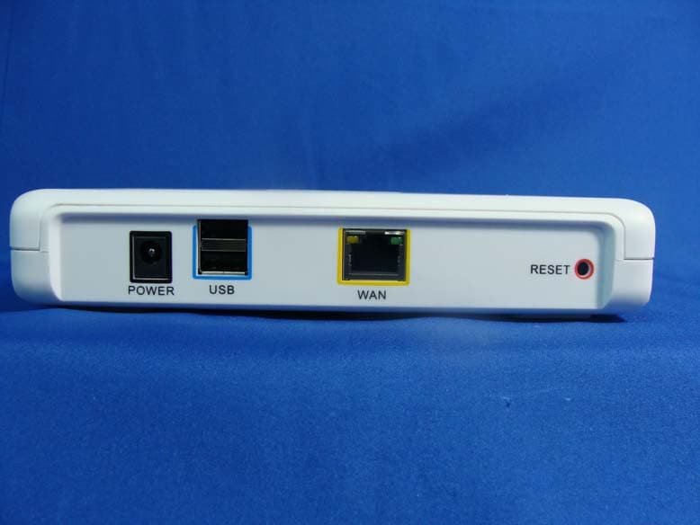
Y38TE1210
Apr 19, 2012modlet gateway
Equipment Class
DTS - Digital Transmission System