YBU282XX0901RC System for rolling shutters / awnings and venetian blinds
elero GmbH Antriebstechnik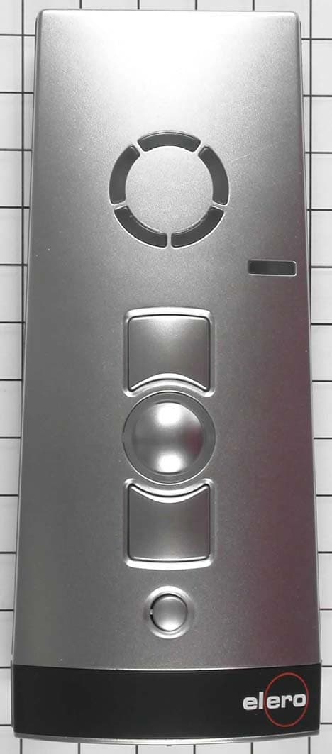
Click to zoom
Application Details
- Equipment Class
- DXX - Part 15 Low Power Communication Device Transmitter
- Date of Grant
- Jun 09, 2010
- Application Purpose
- Original Equipment
- Date of Application
- Jun 09, 2010
- Equipment Note
- RC System for rolling shutters / awnings and venetian blinds
- Frequency Range
- 918.30000000 - 918.30000000
- Company
- elero GmbH Antriebstechnik
- Country
- Germany
Documents & Files
Document Text
Text extracted from the exhibit documents filed with the FCC. Open a document above to read the original.
Users Manual
VarioTel 2-915 No. 282450901, 282460901, 282470901 181221301/0510 EN/FR/ES/PT elero Operating instructions Please take care of the operating instructions! Instructions d’utilisation Veuillez conserver les présentes instructions d’utilisation ! Instrucciones de servicio ¡Por favor, conserve estas instrucciones de servicio Instruções de serviço Por favor conserve as instruções de serviço ! EN FR ES PT elero GmbH Antriebstechnik Linsenhofer Str. 59–63 D-72660 Beuren Tel.: +49 (0) 7025-13-01 Fax: +49 (0) 7025-13-212 www.elero.com [email protected] Device explanation EN-2 EN Device explanation..................................... EN-2 Safety instructions/exclusion of liability.............. EN-3 Scope of supply/ intended use........................ EN-5 Bidirectional radio system/unidirectional radio systemEN- 6 Mounting of the wall bracket.......................... EN-8 Explanation of functions............................... EN-9 Status LED.......................................... EN-9 Group control unit................................... EN-9 Select button........................................ EN-10 Programming the transmitter.......................... EN-11 Programming the transmitter/channel............... EN-11 Programming further transmitters.................... EN-12 Approach limit positions of roller shutter/awning/ venetian blind.......................................... EN-13 Intermediate positions for roller shutters/awnings/ venetian blinds......................................... EN-14 Program intermediate position....................... EN-14 Program ventilation/tilting position................... EN-15 Approach intermediate position...................... EN-15 Approach ventilation/tilting position.................. EN-15 Position deletion..................................... EN-16 Delete ventilation/tilting position..................... EN-16 Deletion of transmitter................................. EN-17 Deletion of individual transmitters................... EN-17 Deletion of all transmitters........................... EN-17 Technical data.......................................... EN-17 Battery replacement.................................... EN-18 Cleaning................................................ EN-18 Disposal................................................ EN-18 Notes on troubleshooting.............................. EN-19 Notes on repair......................................... EN-19 EC-Declaration of conformity.......................... EN-20 Contents EN-1 elero Fixing area for wall bracket Programming button P UP button STOP button Status LED Channel viewing window LED window (automatic/manual mode) DOWN button Select button Battery compartment Back of equipment on front of device Safety instructions EN-4 EN Safety instructions/exclusion of liability EN-3 STOP! Observance of the operating instructions is the prerequisite for disturbance-free operation and fulfilment of any claims related to defects. • Therefore, first read the operating instructions before you use the device! • Ensure that the operating instructions are available to the user in legible form. • The operator must ensure that the basic safety measures are observed and fulfilled. • The operator must have completely read and understood the operating instructions. • The following safety and installation instructions solely refer to the transmitter and not the accessories and drive. Exclusion of liability: It is essential to observe these operating instructions for use if the VarioTel 2 hand-held transmitter is to be used safely and if the various product characteristics and performance features are to be achieved. elero GmbH assumes no liability for personal injuries, property damages and financial losses that arise from non-observance of the operating instructions. Liability for material defects is excluded in such cases. CAUTION! Observe the following safety instructions. Failure to observe them can lead to bodily injuries! General • Never install or commission devices which are damaged. • Only use unmodified original eleroelectrical parts. • If the device is opened without permission or used in an improper manner, or if it is incorrectly installed or operated, there is a risk of damage to persons and property. • The device contains small parts which can be swallowed. Transport • If the transmitter arrives in a damaged condition despite proper packaging, then it must not be commissioned. Immediately report the damage to the transport company. Installation • Note any country-specific conditions when installing the device. • The device may only be used by persons who have read and understood the operating instructions. Operation • Use only in dry rooms. • If one or more transmitters are used for controlling the system, its operating range must stay visible during operation. • Keep children away from the control units. • Replace battery only with identical type (LR06;AA). • Dispose of used batteries properly (collection point). EN-6 EN Scope of supply/Intended use EN-5 Manufacturing note All the ProLine 2 transmitters are subject to 100% testing by elero GmbH before delivery. The ProLine 2 transmitters are made as per the following guidelines: • EN 300 220 (electromagnetic compatibility of radio systems) • ETS 300 683 (Specific conditions for short range radio devices) • CE mark Scope of supply VarioTel 2 (batteries (2 x LR 06; AA) supplied with device) Wall bracket 2 dowels 2 screws Intended use The VarioTel 2 is a multi-channel transmitter. Each channel can be used unidirectionally (compatible with the existing ProLine programme) or bidirectionally. The hand-held transmitter may only be used for controlling roller shutters, venetian blinds and sun protection systems that are fitted with elero radio receivers. Other use, or use which goes beyond this use is not considered to be use for intended purpose. elero GmbH shall not be liable for: • Other uses than those described above • Changes to the device • Imp…
Text truncated - open the document above for the full version.
Cover Letter(s)
YBU282XX0901
Cover Letter(s)
elero GmbH . Antriebstechnik elero GmbH Linsenhofer Str. 59-63 Geschäftsführer Bankverbindungen D-72660 Beuren Rainer Kunz Dresdner Bank Köln (BLZ 370 800 40) 0987008800 Telefon (07025) 13-01 Dipl. Ing. Wolfgang Günther BIC/SWIFT: DRESDEFF370 IBAN: DE9737080040 0987008800 Telefax (07025) 13-212 Amtsgericht Stuttgart HRB 222367 BW Bank Stuttgart (BLZ 600 501 01) 8 680 611 www.elero.com USt.-ID Nr.: DE 812 063 218 Kreissparkasse Esslingen (BLZ 611 500 20) 48 444 446 [email protected] Steuer-Nr. 02/204/0653/0 Postbank Stuttgart (BLZ 600 100 70) 107 181-701 Federal Communications Commission 7435 Oakland Mills Road Columbia, MD 21046 Dr.Prager Phone +497025 13476 Fax +497025 13215 PRR 15.04.2010 Statement of equality of structure Proline2 We the undersigned hereby declare that the Proline2 remote controls in accordance to the Schematics, Parts List, Operating Description, Block Diagram 1. Proline 2 transmitters VarioTel2 art.-no. 28.205.0901 LumeroTel2 art.-no. 28.225.0901 MonoTel2 art.-no. 28.245.0901 2. Proline2 receivers Combio-915 RevoLine art.-no. 28.520.0906 Combio-915 JA art.-no. 28.500.0906 have an equality of structure with following differences only: 1. Differences of Proline2 transmitters - firmware versions of the microcontrollers - different component placement of the PCB in accordance to the schematics/Part lists 2. Differences of Proline2 receivers - firmware versions of the microcontrollers - different cable connections in accordance to the part lists This statement is valid until further written notice from Elero GmbH Antriebstechnik . Sincerely yours, elero GmbH Antriebstechnik Dr.Prager - project management-
External Photos
FCC ID: YBU282XX0901 mikes-testingpartners gmbh File No. T34021-00-03KJ, page 5 of 41 Ohmstrasse 2-4 x 94342 STRASSKIRCHEN x GERMANY Tel.:+49(0)9424-94810 x Fax:+49(0)9424-9481240 Rev. No. 1.1, 23.4.2009 3 EQUIPMENT UNDER TEST 3.1 Photo documentation of the EUT – External Photos VarioTel 2 Front view Rear view FCC ID: YBU282XX0901 mikes-testingpartners gmbh File No. T34021-00-03KJ, page 6 of 41 Ohmstrasse 2-4 x 94342 STRASSKIRCHEN x GERMANY Tel.:+49(0)9424-94810 x Fax:+49(0)9424-9481240 Rev. No. 1.1, 23.4.2009 VarioTel 2 Bottom view VarioTel 2 Top view FCC ID: YBU282XX0901 mikes-testingpartners gmbh File No. T34021-00-03KJ, page 7 of 41 Ohmstrasse 2-4 x 94342 STRASSKIRCHEN x GERMANY Tel.:+49(0)9424-94810 x Fax:+49(0)9424-9481240 Rev. No. 1.1, 23.4.2009 VarioTel 2 Open battery case VarioTel 2 Label view
ID Label/Location Info
FCC ID: YBU282XX0901 mikes-testingpartners gmbh File No. T34021-00-03KJ, page 5 of 41 Ohmstrasse 2-4 x 94342 STRASSKIRCHEN x GERMANY Tel.:+49(0)9424-94810 x Fax:+49(0)9424-9481240 Rev. No. 1.1, 23.4.2009 3 EQUIPMENT UNDER TEST 3.1 Photo documentation of the EUT – External Photos VarioTel 2 Front view Rear view
Internal Photos
FCC ID: YBU282XX0901 mikes-testingpartners gmbh File No. T34021-00-03KJ, page 8 of 41 Ohmstrasse 2-4 x 94342 STRASSKIRCHEN x GERMANY Tel.:+49(0)9424-94810 x Fax:+49(0)9424-9481240 Rev. No. 1.1, 23.4.2009 3.2 Photo documentation of the EUT – Internal Photos VarioTel 2 Internal view / open case (mainboard and RF board together) FCC ID: YBU282XX0901 mikes-testingpartners gmbh File No. T34021-00-03KJ, page 9 of 41 Ohmstrasse 2-4 x 94342 STRASSKIRCHEN x GERMANY Tel.:+49(0)9424-94810 x Fax:+49(0)9424-9481240 Rev. No. 1.1, 23.4.2009 VarioTel 2 Mainboard - PCB top view FCC ID: YBU282XX0901 mikes-testingpartners gmbh File No. T34021-00-03KJ, page 10 of 41 Ohmstrasse 2-4 x 94342 STRASSKIRCHEN x GERMANY Tel.:+49(0)9424-94810 x Fax:+49(0)9424-9481240 Rev. No. 1.1, 23.4.2009 VarioTel 2 Mainboard - PCB rear view FCC ID: YBU282XX0901 mikes-testingpartners gmbh File No. T34021-00-03KJ, page 11 of 41 Ohmstrasse 2-4 x 94342 STRASSKIRCHEN x GERMANY Tel.:+49(0)9424-94810 x Fax:+49(0)9424-9481240 Rev. No. 1.1, 23.4.2009 VarioTel 2 RF board - PCB top view FCC ID: YBU282XX0901 mikes-testingpartners gmbh File No. T34021-00-03KJ, page 12 of 41 Ohmstrasse 2-4 x 94342 STRASSKIRCHEN x GERMANY Tel.:+49(0)9424-94810 x Fax:+49(0)9424-9481240 Rev. No. 1.1, 23.4.2009 VarioTel 2 RF board - PCB rear view
Test Report
FCC ID: YBU282XX0901 mikes-testingpartners gmbh File No. T34021-00-03KJ, page 1 of 44 Ohmstrasse 2-4 x 94342 STRASSKIRCHEN x GERMANY Tel.:+49(0)9424-94810 x Fax:+49(0)9424-9481240 Rev. No. 1.1, 23.4.2009 EMI -- T E S T R E P O R T - FCC Part 15.249 - Test Report No. : T34021-00-03KJ 18. May 2010 ______________________________________________________________________________________________ Date of issue Type / Model Name : VarioTel 2 Product Description : Multi-channel transmitter for controlling roller shutters, veneation blinds and sun protection systems Applicant : elero GmbH Antriebstechnik Address : Linsenhofer Str. 59-63 72660 BEUREN, GERMANY Manufacturer : elero GmbH Antriebstechnik Address : Linsenhofer Str. 59-63 72660 BEUREN, GERMANY Licence holder : elero GmbH Antriebstechnik Address : Linsenhofer Str. 59-63 72660 BEUREN, GERMANY Test Result according to the standards listed in clause 1 test standards: POSITIVE The test report merely corresponds to the test sample. It is not permitted to copy extracts of these test results without the written permission of the test laboratory. DAT-P-207/05-00 Registration No. DAT-P-207/05 FCC ID: YBU282XX0901 mikes-testingpartners gmbh File No. T34021-00-03KJ, page 2 of 44 Ohmstrasse 2-4 x 94342 STRASSKIRCHEN x GERMANY Tel.:+49(0)9424-94810 x Fax:+49(0)9424-9481240 Rev. No. 1.1, 23.4.2009 Contents 1 TEST STANDARDS 3 2 SUMMARY 4 3 EQUIPMENT UNDER TEST 5 3.1 Photo documentation of the EUT – External Photos 5 3.2 Photo documentation of the EUT – Internal Photos 8 3.3 Power supply system utilised 13 3.4 Short description of the equipment under test (EUT) 13 4 TEST ENVIRONMENT 14 4.1 Address of the test laboratory 14 4.2 Environmental conditions 14 4.3 Statement of the measurement uncertainty 14 4.4 Measurement protocol for FCC, VCCI and AUSTEL 14 4.5 Discovery of worst case measurement conditions 16 5 TEST CONDITIONS AND RESULTS 17 5.1 Conducted emissions 17 5.2 Radiated emission of the fundamental wave 18 5.3 Spurious emissions radiated 20 5.4 Emission Bandwidth 24 5.5 Band edge test 28 5.6 Correction for pulse operation (duty cycle) 34 5.7 Antenna application 40 5.8 Receiver radiated emissions 41 6 USED TEST EQUIPMENT AND ACCESSORIES 44 FCC ID: YBU282XX0901 mikes-testingpartners gmbh File No. T34021-00-03KJ, page 3 of 44 Ohmstrasse 2-4 x 94342 STRASSKIRCHEN x GERMANY Tel.:+49(0)9424-94810 x Fax:+49(0)9424-9481240 Rev. No. 1.1, 23.4.2009 1 TEST STANDARDS The tests were performed according to following standards: FCC Rules and Regulations Part 15, Subpart A - General (October, 2009) Part 15, Subpart A, Section 15.31 Measurement standards Part 15, Subpart A, Section 15.33 Frequency range of radiated measurements Part 15, Subpart A, Section 15.35 Measurement detector functions and bandwidths FCC Rules and Regulations Part 15, Subpart C - Intentional Radiators (October, 2009) Part 15, Subpart C, Section 15.203 Antenna requirement Part 15, Subpart C, Section 15.204 External radio frequency power amplifiers and antenna modifications Part 15, Subpart C, Section 15.205 Restricted bands of operation Part 15, Subpart C, Section 15.209 Radiated emission limits, general requirements Part 15, Subpart C, Section 15.249 Operation within the bands 902 - 928 MHz, 2400 - 2483.5 MHz, 5725 - 5875 MHz, and 24.0 - 24.25 GHz ANSI C63.4: 2003 Methods of Measurement of Radio-Noise Emissions from Low- Voltage Electrical and Electronic Equipment in the Range of 9 kHz to 40 GHz. FCC ID: YBU282XX0901 mikes-testingpartners gmbh File No. T34021-00-03KJ, page 4 of 44 Ohmstrasse 2-4 x 94342 STRASSKIRCHEN x GERMANY Tel.:+49(0)9424-94810 x Fax:+49(0)9424-9481240 Rev. No. 1.1, 23.4.2009 2 SUMMARY GENERAL REMARKS: The EuT is working in transmit mode at 915.3 MHz and 918.3 MHz. The frequency range was scanned from 9 kHz to 10000 MHz. All emissions not reported in this test report were more than 10 dB below the specified limit. FINAL ASSESSMENT: The equipment under test fulfills the EMI requirements cited in clause 1 test standards. Date of receipt of test sample : acc. to storage records Testing commenced on : 02. March 2010 Testing concluded on : 12. April 2010 Checked by: Tested by: Klaus Gegenfurtner Dipl.-Ing.(FH) Manager: Radio Group Josef Knab FCC ID: YBU282XX0901 mikes-testingpartners gmbh File No. T34021-00-03KJ, page 5 of 44 Ohmstrasse 2-4 x 94342 STRASSKIRCHEN x GERMANY Tel.:+49(0)9424-94810 x Fax:+49(0)9424-9481240 Rev. No. 1.1, 23.4.2009 3 EQUIPMENT UNDER TEST 3.1 Photo documentation of the EUT – External Photos VarioTel 2 Front view Rear view FCC ID: YBU282XX0901 mikes-testingpartners gmbh File No. T34021-00-03KJ, page 6 of 44 Ohmstrasse 2-4 x 94342 STRASSKIRCHEN x GERMANY Tel.:+49(0)9424-94810 x Fax:+49(0)9424-9481240 Rev. No. 1.1, 23.4.2009 VarioTel 2 Bottom view VarioTel 2 Top view FCC ID: YBU282XX0901 mikes-testingpartners gmbh File No. T34021-00-03KJ, page 7 of 44 Ohmstrasse 2-4 x 94342 STRASSKIRCHEN x GERMANY Tel.:+49(0)9424-94810 x Fax:+49(0)9424-9481240 Rev. No. 1.1, 23.4.2009 VarioTel 2 Open battery case VarioTel 2 Label view FCC ID: YBU282XX0901 mikes-testingpartners gmbh File No. T34021-00-03KJ, page 8 of 44 Ohmstrasse 2-4 x 94342 STRASSKIRCHEN x GERMANY Tel.:+49(0)9424-94810 x Fax:+49(0)9424-9481240 Rev. No. 1.1, 23.4.2009 3.2 Photo documentation of the EUT – Internal Photos VarioTel 2 Internal view / open case (mainboard and RF board together) FCC ID: YBU282XX0901 mikes-testingpartners gmbh File No. T34021-00-03KJ, page 9 of 44 Ohmstrasse 2-4 x 94342 STRASSKIRCHEN x GERMANY Tel.:+49(0)9424-94810 x Fax:+49(0)9424-9481240 Rev. No. 1.1, 23.4.2009 VarioTel 2 Mainboard - PCB top view FCC ID: YBU282XX0901 mikes-testingpartners gmbh File No. T34021-00-03KJ, page 10 of 44 Ohmstrasse 2-4 x 94342 STRASSKIRCHEN x GERMANY Tel.:+49(0)9424-94810 x Fax:+49(0)9424-9481240 Rev. No. 1.1, 23.4.2009 VarioTel 2 Mainboard - PCB rear view FCC ID: YBU282XX0901 mikes-testingpartners gmbh File No. T34021-00-03KJ, page 11 of 44 Ohmstrasse 2-4 x 94342 STRASSKIRCHEN x GERMANY Tel.:+49(0)…
Text truncated - open the document above for the full version.
Test Setup Photos
FCC ID: YBU282XX0901 mikes-testingpartners gmbh File No. T34021-00-03KJ, page 18 of 41 Ohmstrasse 2-4 x 94342 STRASSKIRCHEN x GERMANY Tel.:+49(0)9424-94810 x Fax:+49(0)9424-9481240 Rev. No. 1.1, 23.4.2009 5.2 Radiated emission of the fundamental wave For test instruments and accessories used see section 6 Part CPR 2. 5.2.1 Description of the test location Test location: OATS1 Test distance: 3 metres 5.2.2 Photo documentation of the test set-up FCC ID: YBU282XX0901 mikes-testingpartners gmbh File No. T34021-00-03KJ, page 19 of 41 Ohmstrasse 2-4 x 94342 STRASSKIRCHEN x GERMANY Tel.:+49(0)9424-94810 x Fax:+49(0)9424-9481240 Rev. No. 1.1, 23.4.2009 5.2.1 Applicable standard According to FCC Part 15C, Section 15.249(a): The field strength of emissions from intentional radiators operated within these frequency bands shall comply with the effective limits. 5.2.2 Description of Measurement The radiated emission of the fundamental wave from the EUT is measured using a tuned receiver and appropriate linear polarized antennas. Receiver settings: RBW: 120 kHz Detector: Quasi peak 5.2.3 Test result Channel 1 Frequency (MHz) Level QP (dBμV) Correct. factor (dB) Corrected level dB(μV/m) Limit dB(μV/m) Delta (dB) 915.30 62.8 28.5 91.6 94.0 2.4 Channel 2 Frequency (MHz) Level QP (dBμV) Correct. factor (dB) Corrected level dB(μV/m) Limit dB(μV/m) Delta (dB) 918.30 63.9 28.8 92.7 94.0 1.3 Limit according to FCC Section 15.249(a) for fundamental Frequency Field strength of fundamental (MHz) (mV/m) dB(μV/m) 902 - 928 50 94 The requirements are FULFILLED. Remarks: FCC ID: YBU282XX0901 mikes-testingpartners gmbh File No. T34021-00-03KJ, page 20 of 41 Ohmstrasse 2-4 x 94342 STRASSKIRCHEN x GERMANY Tel.:+49(0)9424-94810 x Fax:+49(0)9424-9481240 Rev. No. 1.1, 23.4.2009 5.3 Spurious emissions radiated For test instruments and accessories used see section 6 Part SER 1, SER 2, SER 3. 5.3.1 Description of the test location Test location: OATS1 Test location: Anechoic Chamber A2 Test distance: 3 metres 5.3.2 Photo documentation of the test set-up FCC ID: YBU282XX0901 mikes-testingpartners gmbh File No. T34021-00-03KJ, page 21 of 41 Ohmstrasse 2-4 x 94342 STRASSKIRCHEN x GERMANY Tel.:+49(0)9424-94810 x Fax:+49(0)9424-9481240 Rev. No. 1.1, 23.4.2009
Contact Information
Applicant
Matthias Henschel(Dr.)
Test Firm
CSA Group Bayern GmbHThomas Weise
Technical Specifications
| # | Rule Parts | Frequency Range | Power Output |
|---|---|---|---|
| 2 | 15C | 918.3 MHz - 918.3 MHz | - |
Other Applications from elero GmbH Antriebstechnik
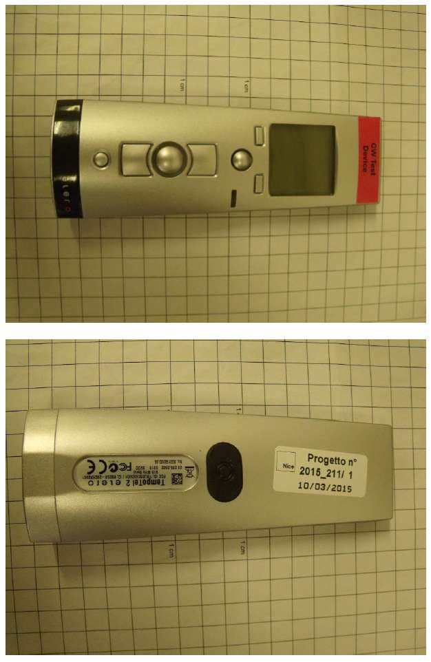
YBU2826X09X
Jan 25, 2016Low power transceiver for screen market
Equipment Class
DSR - Part 15 Remote Control/Security Device Transceiver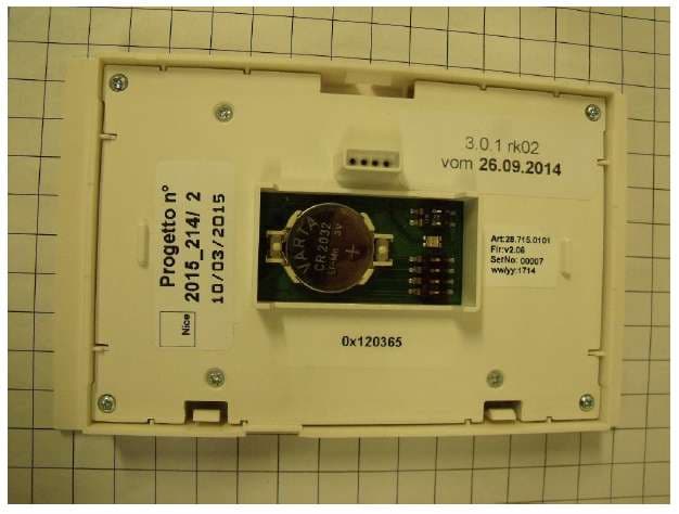
YBU2871X09X
Oct 22, 2015Low power transceiver for screen market
Equipment Class
DXT - Part 15 Low Power Transceiver, Rx Verified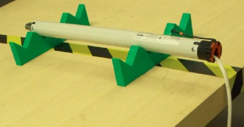
YBURT915S
Sep 29, 2013Tubular motors with electronic limit switch with transceiver at 915MHz
Equipment Class
DXT - Part 15 Low Power Transceiver, Rx Verified
YBURT915
Aug 08, 2013Tubular Motor with Electronic Limit Switch
Equipment Class
DXT - Part 15 Low Power Transceiver, Rx Verified
YBU285XX0901
Jun 08, 2010RC System for rolling shutters / awnings and venetian blinds
Equipment Class
DXX - Part 15 Low Power Communication Device Transmitter