YBURT915Tubular Motor with Electronic Limit Switch
elero GmbH Antriebstechnik
Click to zoom
Application Details
- Equipment Class
- DXT - Part 15 Low Power Transceiver, Rx Verified
- Date of Grant
- Aug 08, 2013
- Application Purpose
- Original Equipment
- Date of Application
- Aug 08, 2013
- Equipment Note
- Tubular Motor with Electronic Limit Switch
- Frequency Range
- 918.30000000 - 918.30000000
- Company
- elero GmbH Antriebstechnik
- Country
- Germany
Documents & Files
Document Text
Text extracted from the exhibit documents filed with the FCC. Open a document above to read the original.
Users Manual
Roller shutter drive RolTop 120 V / 60 Hz 138186501_US+CA_0513 Roller shutter drive RolTop 120 V / 60 Hz 1 Operating and installation instructions Please keep these operating instructions for later use and have them available during the complete service life of the product! The German version of these operating instructions is the original version. All foreign language documents are translations of the original version. All rights reserved with regard to patent claim or submission of design or utility patent. 2 General information The structure of these operating instructions is based on the service life phases of the electrical drive (subsequently referred to as product). The manufacturer reserves the right to make changes to the technical data included in these operating instructions. The- se may deviate from the respective model of the product while the factual information are generally not changed and are not losing their validity. The current state-of-the-art can be obtained from the manufacturer at all times. Potential claims cannot be asserted. Deviations from text and pictori- al statements are not possible and depending on the tech- nical development, setup and accessories of the product. Deviating information on special models are included by the manufacturer in the sales documentation. Other information shall remain unaffected by this. 2.1 Standards and guidelines During system design, basic safety and health requirements of applicable laws, standards and guidelines were obser- ved. The safety is confi rmed by means of the Declaration of Conformity (refer to „EC Declaration of Conformity“). All safety information in these operating instructions are based on currently applicable laws and regulations in Germany. All information in the operating instructions must be obser- Table of contents 1 Operating and installation instructions 1 2 General information 1 2.1 Standards and guidelines 1 2.2 Intended use 2 2.3 Foreseeable misuse 2 2.4 Warranty and liability 2 2.5 Customer service of the manufacturer 2 3 Safety 2 3.1 General safety instructions 2 3.2 Layout of safety instructions 2 3.3 General safety principles 3 3.4 General obligations of the operator 3 3.5 General requirements on personnel 3 3.6 Safety instructions on technical condition 3 3.7 Safety instructions on transport, assembly and installation 4 3.8 Safety instructions on operation 4 3.9 Safety instructions on electrical installation 4 4 Product description 4 5 Installation 4 5.1 Mechanical mounting 5 5.2 Electrical connection 5 5.3 Connection example, RolTop 120 V / 60 Hz 6 5.4 Parallel connection 6 5.5 Commissioning 6 5.6 End position and relief settings 6 5.6.1 Relief function for end position(s) 6 5.6.2 Relief function at the upper stop 6 5.6.3 Relief function at the lower stop 6 5.6.4 Changing / deleting of end positions and deleting the relief function 6 5.6.5 Four options for end position settings 6 5.6.6 Option A: Upper and lower end position freely confi gurable 7 5.6.7 Option B: Fixed upper end position, lower end position freely confi gurable 7 5.6.8 Option C: Fixed upper and lower end position 7 5.6.9 Option D: Upper end position freely confi gurable, fi xed lower end position 8 5.7 Technical data 8 6 Troubleshooting 8 7 Servicing 8 8 Cleaning 8 9 Repair 8 10 Address 8 11 Disassembly and disposal 8 12 EC Declaration of Conformity 9 13 EN: Addendum to the manual UL approval 9 14 FR: Addendum au manuel Homologation UL 9 3 Safety 3.1 General safety instructions These operation and installation instructions include all safety instructions for prevention and avoiding of dangers during handling of the product over its entire life cycles. Compliance with all specifi ed safety instructions ensures safe operation of the product. 3.2 Layout of safety instructions The safety instructions in this document are marked by dan- ger signs and safety symbols and are designed according to the SAFE principle. They include information on type and source of the danger as well as on possible consequences and on prevention of the danger. The following table defi nes the design and description of the levels of danger with potential physical injuries as they are used in these operating instructions. Symbol Signal word Description DANGERWarns of a potential ac- cident with if instructions are not complied with leading to life-threatening, irreversible injuries or death. WARNINGWarns of a potential ac- cident with if instructions are not complied with lea- ding to severe, potentially life-threatening, irreversib- le injuries or death. CAUTIONWarns of a potential ac- cident with if instructions are not complied with leading to light, reversible injuries. Fig. 1 Notation of personal injury The following table describes symbols used in these ope- rating instructions for illustration of dangerous situations in connection with the respective symbol for the level of danger. Symbol Description Danger due to voltage, electrical shock: This symbol indicates dangers due to electricity. Fig. 2 Notation of a specifi c danger The following table defi nes the illustration and description of situations in these operating instructions that may lead to damage to the product or indicates facts, conditions, tips and information. 2 | US+CA © elero GmbH Intended use | Safety ved at all times. Apart from the safety instructions in these operating instructions, applicable local regulations on pre- vention of accidents, environmental protection and occupa- tional safety must be observed. Regulations and standards for safety assessment can be found in the EC Declaration of Conformity. 2.2 Intended use This product is intended for use in facade construction for driving electrical sun protection devices. Decisive for the determination of the drive system is the elero drive computation program (http://elero.com/ en;service;drive-computation-program.htm). Other applications must be approved in advance by the ma- nufacturer elero GmbH Antriebstechnik (refer to „Add…
Text truncated - open the document above for the full version.
Users Manual
Roller shutter drive RolTop-915 120 V / 60 Hz 138186606_US+CA_0513 Roller shutter drive RolTop-915 120V / 60Hz 1 Operating and installation instructions Please keep these operating instructions for later use and have them available during the complete service life of the product! The German version of these operating instructions is the original version. All foreign language documents are translations of the original version. All rights reserved with regard to patent claim or submission of design or utility patent. 2 General information The structure of these operating instructions is based on the service life phases of the electrical drive (subsequently referred to as product). The manufacturer reserves the right to make changes to the technical data included in these operating instructions. The- se may deviate from the respective model of the product while the factual information are generally not changed and are not losing their validity. The current state-of-the-art can be obtained from the manufacturer at all times. Potential claims cannot be asserted. Deviations from text and pictori- al statements are not possible and depending on the tech- nical development, setup and accessories of the product. Deviating information on special models are included by the manufacturer in the sales documentation. Other information shall remain unaffected by this. Table of contents 1 Operating and installation instructions 1 2 General information 1 2.1 Standards and guidelines 2 2.2 Intended use 2 2.3 Foreseeable misuse 2 2.4 Warranty and liability 2 2.5 Customer service of the manufacturer 2 3 Safety 2 3.1 General safety instructions 2 3.2 Layout of safety instructions 2 3.3 General safety principles 3 3.4 General obligations of the operator 3 3.5 General requirements on personnel 3 3.6 Safety instructions on technical condition 4 3.7 Safety instructions on transport, assembly and installation 4 3.8 Safety instructions on operation 4 3.9 Safety instructions on electrical installation 4 4 Product description 4 5 Installation 5 5.1 Mechanical mounting 5 5.2 Electrical connection 6 5.3 Connection example, RolTop-915 120 V / 60 Hz 6 5.4 Parallel connection 6 5.5 Commissioning 6 5.5.1 Installation cable connection 6 5.5.2 Wireless connection (transmitter operation) 7 5.6 End position and relief settings 7 5.6.1 Relief function for end position(s) 7 5.6.2 Relief function at the upper stop 7 5.6.3 Relief function at the lower stop 7 5.6.4 Changing / deleting of end positions and deleting the relief function 7 5.6.5 Programming or deleting additional fabric positions 7 5.6.6 Four options for end position settings 7 5.6.7 Option A: Upper and lower end position freely confi gurable 8 5.6.8 Option B: Fixed upper end position, lower end position freely confi gurable 8 5.6.9 Option C: Fixed upper and lower end position 8 5.6.10 Option D: Upper end position freely confi gurable, fi xed lower end position 8 5.7 Transmitter programming 9 5.8 Programming additional transmitters(s) 9 5.9 Technical data 9 6 Troubleshooting 9 7 Servicing 9 8 Cleaning 9 9 Repair 10 10 Address 10 11 Disposal / scrapping 10 12 EC Declaration of Conformity 10 13 US: Addendum to the manual UL approval 10 14 CA: Addendum au manuel Homologation UL 10 • Incorrect installation, commissioning or operation of the product • Structural changes to the product without the written approval of the manufacturer • Operating the product with incorrectly installed connec- tions, defective safety equipment or with not properly installed safety and protective equipment • Failure to observe the safety regulations and instructions included in these operating instructions • Non-compliance with the specifi ed technical data 2.5 Customer service of the manufacturer In case of a defect, the product may only be repaired by the manufacturer. Please refer to section „Address“ for the return address of the customer service. If you did not acquire the product directly from elero, please contact your supplier. 3 Safety 3.1 General safety instructions These operation and installation instructions include all safety instructions for prevention and avoiding of dangers during handling of the product over its entire life cycles. Compliance with all specifi ed safety instructions ensures safe operation of the product. 3.2 Layout of safety instructions The safety instructions in this document are marked by dan- ger signs and safety symbols and are designed according to the SAFE principle. They include information on type and source of the danger as well as on possible consequences and on prevention of the danger. The following table defi nes the design and description of the levels of danger with potential physical injuries as they are used in these operating instructions. Symbol Signal word Description DANGERWarns of a potential ac- cident with if instructions are not complied with leading to life-threatening, irreversible injuries or death. WARNINGWarns of a potential ac- cident with if instructions are not complied with lea- ding to severe, potentially life-threatening, irreversib- le injuries or death. CAUTIONWarns of a potential ac- cident with if instructions are not complied with leading to light, reversible injuries. Fig. 1 Notation of personal injury The following table describes symbols used in these ope- rating instructions for illustration of dangerous situations in connection with the respective symbol for the level of danger. 2 | US+CA © elero GmbH Standards and guidelines | Safety 2.1 Standards and guidelines During system design, basic safety and health requirements of applicable laws, standards and guidelines were obser- ved. The safety is confi rmed by means of the Declaration of Conformity (refer to „EC Declaration of Conformity“). All safety information in these operating instructions are based on currently applicable laws and regulations in Germany. All information in the operating instructions must be obser- ved at all times. Apart from the safety instru…
Text truncated - open the document above for the full version.
Users Manual
Roller shutter drive SunTop 120V / 60 Hz 138186701_US+CA_0513 Roller shutter drive SunTop 120 V / 60 Hz 1 Operating and installation instructions Please keep these operating instructions for later use and have them available during the complete service life of the product! The German version of these operating instructions is the original version. All foreign language documents are translations of the original version. All rights reserved with regard to patent claim or submission of design or utility patent. 2 General information The structure of these operating instructions is based on the service life phases of the electrical drive (subsequently referred to as product). The manufacturer reserves the right to make changes to the technical data included in these operating instructions. The- se may deviate from the respective model of the product while the factual information are generally not changed and are not losing their validity. The current state-of-the-art can be obtained from the manufacturer at all times. Potential claims cannot be asserted. Deviations from text and pictori- al statements are not possible and depending on the tech- nical development, setup and accessories of the product. Deviating information on special models are included by the manufacturer in the sales documentation. Other information shall remain unaffected by this. 2.1 Standards and guidelines During system design, basic safety and health requirements of applicable laws, standards and guidelines were obser- ved. The safety is confi rmed by means of the Declaration of Conformity (refer to „EC Declaration of Conformity“). All safety information in these operating instructions are based on currently applicable laws and regulations in Germany. All information in the operating instructions must be obser- Table of contents 1 Operating and installation instructions 1 2 General information 1 2.1 Standards and guidelines 1 2.2 Intended use 2 2.3 Foreseeable misuse 2 2.4 Warranty and liability 2 2.5 Customer service of the manufacturer 2 3 Safety 2 3.1 General safety instructions 2 3.2 Layout of safety instructions 2 3.3 General safety principles 3 3.4 General obligations of the operator 3 3.5 General requirements on personnel 3 3.6 Safety instructions on technical condition 3 3.7 Safety instructions on transport, assembly and installation 4 3.8 Safety instructions on operation 4 3.9 Safety instructions on electrical installation 4 4 Product description 4 5 Installation 4 5.1 Mechanical mounting 5 5.2 Electrical connection 5 5.3 Connection example, SunTop 120 V / 60 Hz 6 5.4 Parallel connection 6 5.5 Commissioning 6 5.6 End position and relief settings 6 5.6.1 Relief function for end position(s) 6 5.6.2 Relief function at the upper stop 6 5.6.3 Relief function at the lower stop 6 5.6.4 Changing / deleting of end positions and deleting the relief function 6 5.6.5 Four options for end position settings 7 5.6.6 Option A: Upper and lower end position freely confi gurable 7 5.6.7 Option B: Fixed upper end position, lower end position freely confi gurable 7 5.6.8 Option C: Fixed upper and lower end position 7 5.6.9 Option D: Upper end position freely confi gurable, fi xed lower end position 8 5.7 Technical data 8 6 Troubleshooting 8 7 Servicing 8 8 Cleaning 8 9 Repair 8 10 Address 8 11 Disposal / scrapping 8 12 EC Declaration of Conformity 9 13 US: Addendum to the manual UL approval 9 14 CA: Addendum au manuel Homologation UL 9 3 Safety 3.1 General safety instructions These operation and installation instructions include all safety instructions for prevention and avoiding of dangers during handling of the product over its entire life cycles. Compliance with all specifi ed safety instructions ensures safe operation of the product. 3.2 Layout of safety instructions The safety instructions in this document are marked by dan- ger signs and safety symbols and are designed according to the SAFE principle. They include information on type and source of the danger as well as on possible consequences and on prevention of the danger. The following table defi nes the design and description of the levels of danger with potential physical injuries as they are used in these operating instructions. Symbol Signal word Description DANGERWarns of a potential ac- cident with if instructions are not complied with leading to life-threatening, irreversible injuries or death. WARNINGWarns of a potential ac- cident with if instructions are not complied with lea- ding to severe, potentially life-threatening, irreversib- le injuries or death. CAUTIONWarns of a potential ac- cident with if instructions are not complied with leading to light, reversible injuries. Fig. 1 Notation of personal injury The following table describes symbols used in these ope- rating instructions for illustration of dangerous situations in connection with the respective symbol for the level of danger. Symbol Description Danger due to voltage, electrical shock: This symbol indicates dangers due to electricity. Fig. 2 Notation of a specifi c danger The following table defi nes the illustration and description of situations in these operating instructions that may lead to damage to the product or indicates facts, conditions, tips and information. 2 | US+CA © elero GmbH Intended use | Safety ved at all times. Apart from the safety instructions in these operating instructions, applicable local regulations on pre- vention of accidents, environmental protection and occupa- tional safety must be observed. Regulations and standards for safety assessment can be found in the EC Declaration of Conformity. 2.2 Intended use This product is intended for use in facade construction for driving electrical sun protection devices. Decisive for the determination of the drive system is the elero drive computation program (http://elero.com/ en;service;drive-computation-program.htm). Other applications must be approved in advance by the ma- nufacturer elero GmbH Antriebstechnik (refer to „Address“…
Text truncated - open the document above for the full version.
Users Manual
Roller shutter drive SunTop-915 120 V / 60 Hz 138186806_US+CA_0513 Roller shutter drive SunTop-915 120V / 60Hz 1 Operating and installation instructions Please keep these operating instructions for later use and have them available during the complete service life of the product! The German version of these operating instructions is the original version. All foreign language documents are translations of the original version. All rights reserved with regard to patent claim or submission of design or utility patent. 2 General information The structure of these operating instructions is based on the service life phases of the electrical drive (subsequently referred to as product). The manufacturer reserves the right to make changes to the technical data included in these operating instructions. The- se may deviate from the respective model of the product while the factual information are generally not changed and are not losing their validity. The current state-of-the-art can be obtained from the manufacturer at all times. Potential claims cannot be asserted. Deviations from text and pictori- al statements are not possible and depending on the tech- nical development, setup and accessories of the product. Deviating information on special models are included by the manufacturer in the sales documentation. Other information shall remain unaffected by this. Table of contents 1 Operating and installation instructions 1 2 General information 1 2.1 Standards and guidelines 2 2.2 Intended use 2 2.3 Foreseeable misuse 2 2.4 Warranty and liability 2 2.5 Customer service of the manufacturer 2 3 Safety 2 3.1 General safety instructions 2 3.2 Layout of safety instructions 2 3.3 General safety principles 3 3.4 General obligations of the operator 3 3.5 General requirements on personnel 3 3.6 Safety instructions on technical condition 4 3.7 Safety instructions on transport, assembly and installation 4 3.8 Safety instructions on operation 4 3.9 Safety instructions on electrical installation 4 4 Product description 4 5 Installation 5 5.1 Mechanical mounting 5 5.2 Electrical connection 6 5.3 Connection example SunTop-915 120 V / 60 Hz 6 5.4 Parallel connection 6 5.5 Commissioning 6 5.5.1 Installation cable connection 6 5.5.2 Wireless connection (transmitter operation) 6 5.6 End position and relief settings 6 5.6.1 Relief function for end position(s) 7 5.6.2 Relief function at the upper stop 7 5.6.3 Relief function at the lower stop 7 5.6.4 Changing / deleting of end positions and deleting the relief function 7 5.6.5 Programming or deleting additional fabric positions 7 5.6.6 Four options for end position settings 7 5.6.7 Option A: Upper and lower end position freely confi gurable 7 5.6.8 Option B: Fixed upper end position, lower end position freely confi gurable 8 5.6.9 Option C: Fixed upper and lower end position 8 5.6.10 Option D: Upper end position freely confi gurable, fi xed lower end position 8 5.7 Transmitter programming 8 5.8 Programming additional transmitters(s) 9 5.9 Technical data 9 6 Troubleshooting 9 7 Servicing 9 8 Cleaning 9 9 Repair 9 10 Address 9 11 Disposal / scrapping 10 12 EC Declaration of Conformity 10 13 US: Addendum to the manual UL approval 10 14 CA: Addendum au manuel Homologation UL 10 • Improper use of the product • Incorrect installation, commissioning or operation of the product • Structural changes to the product without the written approval of the manufacturer • Operating the product with incorrectly installed connec- tions, defective safety equipment or with not properly installed safety and protective equipment • Failure to observe the safety regulations and instructions included in these operating instructions • Non-compliance with the specifi ed technical data 2.5 Customer service of the manufacturer In case of a defect, the product may only be repaired by the manufacturer. Please refer to section „Address“ for the return address of the customer service. If you did not acquire the product directly from elero, please contact your supplier. 3 Safety 3.1 General safety instructions These operation and installation instructions include all safety instructions for prevention and avoiding of dangers during handling of the product over its entire life cycles. Compliance with all specifi ed safety instructions ensures safe operation of the product. 3.2 Layout of safety instructions The safety instructions in this document are marked by dan- ger signs and safety symbols and are designed according to the SAFE principle. They include information on type and source of the danger as well as on possible consequences and on prevention of the danger. The following table defi nes the design and description of the levels of danger with potential physical injuries as they are used in these operating instructions. Symbol Signal word Description DANGERWarns of a potential ac- cident with if instructions are not complied with leading to life-threatening, irreversible injuries or death. WARNINGWarns of a potential ac- cident with if instructions are not complied with lea- ding to severe, potentially life-threatening, irreversib- le injuries or death. CAUTIONWarns of a potential ac- cident with if instructions are not complied with leading to light, reversible injuries. Fig. 1 Notation of personal injury The following table describes symbols used in these ope- rating instructions for illustration of dangerous situations in connection with the respective symbol for the level of danger. 2 | US+CA © elero GmbH Standards and guidelines | Safety 2.1 Standards and guidelines During system design, basic safety and health requirements of applicable laws, standards and guidelines were obser- ved. The safety is confi rmed by means of the Declaration of Conformity (refer to „EC Declaration of Conformity“). All safety information in these operating instructions are based on currently applicable laws and regulations in Germany. All information in the operating instructions must be obser- ved at all times. A…
Text truncated - open the document above for the full version.
Test Report
FCC test report Notice: The result of tests and checks reported in this Test Report refer exclusively to the samples tested and described in the Report itself. This report shall not be reproduced partially or in its entirely without written approval of Nice S.p.A. Report nr. 25416FCC1 page 1 / 45 date: 31 July 2013 Nice S.p.A. Oderzo TV Italia tel. +39.0422.853838 www.niceforyou.com Test report nr. 25416FCC12 Measurements performed in accordance with: FCC Rules: code of Federal Regulations (CFR) no. 47 PART 15 – RADIO FREQUENCY DEVICES Product: Tubular motor with transceiver inside Tested model: RolTopMxx/yy-915 SunTopMxx/yy-915 (xx = 2, 4, 7, 10, 16, 30, 36; yy = 108, 70, 28, 17, 12) FCC ID YBURT915 Applicant: elero gmbh Antriebstechnik Linsenhofer Str. 59-63 D-72660 Beuren elero gmbh Antriebstechnik Linsenhofer Str. 59-63 D-72660 Beuren Manufacturer: elero gmbh Antriebstechnik Linsenhofer Str. 59-63 D-72660 Beuren Trademark: elero Testing Laboratory Nice S.p.A. Via Pezza Alta, 13 I-31046 Rustignè di Oderzo (TV) Registration number: 771316 Date of receipt sample: 27 th May 2013 Testing date: 27 th May – 11 th June 2013 Issue date: 8 August 2013 Tested by: L. Pastres Checked by: E. Campion FCC test report Report nr. 25416FCC1 page 2 / 45 date: 31 July 2013 Nice S.p.A. Oderzo TV Italia tel. +39.0422.853838 www.niceforyou.com Contents Contents ............................................................................................................................. 2 1 General Description of Equipment under Test ............................................................. 3 1.1 Applicant .................................................................................................................... 3 1.2 Manufacturer .............................................................................................................. 3 1.3 Equipment classification ............................................................................................. 3 1.4 Basic Description of equipment under test ................................................................. 4 1.5 Feature of equipment under test ................................................................................ 5 2 Test configuration of equipment under test ................................................................. 6 2.1 Environmental conditions ........................................................................................... 6 2.2 Description of support equipment............................................................................... 6 2.3 Interface identification and connection diagram of test system .................................. 7 3 Operation of equipment under test ............................................................................... 8 3.1 Operating test conditions ........................................................................................... 8 4 Tests identification and result ....................................................................................... 9 4.1 Methods of measurement .......................................................................................... 9 4.2 Frequency range investigated .................................................................................... 9 5 Tests .............................................................................................................................. 10 5.1 Antenna requirements .............................................................................................. 10 5.2 Conduced emission .................................................................................................. 11 5.3 Radiated emission .................................................................................................... 14 5.4 Timing of the transmitter .......................................................................................... 20 5.5 Transmit behaviour after releasing the TX-button .................................................... 22 5.6 Radiated output power ............................................................................................. 23 5.8 Compliance with the limit of FCC ............................................................................. 27 5.9 Spurious emission - radiated .................................................................................... 28 5.10 Occuped bandwith ................................................................................................... 29 6 Measurement and Test Equipment instrumentation.................................................. 30 7 Photographic Documentation ...................................................................................... 33 8.1 EUT Identification ..................................................................................................... 33 8.2 Test Set-up .............................................................................................................. 39 Annex 1 ............................................................................................................................. 44 Annex 2 ............................................................................................................................. 45 FCC test report Report nr. 25416FCC1 page 3 / 45 date: 31 July 2013 Nice S.p.A. Oderzo TV Italia tel. +39.0422.853838 www.niceforyou.com 1 General Description of Equipment under Test 1.1 Applicant Name: elero gmbh Antriebstechnik Address: Linsenhofer Str. 65 D-72660 Beuren Country: GERMANY 1.2 Manufacturer Name: elero gmbh Antriebstechnik Address: Linsenhofer Str. 65 D-72660 Beuren Country: GERMANY 1.3 Equipment classification According to definition 15.3 (o) is a intentional Radiator operating within the Bands: so it shall fulfil provisions of 47CFR Part 15 Subpart C – international radiators – and Section 15.209. According to definition 15.3 (z) is a unintentional Radiator: So it shall fulfil provisions of 47CFR Part …
Text truncated - open the document above for the full version.
Contact Information
Applicant
Matthias Henschel(Dr.)
Technical Contact
Non-Technical Contact
elero GmbHReinhard Prager
Test Firm
NICE S.p.A.Enrico Campion
Technical Specifications
| # | Rule Parts | Frequency Range | Power Output |
|---|---|---|---|
| 1 | 15C | 918.3 MHz - 918.3 MHz | - |
Other Applications from elero GmbH Antriebstechnik
YBU2826X09X
Jan 25, 2016Low power transceiver for screen market
Equipment Class
DSR - Part 15 Remote Control/Security Device Transceiver
YBU2871X09X
Oct 22, 2015Low power transceiver for screen market
Equipment Class
DXT - Part 15 Low Power Transceiver, Rx Verified
YBURT915S
Sep 29, 2013Tubular motors with electronic limit switch with transceiver at 915MHz
Equipment Class
DXT - Part 15 Low Power Transceiver, Rx Verified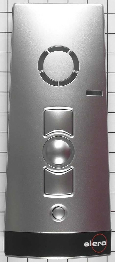
YBU282XX0901
Jun 09, 2010RC System for rolling shutters / awnings and venetian blinds
Equipment Class
DXX - Part 15 Low Power Communication Device Transmitter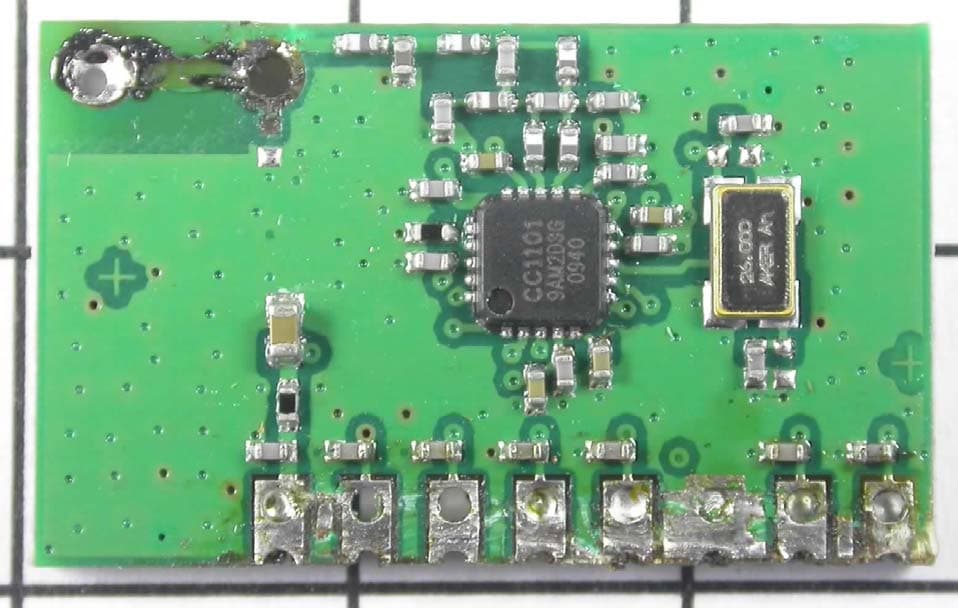
YBU285XX0901
Jun 08, 2010RC System for rolling shutters / awnings and venetian blinds
Equipment Class
DXX - Part 15 Low Power Communication Device Transmitter