YWW-BLNRhose end controller
SOLEM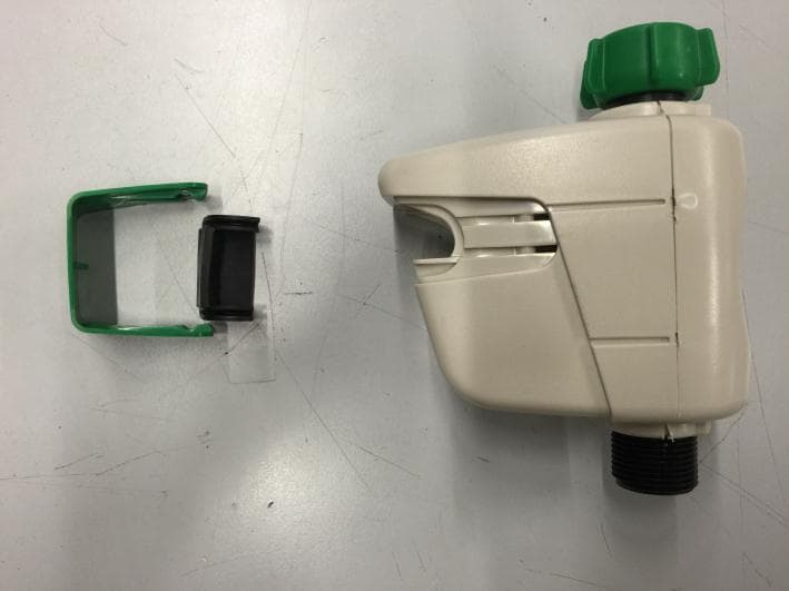
Click to zoom
Application Details
- Equipment Class
- DSS - Part 15 Spread Spectrum Transmitter
- Date of Grant
- Mar 29, 2015
- Application Purpose
- Original Equipment
- Date of Application
- Mar 26, 2015
- Equipment Note
- hose end controller
- Frequency Range
- 2402.00000000 - 2480.00000000
- Company
- SOLEM
- Country
- France
Documents & Files
Document Text
Text extracted from the exhibit documents filed with the FCC. Open a document above to read the original.
Users Manual
Page 1/4 LCIE Laboratoire de Moirans Z.I. Centr’Alp 170, Rue de Chatagnon 38430 MOIRANS-FRANCE USER MANUAL (FCC STATEMENT) FCCID: YWW-BLNR This is a copy of the page where the FCC statement is included: 60NOTI-ADD-ISOLUS[-0114-] Page 2/4 LCIE Laboratoire de Moirans Z.I. Centr’Alp 170, Rue de Chatagnon 38430 MOIRANS-FRANCE Page 3/4 LCIE Laboratoire de Moirans Z.I. Centr’Alp 170, Rue de Chatagnon 38430 MOIRANS-FRANCE Page 4/4 LCIE Laboratoire de Moirans Z.I. Centr’Alp 170, Rue de Chatagnon 38430 MOIRANS-FRANCE
Users Manual
FR - Exposition RF : Cet appareil est conforme à la réglementation FCC concernant les fréquences radio et aux limites fixées par Industry Canada concernant l'exposition du grand public aux fréquences radio. Cet appareil doit être installé à une distance d'au moins 20 cm de la population et ne doit pas être localisé au même endroit ou opérer simultanément avec aucune autre antenne ou transmetteur. DECLARATION FCC Exigences d'étiquetage Cet appareil est conforme au chapitre 15 des règlements de la FCC. L'opération est soumise aux deux conditions suivantes: (1) Cet appareil ne peut causer d'interférences nuisibles, et (2) cet appareil doit accepter toute interférence reçue, y compris les interférences qui peuvent provoquer un fonctionnement indésirable. Information pour l'utilisateur Attention, tout changements ou modifications non expressément approuvés par la partie responsable de la conformité pourraient annuler l'autorité de l'utilisateur de faire fonctionner l'équipement. NOTE : Cet équipement a été testé et approuvé conforme aux limites pour un appareil numérique de classe B, conformément à la partie 15 des règlements de la FCC. Ces limites sont conçues pour fournir une protection raisonnable contre les interférences nuisibles dans une installation résidentielle. Cet équipement génère, utilise et peut émettre des fréquences radio et, s'il n'est pas installé et utilisé conformément aux instructions, peut provoquer des interférences nuisibles aux communications radio. Cependant, il n'existe aucune garantie queces interférences ne se produiront pas dans une installation particulière. Si cet équipement cause des interférences nuisibles à la réception d'ondes radio ou de télévision pouvant être éliminées en mettant l'équipement hors tension, l'utilisateur est encouragé à essayer de corriger l'interférence par une ou plusieurs des mesures suivantes: - Réorienter ou déplacer l'antenne réceptrice. - Augmenter la distance entre l'équipement et le récepteur. - Connecter l'équipement à une prise secteur différente de celle à laquelle le récepteur est connecté. - Consulter le revendeur ou un technicien radio / TV qualifié. Normes - FCC Part 15, Subpart C 15.247 - ANSI C63.4 (2003) DECLARATION IC RSS Gen / Transmitter Antenna. Conformément à la réglementation d'Industrie Canada, le présent émetteur radio peut fonctionner avec une antenne d'un type et d'un gain maximal (ou inférieur) approuvé pour l'émetteur par Industrie Canada. Dans le but de réduire les risques de brouillage radioélectrique à l'intention des autres utilisateurs, il faut choisir le type d'antenne et son gain de sorte que la puissance isotrope rayonnée équivalente (p.i.r.e.) ne dépasse pas l'intensité nécessaire à l'établissement d'une communication satisfaisante. RSS Gen / User Manual Notice for Licence-Exempt Radio Apparatus. Le présent appareil est conforme aux CNR d'Industrie Canada applicables aux appareils radio exempts de licence. L'exploitation est autorisée aux deux conditions suivantes : (1) l'appareil ne doit pas produire de brouillage, et (2) l'utilisateur de l'appareil doit accepter tout brouillage radioélectrique subi, même si le brouillage est susceptible d'en compromettre le fonctionnement. Normes - RSS-210 Issue 8 Dec 2010 - RSS-Gen Issue 3 Dec 2010 EN - FCC STATEMENT Labeling requirements : This device complies with Part 15 of the FCC Rules. Operation is subject to the following two conditions: (1) this device may not cause harmful interference, and (2) this device must accept any interference received, including interference that may cause undesired operation. Information to user : Caution, Any changes or modifications not expressly approved by the party responsible for compliance could void the user's authority to operate the equipment. NOTE: This equipment has been tested and found to comply with the limits for a Class B digital device, pursuant to part 15 of the FCC Rules. These limits are designed to provide reasonable protection against harmful interference in a residential installation. This equipment generates, uses and can radiate radio frequency energy and, if not installed and used in accordance with the instruction, may cause harmful interference to radio communications. However, there is no guarantee that interference will not occur in a particular installation. If this equipment does cause harmful interference to radio or television reception which can be determined by turning the equipment off and on, the user is encouraged to try to correct interference by one or more of the following measures: - Reorient or relocate the receiving antenna. - Increase the separation between the equipment and receiver. - Connect the equipment into an outlet on circuit different from that to which the receiver is connected. - Consult the dealer or an experienced radio/TV technician for help . - FCC Part 15, Subpart C 15.247 - ANSI C63.4 (2003) IC STATEMENT- RSS Gen / Transmitter Antenna. Under Industry Canada regulations, this radio transmitter may only operate using an antenna of a type and maximum (or lesser) gain approved for the transmitter by Industry Canada. To reduce potential radio interference to other users, the antenna type and its gain should be so chosen that the equivalent isotropically radiated power (e.i.r.p.) is not more than that necessary for successful communication. RSS Gen / User Manual Notice for Licence-Exempt Radio Apparatus. This device complies with Industry Canada licence-exempt RSS standard(s). Operation is subject to the following two conditions: (1) this device may not cause interference, and (2) this device must accept any interference, including interference that may cause undesired operation of the device. Standard - RSS-210 Issue 8 Dec 2010 - RSS-Gen Issue 3 Dec 2010 RF Exposure : This device complies with FCC RF and Industry Canada RF radiation exposure limits set forth for general population. This device must be installed to provide a separation distance of at least 20cm from all …
Text truncated - open the document above for the full version.
External Photos
Page 1/4 LCIE Laboratoire de Moirans Z.I. Centr’Alp 170, Rue de Chatagnon 38430 MOIRANS-FRANCE EXTERNAL PHOTOS OF EQUIPMENT FCCID: YWW-BLNR Page 2/4 LCIE Laboratoire de Moirans Z.I. Centr’Alp 170, Rue de Chatagnon 38430 MOIRANS-FRANCE Page 3/4 LCIE Laboratoire de Moirans Z.I. Centr’Alp 170, Rue de Chatagnon 38430 MOIRANS-FRANCE Page 4/4 LCIE Laboratoire de Moirans Z.I. Centr’Alp 170, Rue de Chatagnon 38430 MOIRANS-FRANCE
ID Label/Location Info
Page 1/1 LCIE Laboratoire de Moirans Z.I. Centr’Alp 170, Rue de Chatagnon 38430 MOIRANS-FRANCE PRODUCT LABELING FCCID: YWW-BLNR Manufacturer: BRADY Label: THT.17 - 483 -3 B-483 Overall dimensions 50.8 x 25.4 mm @ 0.102 mm thickness Ink: R-4900 Impression type: THERMIQUE
Internal Photos
Page 1/2 LCIE Laboratoire de Moirans Z.I. Centr’Alp 170, Rue de Chatagnon 38430 MOIRANS-FRANCE INTERNAL PHOTOS OF EQUIPMENT FCCID: YWW-BLNR Page 2/2 LCIE Laboratoire de Moirans Z.I. Centr’Alp 170, Rue de Chatagnon 38430 MOIRANS-FRANCE
Operational Description
LCIE Laboratoire de Moirans Z.I. Centr’Alp 170, Rue de Chatagnon 38430 MOIRANS-FRANCE GENERAL INFORMATION FCCID: YWW-BLNR 1.1. Product description LCIE Laboratoire de Moirans Z.I. Centr’Alp 170, Rue de Chatagnon 38430 MOIRANS-FRANCE LCIE Laboratoire de Moirans Z.I. Centr’Alp 170, Rue de Chatagnon 38430 MOIRANS-FRANCE 1.2. Tested System Details LCIE Laboratoire de Moirans Z.I. Centr’Alp 170, Rue de Chatagnon 38430 MOIRANS-FRANCE LCIE Laboratoire de Moirans Z.I. Centr’Alp 170, Rue de Chatagnon 38430 MOIRANS-FRANCE LCIE Laboratoire de Moirans Z.I. Centr’Alp 170, Rue de Chatagnon 38430 MOIRANS-FRANCE LCIE Laboratoire de Moirans Z.I. Centr’Alp 170, Rue de Chatagnon 38430 MOIRANS-FRANCE 1.3. Test Methodology Both conducted and radiated testing were performed according to the procedures in ANSI C63.4-2003, FCC Part 15 Subpart C. Radiated testing was performed at an antenna to EUT distance of 10 meters. During testing, all equipment’s and cables were moved relative to each other in order to identify the worst case set-up. 1.4. Test facility Tests have been performed on from November 17th to 26th, 2014. This test facility has been fully described in a report and accepted by FCC as compliant with the radiated and AC line conducted test site criteria in ANSI C63.4-2003 in a letter dated March 25 th , 2008 (registration number 94821). This test facility has also been accredited by COFRAC (French accreditation authority for European Union test lab accreditation organization) according to NF EN ISO/IEC 17025, accreditation number 1-1633 as compliant with test site criteria and competence in 47 CFR Part 15/ANSI C63.4 and EN55022/CISPR22 norms for 89/336/EEC European EMC Directive application. All pertinent data for this test facility remains unchanged.
RF Exposure Info
LCIE Laboratoire de Moirans Z.I. Centr’Alp 170, Rue de Chatagnon 38430 MOIRANS-FRANCE FCCID: YWW-BLNR Prediction of MPE limit at a given distance Equation from page 18 of OET Bulletin 65, Edition 97-01 where:S = power density P = power input to the antenna G = power gain of the antenna in the direction of interest relative to an isotropic radiator R = distance to the center of radiation of the antenna Prediction Frequency MHz Conducted Output Power dBm Max Antenna Gain dBi Distance cm Power Density mW/cm2 Limit mW/cm2 2402-4.523200.00011.00 2442-4.473200.00011.00 2480-4.643200.00011.00 Conclusion: Therefore our device complies with FCC’s RF radiation exposure limits for general population without SAR evaluation with at least 20cm separation from all persons and must not be co-located or operating in conjunction with any other antenna or transmitter.
Test Report
This document shall not be reproduced, except in full, without the written approval of the LCIE. This document contains results related only to the item tested. It does not imply the conformity of the whole production to the item tested .Unless otherwise specified; the decision of conformity takes into account the uncertainty of measures. This document does not anticipate any certification decision. TEST REPORT N°: 810533-A1-R2-E JDE : 131655 Subject Electromagnetic compatibility and Radio spectrum Matters (ERM) tests according to standards: FCC CFR 47 Part 15, Subpart B et C RSS-210 Issue 8 Issued to SOLEM ZAE la Plaine 5 rue Georges Besses. 34830 - CLAPIER Apparatus under test Product Hose End Controller Trade mark SOLEM Manufacturer SOLEM Model under test BL-NR-US Serial number BLNR-0203C6 and BLNR-020CB3 FCCID YWW-BLNR ICID 9319A-BLNR Test date From November 17 th to 26 th , 2014 Test location Moirans Test performed by G.Deschamps Composition of document 32 pages Modification of the last version None Document issued on February 10th, 2015 Written by : Approved by : Gaëtan Deschamps Anthony Merlin Tests operator Technical manager TEST REPORT N°810533-A1-R2-E Page 2/32 SUMMARY 1. TEST PROGRAM ............................................................................................................................... 3 2. SYSTEM TEST CONFIGURATION ..................................................................................................... 4 3. RADIATED EMISSION DATA ............................................................................................................. 8 4. BANDWIDTH (15.247) ...................................................................................................................... 12 5. MAXIMUM PEAK OUTPUT POWER (15.247) .................................................................................. 15 6. POWER SPECTRAL DENSITY (15.247) .......................................................................................... 18 7. BAND EDGE MEASUREMENT (15.247) .......................................................................................... 21 8. OCCUPIED BANDWIDTH ................................................................................................................. 26 9. ANNEX 1 (GRAPHS) ........................................................................................................................ 28 10. UNCERTAINTIES CHART ................................................................................................................ 32 TEST REPORT N°810533-A1-R2-E Page 3/32 1. TEST PROGRAM Standard: - FCC Part 15, Subpart C 15.247 - ANSI C63.4 (2003) - RSS-210 Issue 8 – Dec 2010 - RSS-Gen Issue 3 – Dec 2010 EMISSION TEST LIMITS RESULTS Limits for conducted disturbance at mains ports 150kHz-30MHz Frequency Quasi-peak value (dBμV) Average value (dBμV) PASS FAIL NA NP 150-500kHz 66 to 56 56 to 46 0.5-5MHz 56 46 5-30MHz 60 50 Radiated emissions 9kHz-30MHz CFR 47 §15.209 (a) CFR 47 §15.247 (d) RSS-210 §A8.5 Measure at 300m 9kHz-490kHz : 67.6dBμV/m /F(kHz) Measure at 30m 490kHz-1.705MHz : 87.6dBμV/m /F(kHz) 1.705MHz-30MHz : 29.5 dBμV/m PASS FAIL NA NP Radiated emissions 30MHz-25GHz* CFR 47 §15.209 (a) CFR 47 §15.247 (d) RSS-210 §A8.5 Highest frequency : (Declaration of provider) Measure at 3m 30MHz-88MHz : 40 dBμV/m 88MHz-216MHz : 43.5 dBμV/m 216MHz-960MHz : 46.0 dBμV/m Above 960MHz : 54.0 dBμV/m PASS FAIL NA NP Bandwidth 6dB CFR 47 §15.247 (a) (2) RSS-210 §A8.2 At least 500kHz PASS FAIL NA NP Maximum Peak Output Power CFR 47 §15.247 (b) RSS-210 §A8.4 (4) Limit: 30dBm Conducted or Radiated measurement PASS FAIL NA NP Band Edge Measurement CFR 47 §15.209 (a) CFR 47 §15.247 (d) RSS-210 §A8.5 Limit: -20dBc or Radiated emissions limits in restricted bands PASS FAIL NA NP Power spectral Density CFR 47 §15.247 (e) RSS-210 §A8.2 Limit: 8dBm/3kHz PASS FAIL NA NP Occupied bandwidth RSS-Gen §4.6.1 No limit PASS FAIL NA NP Receiver Spurious Emission** RSS-Gen §4.10 See RSS-Gen §4.10 PASS FAIL NA NP *§15.33: The highest internal source of a testing device is defined like more the highest frequency generated or used in the testing device or on which the testing device works or agrees. - If the highest frequency of the internal sources of the testing device is lower than 108 MHz, measurement must be only performed until 1GHz. - If the highest frequency of the internal sources of the testing device ranges between 108 MHz and 500 MHz, measurement must be only performed until 2GHz. - If the highest frequency of the internal sources of the testing device ranges between 500 MHz and 1 GHz, measurement must be only performed until 5GHz. If the highest frequency of the internal sources of the testing device is above 1 GHz, measurement must be only performed until 5 times the highest frequency or 40 GHz, while taking smallest of both. TEST REPORT N°810533-A1-R2-E Page 4/32 2. SYSTEM TEST CONFIGURATION 2.1. HARDWARE IDENTIFICATION (EUT AND AUXILIARIES): Equipment under test (EUT): BL-NR-US Serial Number: BLNR-0203C6 and BLNR-0203A5 Photography of EUT Power supply: During all the tests, EUT is supplied by V nom : 9VDC For measurement with different voltage, it will be presented in test method. Name Type Rating Reference / Sn Comments Supply1 AC DC Battery - 6LR61-6AM6 9V / None Alkaline Battery TEST REPORT N°810533-A1-R2-E Page 5/32 Inputs/outputs - Cable: Access Type Length used (m) Declared <3m Shielded Under test Comments Supply1 DC 0.05 - Access 1 USB 1 Temporary USB installed for the reception of different orders (power, choice of channel, modulation etc.) Auxiliary equipment used during test: Type Reference Sn Comments Laptop ThinkPad Tseries L3-B746308/01 - Equipment information: Type: Bluetooth Low Energy v4.0 Frequency band: [2400 – 2483.5] MHz Sub-band REC7003: Annex 3 (a) Spectrum Modulation: DSSS (Tested like it) Number …
Text truncated - open the document above for the full version.
Test Setup Photos
Page 1/1 LCIE Laboratoire de Moirans Z.I. Centr’Alp 170, Rue de Chatagnon 38430 MOIRANS-FRANCE CONDUCTED AND RADIATED MEASUREMENT PHOTO FCCID: YWW-BLNR 1.1 Radiated emissions
Contact Information
Applicant
Olivier Aussillous
Test Firm
LCIE Sud-EstJacques Lorquin
Technical Specifications
| # | Rule Parts | Frequency Range | Power Output |
|---|---|---|---|
| 1 | 15C | 2.40 GHz - 2.48 GHz | 800.00 µW |
Other Applications from SOLEM
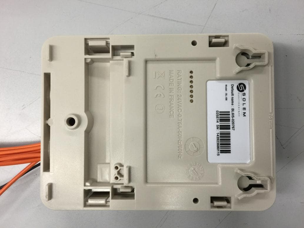
YWW-BLIS
Apr 28, 2015Irrigation Module Sector
Equipment Class
DSS - Part 15 Spread Spectrum Transmitter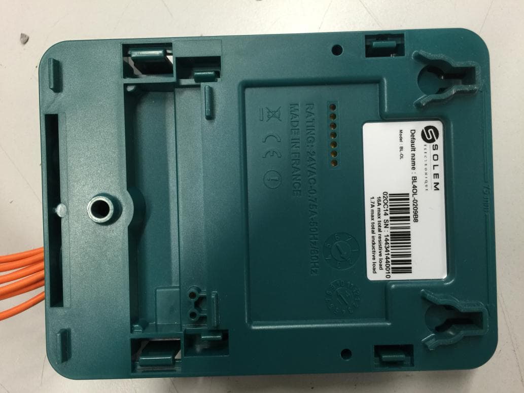
YWW-BLOL
Apr 07, 2015Automatic Devices
Equipment Class
DSS - Part 15 Spread Spectrum Transmitter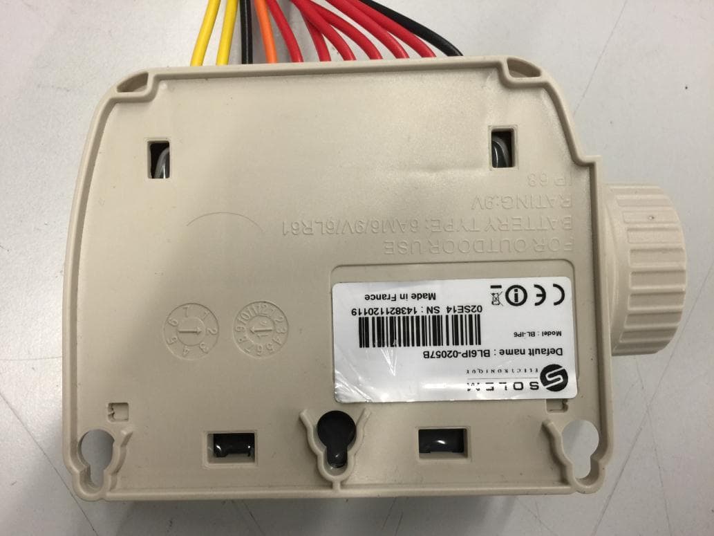
YWW-BLIP
Mar 29, 2015Irrigation Module Battery
Equipment Class
DSS - Part 15 Spread Spectrum Transmitter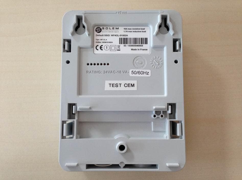
YWW-WFS
Mar 17, 2014Digital Device
Equipment Class
DTS - Digital Transmission System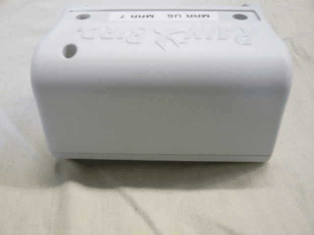
YWW-TBOS2MRRUS1
Jan 17, 2012IQ - TBOS MRR
Equipment Class
DTS - Digital Transmission System