YWW-TBOS2MRRUS1IQ - TBOS MRR
SOLEM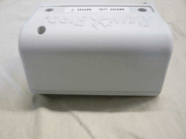
Click to zoom
Application Details
- Equipment Class
- DTS - Digital Transmission System
- Date of Grant
- Jan 17, 2012
- Application Purpose
- Original Equipment
- Date of Application
- Jan 17, 2012
- Equipment Note
- IQ - TBOS MRR
- Frequency Range
- 915.50000000 - 926.50000000
- Company
- SOLEM
- Country
- France
Documents & Files
Document Text
Text extracted from the exhibit documents filed with the FCC. Open a document above to read the original.
Users Manual
Technotes IQ-TBOS Master Radio Module Installation Manual FRANÇAIS - ENGLISH DRAFT – FIELD TEST VERSION October 2011 FCC STATEMENT RF Exposure. STATEMENT DECLARATION FCC Exposition aux radio fréquences DECLARATION This device complies with FCC RF and Industry Canada radiation exposure limits set forth for gener al population. This device must be installed to provide a separation distance of at least 20cm fr om all persons and must not be co-located or oper ating in conjunction with any other antenna or transmitter. Information to user . The user’s manual or instruction manual for an intentional or unintentional radiator shall caution the user that changes or modifications not expressly approved by the party responsible for compliance could void the user's authori ty to operate the equipment. NOTE: This equipment has been tested and found to comply with the limits for a Class B digital device, purs uant to part 15 of the FCC Rules. These limits are designed to provide reasonable pr otection against harmful interference in a residential install ation. This equipment generates, uses and can radiate radio frequency energy and, if not installed and used in accordance with the instruction, may cause harmful interference to radio communic ations. However, there is no guarantee that interference will not occur in a part icul ar install ation. If this equipment does cause harmful interference to radio or television reception which can be determined by turning the equipment off and on, the user is encouraged to try to correct interference by one or more of the fo ll owing measures: - Reorient or relocate the receiving antenna. - Increase the separ ation between the equipment and receiver. - Connect the equipment into an outlet on ci rcuit di fferent fr om that to which the receiver is connected. - Consult the dealer or an experienced radio/TV technician for help. Labeling requirements. This device complies with Part 15 of the FCC Rules. Operation is subject to the following two conditions: (1) This device may not cause harmful interference, and (2) this device must accept any interference received, in cluding interference that may cause undesired oper ation. IC STATEMENT RSS Gen / Transmitter Antenna. Under Industry Canada regulations, this radio transmitt er may only operate using an antenna of a type and maximum (or le sser) gain approved for the tr ansmitter by In dustry Canada. To reduce potential radio interference to other users, the antenna type and its gain should be so chosen that the equivalent is otropically radiated power (e.i.r.p.) is not more than that necessary for successful commun ic ation. This radio tr ansmitter (IC:9319A-TBOS2MRRUS1) has been approved by In dustry Canada to operate with the antenna types li sted below with the maximum permissible gain and required antenna impedance for each antenna type indicated. Antenna types not included in this list, having a gain greater than the maximum gain ind icated for that type, are strictly prohibited for use with this device. List of antennas to be used: - US Antenna: Model: S765FL2-06503 (NEARSON), Gain: 2dBi, Impedance: 50ohms nominal - EU Antenna: Model: S765FL2-06520 (NEARSON), Gain: 2dBi, Impedance: 50ohms nominal RSS Gen / User Manual Notice for Licence-Exempt Radio Apparatus. This device complies with Industry Canada licence-exempt RSS standard(s). Operation is subject to the fo llowing two conditions: (1) this device may not cause interference, and (2) this device must accept any interference, including interference that may cause undesired operation of the device. NORMES CEM (radio) CE : - ETSI EN 300220-2 (V2.3.1-2010/02) and ETSI EN 300220-1 (V2.3.1-2010/02) - EN 50371 (2002) - ETSI EN 301 489-1 (V1.8.1-2008/4) and ETSI EN 301 489-3 (V1.4.1-2002/08) CANADA: - RSS-210 Issue 7- Jun 2007 - RSS-Gen Issue 2- Jun 2007 FCC : - FCC Part 15, Subpart C 15.247 - ANSI C63.4 (2009) Cet équipement peut être utilisé en : FR, MT, BE, CY, PL, CZ, PT, DK, SK, EE, SI, DE, GB, IS, HU, LI, IE, IT, CH, LV, BG, RO, LU, TR. Cet équipement émet des signaux radio dans une bande de fréquence qui n'est pas reconnue ou harmonisée dans les pays suivants: AT, NL, FI, ES, GR, NO, LT, SE. DECLARATION OF CONFORMITY - External power supply need to be certified as Li mited Power Sourc es and compliant with IEC 60950-1, art.2.5. - For equipment remaining connected to the network, an easil y accessible disconnect device must be integrat ed outside the material. In accordance with European Directive 2002/96/EC and EN50419: 2005, this equ ipment must not be disposed of with household waste. It must be collected separ ately to allow its pr oper valuation. By this gesture, you will contribute to environmental pr otection and protection of natural resources. Cet appareil est conforme à la ré glementation FCC concernant les fréquences radio et aux li mites fixées par Industry Canada concernant l’exposition du gr and public aux fréquences radio. Cet appareil doit être installé à une distance d’au moins 20 cm de la population et ne doit pas être localisé au même endroit ou opérer simultanément avec aucune autre antenne ou tr ansmetteur. Information à l’utilisateur. Le manuel d' utilisation ou d'instructions d’un appareil émettant des ondes radio intentionnellement ou non doit pr évenir l' utilisateur que touts changements ou modif ications non expressément approuvés par la partie responsable de la conformité pourraient annuler l'auto rité de l' utilisateur de fa ire fonctionner l'équipement. NOTE: Cet équipement a été testé et approuvé conforme aux limites pour un appareil numérique de classe B, conformément à la partie 15 des rè glements de la FCC. Ces limites sont conçues pour fournir une protection raisonnable contre les interférences nuisibles dans une installation résidentielle. Cet équipement génère, utilise et peut émettre des fr équences radio et, s'il n'est pas installé et utilisé conformément aux instructions, peut pr ovoquer des interférences nuisibles au…
Text truncated - open the document above for the full version.
External Photos
FCC ID: YWW-TBOS2MRRUS1 IC : 9319A-TBOS2MRRUS1 Page 1/7 EXTERNAL PHOTOS OF TESTED EUT General views of ESP/LXME FCC ID: YWW-TBOS2MRRUS1 IC : 9319A-TBOS2MRRUS1 Page 2/7 General views of ESP/LXME FCC ID: YWW-TBOS2MRRUS1 IC : 9319A-TBOS2MRRUS1 Page 3/7 General views of ESP/LXME FCC ID: YWW-TBOS2MRRUS1 IC : 9319A-TBOS2MRRUS1 Page 4/7 General views of antenna FCC ID: YWW-TBOS2MRRUS1 IC : 9319A-TBOS2MRRUS1 Page 5/7 General views of MRR FCC ID: YWW-TBOS2MRRUS1 IC : 9319A-TBOS2MRRUS1 Page 6/7 General views of MRR FCC ID: YWW-TBOS2MRRUS1 IC : 9319A-TBOS2MRRUS1 Page 7/7 General views of MRR
ID Label/Location Info
FCC ID: YWW-TBOS2MRRUS1 IC : 9319A-TBOS2MRRUS1 Page 1/1 PRODUCT LABELING FCC ID / IC number label This is the copy of the label stuck on the product Details of label: - Printer Type = Thermal Transfer - Label Height = 30 mm - Label Width = 20 mm - Polyester Material LABEL
Internal Photos
FCC ID: YWW-TBOS2MRRUS1 IC : 9319A-TBOS2MRRUS1 1 INTERNAL PHOTOS OF EUT General views without cover FCC ID: YWW-TBOS2MRRUS1 IC : 9319A-TBOS2MRRUS1 Detail view FCC ID: YWW-TBOS2MRRUS1 IC : 9319A-TBOS2MRRUS1 Detail view FCC ID: YWW-TBOS2MRRUS1 IC : 9319A-TBOS2MRRUS1 Detail view FCC ID: YWW-TBOS2MRRUS1 IC : 9319A-TBOS2MRRUS1 Detail view
Operational Description
FCC ID: YWW-TBOS2MRRUS1 IC: 9319A-TBOS2MRRUS1 GENERAL INFORMATION 1.1. Product description FCC ID: YWW-TBOS2MRRUS1 IC: 9319A-TBOS2MRRUS1 1.2. Related Submittal(s) / Grant(s) All host equipments used in the test configuration are FCC granted, when relevant. 1.3. Tested System Details The FCC IDs for all equipment, with description of all cables used in the tested system are: - Internal max frequencies: 32MHz • Input/output: - 1 x Connector 10pins - 1 x SMA reverse connector • Auxiliaries used for testing: - 1 x Station ESP/LXME, Sn: 3231670, power supplied (P+N+E) • I/O cables used for testing: - 1 x Antenna cable SMA with antenna, shielded, length: .8m - 1 x Power supply cable, unshielded, length: 2m • Equipment information: - External antenna connector: NO, internal connector for conducted tests. - Radiated fundamental frequency band: [915.5-926.5]MHz, twelve channel - Antenna type: Integral - Stand By mode: Yes - Normal power source: 24VAC supplied by ESP/LXME. - Modulation Type: FSK +/- 140kHz - Modulation Technology: DSSS - Transfer rate: 38400 bps - Maximum Antenna Gain: 2 dBi 1.4. Test Methodology Both conducted and radiated testing were performed according to the procedures in ANSI C63.4-2003, FCC Part 15 Subpart C. Radiated testing was performed at an antenna to EUT distance of 10 meters. During testing, all equipment’s and cables were moved relative to each other in order to identify the worst case set-up. 1.5. Test facility Tests have been performed from December 01 st to 14 th , 2011. This test facility has been fully described in a report and accepted by FCC as compliant with the radiated and AC line conducted test site criteria in ANSI C63.4-2003 in a letter dated March 25 th , 2008 (registration number 94821). This test facility has also been accredited by COFRAC (French accreditation authority for European Union test lab accreditation organization) according to NF EN ISO/IEC 17025, accreditation number 1-1633 as compliant with test site criteria and competence in 47 CFR Part 15/ANSI C63.4 and EN55022/CISPR22 norms for 89/336/EEC European EMC Directive application. All pertinent data for this test facility remains unchanged.
RF Exposure Info
FCCID : YWW-TBOS2MRRUS1 LOW POWER RF EXPOSURE SAMPLE Frequency Range: [915.5-926.5]MHz, 12 channels Low threshold = 60/f(GHz) mW = 60 / 0.915 = 64.7mW Conducted Output Power Measured (dBm) = 6.6dBm Antenna Gain (dBi) = 2dBi EIRP = 7 .3mW Conducted Output Power (mW) = 4. 6mW Since both Conducted Output Power and EIRP are below the low threshold, device complies with FCC and Industry Canada RF radiation exposure limits for general population/uncontrolled exposure as a portable device without SAR evaluation.
Test Report
Rapport d’essai / Test report N° 275414-R4-E JDE : 110612 DELIVRE A / ISSUED TO : SOLEM ZAE LA PLAINE 5 rue Georges Besse 34830 CLAPIERS - FRANCE Objet / Subject : Essais de compatibilité électromagnétique conformément aux normes FCC CFR 47 Part 15, Subpart B et C. Electromagnetic compatibility tests according to the standards FCC CFR 47 Part 15, Subpart B and C Matériel testé / Apparatus under test : • Produit / Product : RF WATERING SYSTEM • Marque / Trade mark : RAIN BIRD • Constructeur / Manufacturer : SOLEM • Type / Model : TBOSII-MRRUS • N° de série / serial number : 7 • FCCID YWW-TBOS2MRRUS1 Date des essais / Test date : Du 1er au 14 Décembre 2011 et 17 Janvier 2012 / From December 01 st to 14 th , 2011 and January 17 th , 2012 Lieu d’essai / Test location : LCIE SUD-EST ZI Centr’Alp – 170 rue de Chatagnon 38430 MOIRANS - FRANCE Test réalisé par / Test performed by : Anthony MERLIN / Nicolas BILLAUD Ce document comporte /Composition of document : 29 pages. M OIRANS, LE 17 JANVIER 2012 / JANUARY 17 TH , 2012 Ecrit par / Written by, Approuvé par / Approved by, Anthony MERLIN Jacques LORQUIN La reproduction de ce document n'est autorisée que sous sa forme intégrale. Toute reproduction partielle ou toute insertion de résultats dans un texte d'accompagnement en vue de leur diffusion doit recevoir un accord préalable et formel du LCIE. Ce document résulte d’essais effectués sur un spécimen, un échantillon ou une éprouvette. Il ne préjuge pas de la conformité de l’ensemble des produits fabriqués à l’objet essayé. Sauf indication contraire, la décision de conformité prend en compte l’incertitude de mesures. Il ne préjuge en aucun cas d’une décision de certification. This document shall not be reproduced, except in full, without t he written approval of the LCIE. This document contains results related only to the item tested. It does not imply the conformity of the whole production to the item tested .Unless otherwise specified; the decision of conformity takes into account the uncertainty of measures. This document does not anticipate any certification decision.. RAPPORT D'ESSAI / TEST REPORT N° 275414-R4-E Page : 2 / 29 SUMMARY 1. TEST PROGRAM ............................................................................................................................... 3 2. SYSTEM TEST CONFIGURATION ..................................................................................................... 4 3. CONDUCTED EMISSION DATA......................................................................................................... 6 4. RADIATED EMISSION DATA ............................................................................................................. 9 5. BANDWIDTH (15.247) ...................................................................................................................... 14 6. MAXIMUM PEAK OUTPUT POWER (15.247) .................................................................................. 16 7. BAND EDGE MEASUREMENT (15.247) .......................................................................................... 18 8. POWER SPECTRAL DENSITY (15.247) .......................................................................................... 21 9. ANNEX 1 (GRAPHS) ........................................................................................................................ 23 10. TEST EQUIPMENT LIST .................................................................................................................. 28 11. UNCERTAINTIES CHART ................................................................................................................ 29 RAPPORT D'ESSAI / TEST REPORT N° 275414-R4-E Page : 3 / 29 1. TEST PROGRAM Standard: - FCC Part 15, Subpart C 15.247 - ANSI C63.4 (2003) EMISSION TEST LIMITS RESULTS (Comments) Limits for conducted disturbance at mains ports 150kHz-30MHz Frequency Quasi-peak value (dBμV) Average value (dBμV) PASS** 150-500kHz 66 to 56 56 to 46 0.5-5MHz 56 46 5-30MHz 60 50 Radiated emissions 9kHz-30MHz Measure at 300m 9kHz-490kHz : 67.6dBμV/m /F(kHz) Measure at 30m 490kHz-1.705MHz : 87.6dBμV/m /F(kHz) 1.705MHz-30MHz : 29.5 dBμV/m PASS Radiated emissions 30MHz-10GHz* Measure at 3m 30MHz-88MHz : 40 dBμV/m 88MHz-216MHz : 43.5 dBμV/m 216MHz-960MHz : 46.0 dBμV/m Above 960MHz : 54.0 dBμV/m PASS Bandwidth 6dB 15.247 (a) (2) At least 500kHz PASS Maximum Peak Output Power 15.247 (b) Limit: 30dBm Conducted or Radiated measurement PASS Band Edge Measurement 15.247 (d) Limit: -20dBc or Radiated emissions limits in restricted bands PASS Power spectral Density 15.247 (e) Limit: 8dBm/3kHz PASS *§15.33: The highest internal source of a testing device is defined like more the highest frequency generated or used in the testing device or on which the testing device works or agrees. - If the highest frequency of the internal sources of the testing device is lower than 108 MHz, measurement must be only performed until 1GHz. - If the highest frequency of the internal sources of the testing device ranges between 108 MHz and 500 MHz, measurement must be only performed until 2GHz. - If the highest frequency of the internal sources of the testing device ranges between 500 MHz and 1 GHz, measurement must be only performed until 5GHz. If the highest frequency of the internal sources of the testing device is above 1 GHz, measurement must be only performed until 5 times the highest frequency or 40 GHz, while taking smallest of both. **: Conducted emission test is the same results that old version of EUT, because there is none modification hardware just add of channel by software. RAPPORT D'ESSAI / TEST REPORT N° 275414-R4-E Page : 4 / 29 2. SYSTEM TEST CONFIGURATION 2.1. JUSTIFICATION The system was configured for testing in a typical fashion (as a customer would normally use it). 2.2. HARDWARE IDENTIFICATION • Equipment under test (EUT): TBOSII-MRRUS Serial number: 7 - Internal max frequencies: 32MHz • Input/output: - 1 x Connector 10pin…
Text truncated - open the document above for the full version.
Test Setup Photos
RAPPORT D'ESSAI / TEST REPORT N° 275414-R4-E Page : 9 / 29 4. RADIATED EMISSION DATA 4.1. CLIMATIC CONDITIONS Test performed by : A.MERLIN / N.BILLAUD Date of test : December 01 st , 2011 and December 06 th , 2011 January 17 th , 2012 Ambient temperature : 24.1C 21.9°C 21°C Relative humidity : 30% 33% 35% 4.2. TEST SETUP The installation of EUT is identical for pre-characterization measurement in a 3 meters semi anechoic chamber and for measures on a 10 meters Open site. MRR in the ESP/LXME station MRR in stand alone
Contact Information
Applicant
Olivier Aussillous
Test Firm
LCIE Sud-EstJacques Lorquin
Technical Specifications
| # | Rule Parts | Frequency Range | Power Output |
|---|---|---|---|
| 1 | 15C | 915.5 MHz - 926.5 MHz | 4.60 mW |
Other Applications from SOLEM
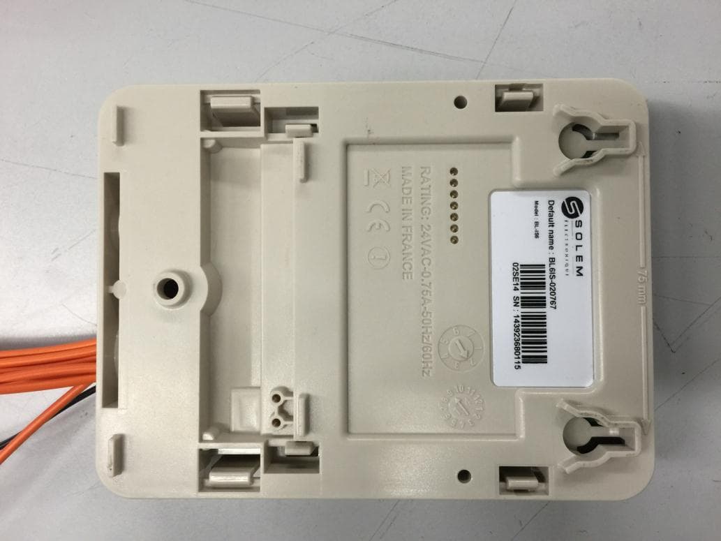
YWW-BLIS
Apr 28, 2015Irrigation Module Sector
Equipment Class
DSS - Part 15 Spread Spectrum Transmitter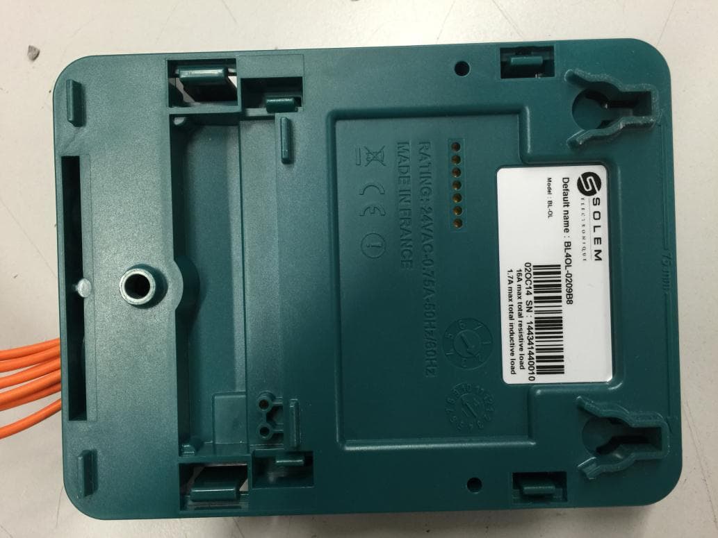
YWW-BLOL
Apr 07, 2015Automatic Devices
Equipment Class
DSS - Part 15 Spread Spectrum Transmitter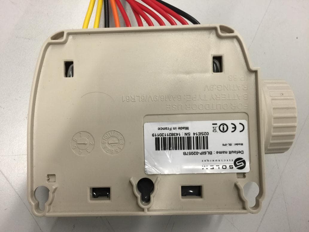
YWW-BLIP
Mar 29, 2015Irrigation Module Battery
Equipment Class
DSS - Part 15 Spread Spectrum Transmitter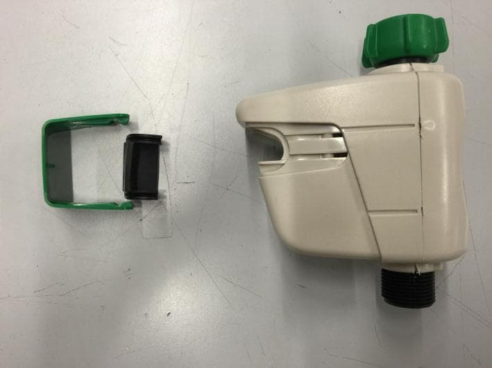
YWW-BLNR
Mar 29, 2015hose end controller
Equipment Class
DSS - Part 15 Spread Spectrum Transmitter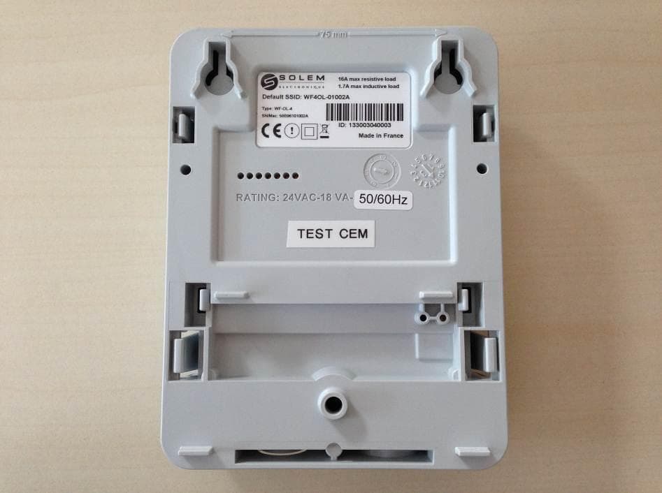
YWW-WFS
Mar 17, 2014Digital Device
Equipment Class
DTS - Digital Transmission System