YWW-BLOLAutomatic Devices
SOLEM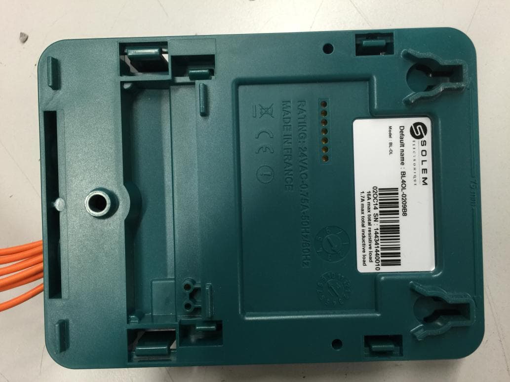
Click to zoom
Application Details
- Equipment Class
- DSS - Part 15 Spread Spectrum Transmitter
- Date of Grant
- Apr 07, 2015
- Application Purpose
- Original Equipment
- Date of Application
- Mar 29, 2015
- Equipment Note
- Automatic Devices
- Frequency Range
- 2402.00000000 - 2480.00000000
- Company
- SOLEM
- Country
- France
Documents & Files
Document Text
Text extracted from the exhibit documents filed with the FCC. Open a document above to read the original.
Users Manual
Page 1/2 LCIE Laboratoire de Moirans Z.I. Centr’Alp 170, Rue de Chatagnon 38430 MOIRANS-FRANCE USER MANUAL (FCC STATEMENT) FCCID: YWW-BLOL This is a copy of the page where the FCC statement is included: NOTICE-60NOTI-BL-OL[-0514-]-WEB Page 2/2 LCIE Laboratoire de Moirans Z.I. Centr’Alp 170, Rue de Chatagnon 38430 MOIRANS-FRANCE
Users Manual
[email protected] +33 467 592 425 www.solem.fr FR P01 EN P11 ES P22 IT P33 BL-OL – Module Automatisme GUIDE D’INSTALLATION RAPIDE INTRODUCTION Les produits BL communiquent avec l’application SolemWF sur smartphone ou tablette en utilisant la technologie Bluetooth SMART 4.0 (Low Energy) présente sur la plupart des nouveaux téléphones (iPhone 4S et supérieur SAMSUNG S3 et supé- rieur, etc...) Assurez-vous que votre appareil soit par conséquent compa- tible avec cette technologie Bluetooth 4.0. Les produits BL permettent de piloter l’arrosage, l’éclairage de jardin ainsi que des pompes de fontaine ou tout autre produit pilotable grâce à un relai à contact sec. Les programmes d’ar- rosage ou d’automatisme sont transmis dans les modules BL à partir de l’application SolemWF disponible gratuitement sur l’App Store ou Google Play (Play Store). L’utilisateur doit d’abord associer son produit BL à son smart- phone ou sa tablette. P-01 1- TELECHARGEZ L’APPLICATION SolemWF Vérifiez que votre appareil est bien connecté à internet (Wi-Fi ou 3G minimum) Téléchargez l’application SolemWF Depuis les plateformes de téléchargement Apple ou Android. P-02 2- ASSOCIATION 1 - A la mise sous tension, le module BL-OL démarre en mode association durant 2 minutes. 2 - Activez le Bluetooth sur votre smartphone en allant dans les réglages. 3 - Lancez l’application SolemWF Au 1 er démarrage de l’application, la page suivante apparait. 4 -Faites glisser votre doigt sur les produits vers la gauche sur l’image des produits pour voir les autres modules , puis appuyer sur l’image qui correspond au module BL-OL que vous souhaitez associer. P-03 Le produit apparait en orange dans la liste des modules détectés par l’application. 5 - Appuyer sur le N° du pro- duit. Ce Numéro correspond au ‘’Default Name’’ présent sur l’étiquette à l’arrière du produit. Important : Vous pouvez changer le nom du module ou ajouter une clé de sécurité pour éviter que tout autre personne à portée radio de votre produit Blue- tooth se connecte et change les données. P-04 6 - Pour changer le nom du module, appuyez sur le N° (comme vu sur p4) Modifiez le nom, puis appuyez sur ̋ Changer ̋. 7 - Pour changer la clé, ap- puyez sur ‘’Clé de Sécurité’’ (comme vu sur p4) Ajoutez un code à 7 chiffres maximum. Appuyez ensuite sur ̋ Changer ̋. 8 - Appuyez sur ̋Associer ̋ pour terminer l’association Votre produit apparait dans la liste des modules associés Si vous avez ajouté une clé, un cadenas apparait en face du nom du module P-05 IMPORTANT: Si vous devez ajouter d’autres modules ou réassocier un pro- duit, il faut maintenant aller sur la page d’accueil et appuyer sur ‘’Ajouter un module’’. Reprenez les instructions d’associations du point N°1, vérifiez bien le N° du produit sur l’étiquette à l’arrière du produit avant de cliquer dessus pour l’associer CAS D’OUBLI DE LA CLE DE SECURITE En cas d’oubli de la clé de sécurité, vous devez débrancher et rebrancher l’alimentation du produit afin qu’il redémarre dans sa phase d’initialisation. Appuyez ensuite sur ‘’Ajouter un module’’ sur l’écran d’accueil et suivez les instructions ci-dessus pour réaffecter une clé 3- PROGRAMMATION La programmation d’automatisme étant intuitive et simple, vous pouvez dès à présent créer vos programmes . Si vous rencontrez des difficultés, connectez vous au site Solem pour vous informer ou envoyez vos questions à : [email protected] P-06 4- FIXATION ET CABLAGE DU MODULE Le produit BL doit être installé uniquement en intérieur et posé contre le mur à l’aide des 2 vis fournies. Câblage du transformateur d’alimentation : - Installer votre produit de telle sorte que le socle de prise de courant soit à proximité du matériel. La prise de courant est un dispositif de sectionnement, en cas de problème, elle doit être aisément accessible à tout moment. - Assurez-vous que la prise de courant sur laquelle votre transformateur d’alimentation est branché présente une protection contre les surintensités et les court circuits de type disjoncteur 16A (20A pour les US). Câblage des lignes de commande: - Un dispositif de sectionnement doit être prévu dans l’installation du bâti- ment pour chacune des lignes commandées, identifié et directement acces- sible. - Les câbles 230V (120V pour les US) qui sont utilisés pour piloter les 4 lignes du produit doivent présenter une double isolation ou une isolation renforcée. - Les câbles à utiliser doivent être des câbles souples gainés de type H05VV-F ou H03VV-F de section 2x1,5mm². Charges Maximales : Installation 230V : 4000W (16A*) réparties sur l’ensemble des lignes, et jusqu’à uniquement 3500W sur une ligne. Installation 120V : 2000W (16A*) réparties sur l’ensemble des lignes, et jusqu’à uniquement 1700W sur une ligne. Utiliser uniquement le bloc alimentation fourni avec le produit 120V 0.75A *16 A max pour une charge résistive 1.7A max pour une charge inductive Température ambiante maximale d’utilisation du produit : 45°C P-07 Ø6mm 75mm P-08 Les brides doivent être montées même pour les lignes non cablées Alimentation 24Vac, 0.75A transformateur Phase Neutre 5- INFORMATIONS COMPLEMENTAIRES Configuration Requise iOS 7 Minimum : iPhone 4S et supérieur, iPad 3 et supérieur, iPod Touch 5. Android 4.3 Minimum : Samsung S3 et supérieur / Note 2 / Google Nexus 7 2013 / Sony Xperia Z, Z1 Tout appareil comportant un niveau de Bluetooth Smart 4.0 Résolution de problèmes Pas de communication ou aucun module détecté Pas d’action Décalage des programmes Vérifier que vous avez bien activé le Blue- tooth du téléphone et vérifier que vous avez activé la recherche des produits BL. Vérifier l’alimentation Vérifier le cablage Le module a perdu l’heure suite a une coupure secteur, resynchroniser avec l’ application Signification de la LED sur la face avant du module Etat de la LedSignification Rouge fixe pendant 2mn 2 x Flash rouge Mode installation, module en attente de configuration initiale à la première installation. Suite coupure secteur, le module a perdu…
Text truncated - open the document above for the full version.
External Photos
Page 1/7 LCIE Laboratoire de Moirans Z.I. Centr’Alp 170, Rue de Chatagnon 38430 MOIRANS-FRANCE EXTERNAL PHOTOS OF EQUIPMENT FCCID: YWW-BLOL Page 2/7 LCIE Laboratoire de Moirans Z.I. Centr’Alp 170, Rue de Chatagnon 38430 MOIRANS-FRANCE Page 3/7 LCIE Laboratoire de Moirans Z.I. Centr’Alp 170, Rue de Chatagnon 38430 MOIRANS-FRANCE Page 4/7 LCIE Laboratoire de Moirans Z.I. Centr’Alp 170, Rue de Chatagnon 38430 MOIRANS-FRANCE Page 5/7 LCIE Laboratoire de Moirans Z.I. Centr’Alp 170, Rue de Chatagnon 38430 MOIRANS-FRANCE Page 6/7 LCIE Laboratoire de Moirans Z.I. Centr’Alp 170, Rue de Chatagnon 38430 MOIRANS-FRANCE Page 7/7 LCIE Laboratoire de Moirans Z.I. Centr’Alp 170, Rue de Chatagnon 38430 MOIRANS-FRANCE
ID Label/Location Info
Page 1/1 LCIE Laboratoire de Moirans Z.I. Centr’Alp 170, Rue de Chatagnon 38430 MOIRANS-FRANCE PRODUCT LABELING FCCID: YWW-BLOL Manufacturer: BRADY Label: THT.17 - 483 -3 B-483 Overall dimensions 50.8 x 25.4 mm @ 0.102 mm thickness Ink: R-4900 Impression type: THERMIQUE
Internal Photos
Page 1/8 LCIE Laboratoire de Moirans Z.I. Centr’Alp 170, Rue de Chatagnon 38430 MOIRANS-FRANCE INTERNAL PHOTOS OF EQUIPMENT FCCID: YWW-BLOL Page 2/8 LCIE Laboratoire de Moirans Z.I. Centr’Alp 170, Rue de Chatagnon 38430 MOIRANS-FRANCE Page 3/8 LCIE Laboratoire de Moirans Z.I. Centr’Alp 170, Rue de Chatagnon 38430 MOIRANS-FRANCE Page 4/8 LCIE Laboratoire de Moirans Z.I. Centr’Alp 170, Rue de Chatagnon 38430 MOIRANS-FRANCE Page 5/8 LCIE Laboratoire de Moirans Z.I. Centr’Alp 170, Rue de Chatagnon 38430 MOIRANS-FRANCE Page 6/8 LCIE Laboratoire de Moirans Z.I. Centr’Alp 170, Rue de Chatagnon 38430 MOIRANS-FRANCE Page 7/8 LCIE Laboratoire de Moirans Z.I. Centr’Alp 170, Rue de Chatagnon 38430 MOIRANS-FRANCE Page 8/8 LCIE Laboratoire de Moirans Z.I. Centr’Alp 170, Rue de Chatagnon 38430 MOIRANS-FRANCE
Operational Description
LCIE Laboratoire de Moirans Z.I. Centr’Alp 170, Rue de Chatagnon 38430 MOIRANS-FRANCE GENERAL INFORMATION FCCID: YWW-BLOL 1.1. Product description LCIE Laboratoire de Moirans Z.I. Centr’Alp 170, Rue de Chatagnon 38430 MOIRANS-FRANCE LCIE Laboratoire de Moirans Z.I. Centr’Alp 170, Rue de Chatagnon 38430 MOIRANS-FRANCE 1.2. Tested System Details Photography of EUT Power supply: During all the tests, EUT is supplied by V nom : 24VAC For measurement with different voltage, it will be presented in test method. Name Type Rating Reference / Sn Comments Supply1 AC DC Battery LCIE Laboratoire de Moirans Z.I. Centr’Alp 170, Rue de Chatagnon 38430 MOIRANS-FRANCE Inputs/outputs - Cable: Access Type Length used (m) Declared <3m Shielded Under test Comments Supply1 AC 3 - Access1 USB 1 Temporary USB installed for the reception of different orders (power, choice of channel, modulation etc.) Access2 I/O 0.5 - Access3 I/O 0.5 - Access4 I/O 0.5 - Access5 I/O 0.5 - Auxiliary equipment used during test: Type Reference Sn Comments Laptop ThinkPad Tseries L3-B746308/01 - Equipment information: Type: Bluetooth Low Energy v4.0 Frequency band: [2400 – 2483.5] MHz Sub-band REC7003: Annex 3 (a) Spectrum Modulation: DSSS (Tested like it) Number of Channel: 40 Spacing channel: 2MHz Channel bandwidth: 1MHz Transmit chains: 1 2 3 4 Single antenna Symmetrical Asymmetrical Gain 1: 3dBi Gain 2: dBi Gain 3: dBi Gain 4: dBi Beam forming gain: Yes: dB No Receiver chains 1 2 3 4 Type of equipment: Stand-alone Plug-in Combined Ad-Hoc mode: Yes No Adaptivity mode: Yes (Load Based) Off mode No Clear Channel Assessment Time: None q value for Load Based Equipment: None Duty cycle: Continuous duty Intermittent duty Continuous operation Equipment type: Production model Prototype Chip Reference: nRF51822 By Nordic Semiconductor Temperature range: Tmin: -20°C 0°C °C Tnom: 20°C Tmax: 35°C 55°C °C Test source voltage: AC: 24 DC: Battery: LCIE Laboratoire de Moirans Z.I. Centr’Alp 170, Rue de Chatagnon 38430 MOIRANS-FRANCE 1.1. EUT CONFIGURATION The EUT is set in the following modes during tests with simulator / software (v1.93b): “Terminal” - Permanent emission with modulation on a fixed channel in the data rate that produced the highest power - Permanent reception - The Power order sent for the Module is set at 0dBm. LCIE Laboratoire de Moirans Z.I. Centr’Alp 170, Rue de Chatagnon 38430 MOIRANS-FRANCE 1.2. Equipment modification None Modification: The capacity C22 (1pF) between antenna and C15 (capacity) is removed, see following map: 1.3. Test Methodology Both conducted and radiated testing were performed according to the procedures in ANSI C63.4-2003, FCC Part 15 Subpart C. Radiated testing was performed at an antenna to EUT distance of 10 meters. During testing, all equipment’s and cables were moved relative to each other in order to identify the worst case set-up. 1.4. Test facility Tests have been performed on from November 17th to 26th, 2014. LCIE Laboratoire de Moirans Z.I. Centr’Alp 170, Rue de Chatagnon 38430 MOIRANS-FRANCE This test facility has been fully described in a report and accepted by FCC as compliant with the radiated and AC line conducted test site criteria in ANSI C63.4-2003 in a letter dated March 25 th , 2008 (registration number 94821). This test facility has also been accredited by COFRAC (French accreditation authority for European Union test lab accreditation organization) according to NF EN ISO/IEC 17025, accreditation number 1-1633 as compliant with test site criteria and competence in 47 CFR Part 15/ANSI C63.4 and EN55022/CISPR22 norms for 89/336/EEC European EMC Directive application. All pertinent data for this test facility remains unchanged.
RF Exposure Info
LCIE Laboratoire de Moirans Z.I. Centr’Alp 170, Rue de Chatagnon 38430 MOIRANS-FRANCE FCCID: YWW-BLOL Prediction of MPE limit at a given distance Equation from page 18 of OET Bulletin 65, Edition 97-01 where:S = power density P = power input to the antenna G = power gain of the antenna in the direction of interest relative to an isotropic radiator R = distance to the center of radiation of the antenna Prediction Frequency MHz Conducted Output Power dBm Max Antenna Gain dBi Distance cm Power Density mW/cm2 Limit mW/cm2 24020.163200.00041.00 24420.633200.00051.00 24800.823200.00051.00 Conclusion: Therefore our device complies with FCC’s RF radiation exposure limits for general population without SAR evaluation with at least 20cm separation from all persons and must not be co-located or operating in conjunction with any other antenna or transmitter.
Test Report
This document shall not be reproduced, except in full, without the written approval of the LCIE. This document contains results related only to the item tested. It does not imply the conformity of the whole production to the item tested .Unless otherwise specified; the decision of conformity takes into account the uncertainty of measures. This document does not anticipate any certification decision. TEST REPORT N°: 810529-A1-R6-E JDE : 132065 Subject Electromagnetic compatibility and Radio spectrum Matters (ERM) tests according to standards: FCC CFR 47 Part 15, Subpart B et C RSS-210 Issue 8 Issued to SOLEM ZAE la Plaine 5 rue Georges Besses. 34830 - CLAPIER Apparatus under test Product Automatic Devices Trade mark SOLEM Manufacturer SOLEM Model under test BL-OL Serial number BL4OL-0209B7 FCCID YWW-BLOL ICID 9319A-BLOL Test date From December 8 th to 24 th , 2014 Test location Moirans Test performed by G.Deschamps / M.Mourzagh Composition of document 33 pages Modification of the last version None Document issued on February 18th, 2015 Written by : Approved by : Gaëtan Deschamps Anthony Merlin Tests operator Technical manager TEST REPORT N°810529-A1-R6-E Page 2/33 SUMMARY 1. TEST PROGRAM ............................................................................................................................... 3 2. SYSTEM TEST CONFIGURATION ..................................................................................................... 4 3. CONDUCTED EMISSION DATA......................................................................................................... 8 4. RADIATED EMISSION DATA ........................................................................................................... 10 5. BANDWIDTH (15.247) ...................................................................................................................... 14 6. MAXIMUM PEAK OUTPUT POWER (15.247) .................................................................................. 16 7. POWER SPECTRAL DENSITY (15.247) .......................................................................................... 19 8. BAND EDGE MEASUREMENT (15.247) .......................................................................................... 22 9. OCCUPIED BANDWIDTH ................................................................................................................. 27 10. ANNEX 1 (GRAPHS) ........................................................................................................................ 29 11. ANNEX 2 (GRAPHS) ........................................................................................................................ 31 12. UNCERTAINTIES CHART ................................................................................................................ 33 TEST REPORT N°810529-A1-R6-E Page 3/33 1. TEST PROGRAM Standard: - FCC Part 15, Subpart C 15.247 - ANSI C63.4 (2003) - RSS-210 Issue 8 – Dec 2010 - RSS-Gen Issue 3 – Dec 2010 EMISSION TEST LIMITS RESULTS Limits for conducted disturbance at mains ports 150kHz-30MHz Frequency Quasi-peak value (dBμV) Average value (dBμV) PASS FAIL NA NP 150-500kHz 66 to 56 56 to 46 0.5-5MHz 56 46 5-30MHz 60 50 Radiated emissions 9kHz-30MHz CFR 47 §15.209 (a) CFR 47 §15.247 (d) RSS-210 §A8.5 Measure at 300m 9kHz-490kHz : 67.6dBμV/m /F(kHz) Measure at 30m 490kHz-1.705MHz : 87.6dBμV/m /F(kHz) 1.705MHz-30MHz : 29.5 dBμV/m PASS FAIL NA NP Radiated emissions 30MHz-25GHz* CFR 47 §15.209 (a) CFR 47 §15.247 (d) RSS-210 §A8.5 Highest frequency : (Declaration of provider) Measure at 3m 30MHz-88MHz : 40 dBμV/m 88MHz-216MHz : 43.5 dBμV/m 216MHz-960MHz : 46.0 dBμV/m Above 960MHz : 54.0 dBμV/m PASS FAIL NA NP Bandwidth 6dB CFR 47 §15.247 (a) (2) RSS-210 §A8.2 At least 500kHz PASS FAIL NA NP Maximum Peak Output Power CFR 47 §15.247 (b) RSS-210 §A8.4 (4) Limit: 30dBm Conducted or Radiated measurement PASS FAIL NA NP Band Edge Measurement CFR 47 §15.209 (a) CFR 47 §15.247 (d) RSS-210 §A8.5 Limit: -20dBc or Radiated emissions limits in restricted bands PASS FAIL NA NP Power spectral Density CFR 47 §15.247 (e) RSS-210 §A8.2 Limit: 8dBm/3kHz PASS FAIL NA NP Occupied bandwidth RSS-Gen §4.6.1 No limit PASS FAIL NA NP Receiver Spurious Emission** RSS-Gen §4.10 See RSS-Gen §4.10 PASS FAIL NA NP *§15.33: The highest internal source of a testing device is defined like more the highest frequency generated or used in the testing device or on which the testing device works or agrees. - If the highest frequency of the internal sources of the testing device is lower than 108 MHz, measurement must be only performed until 1GHz. - If the highest frequency of the internal sources of the testing device ranges between 108 MHz and 500 MHz, measurement must be only performed until 2GHz. - If the highest frequency of the internal sources of the testing device ranges between 500 MHz and 1 GHz, measurement must be only performed until 5GHz. If the highest frequency of the internal sources of the testing device is above 1 GHz, measurement must be only performed until 5 times the highest frequency or 40 GHz, while taking smallest of both. TEST REPORT N°810529-A1-R6-E Page 4/33 2. SYSTEM TEST CONFIGURATION 2.1. HARDWARE IDENTIFICATION (EUT AND AUXILIARIES): Equipment under test (EUT): BL-OL Serial Number: BL4OL-0209B7 Photography of EUT Power supply: During all the tests, EUT is supplied by V nom : 24VAC For measurement with different voltage, it will be presented in test method. Name Type Rating Reference / Sn Comments Supply1 AC DC Battery TEST REPORT N°810529-A1-R6-E Page 5/33 Inputs/outputs - Cable: Access Type Length used (m) Declared <3m Shielded Under test Comments Supply1 AC 3 - Access1 USB 1 Temporary USB installed for the reception of different orders (power, choice of channel, modulation etc.) Access2 I/O 0.5 - Access3 I/O 0.5 - Access4 I/O 0.5 …
Text truncated - open the document above for the full version.
Test Setup Photos
Page 1/2 LCIE Laboratoire de Moirans Z.I. Centr’Alp 170, Rue de Chatagnon 38430 MOIRANS-FRANCE CONDUCTED AND RADIATED MEASUREMENT PHOTO FCCID: YWW-BLOL 1.1 Conducted 1.2 Radiated emissions Page 2/2 LCIE Laboratoire de Moirans Z.I. Centr’Alp 170, Rue de Chatagnon 38430 MOIRANS-FRANCE
Contact Information
Applicant
Olivier Aussillous
Test Firm
LCIE Sud-EstJacques Lorquin
Technical Specifications
| # | Rule Parts | Frequency Range | Power Output |
|---|---|---|---|
| 1 | 15C | 2.40 GHz - 2.48 GHz | 1.20 mW |
Other Applications from SOLEM
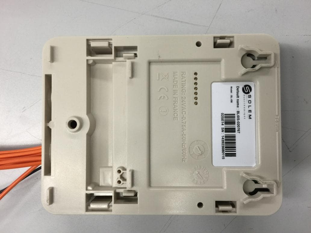
YWW-BLIS
Apr 28, 2015Irrigation Module Sector
Equipment Class
DSS - Part 15 Spread Spectrum Transmitter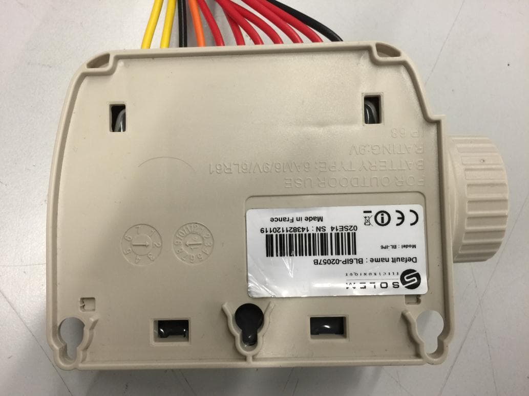
YWW-BLIP
Mar 29, 2015Irrigation Module Battery
Equipment Class
DSS - Part 15 Spread Spectrum Transmitter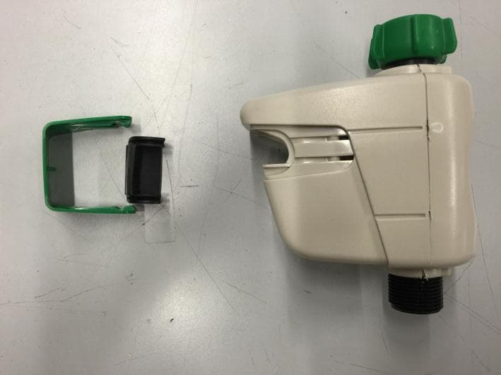
YWW-BLNR
Mar 29, 2015hose end controller
Equipment Class
DSS - Part 15 Spread Spectrum Transmitter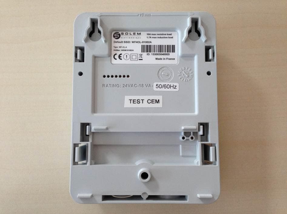
YWW-WFS
Mar 17, 2014Digital Device
Equipment Class
DTS - Digital Transmission System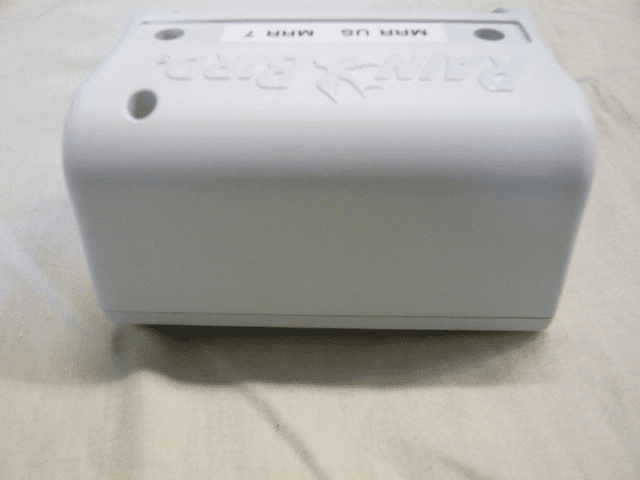
YWW-TBOS2MRRUS1
Jan 17, 2012IQ - TBOS MRR
Equipment Class
DTS - Digital Transmission System