YWW-TBOS2SRRUS1TBOS Radio Relay
SOLEM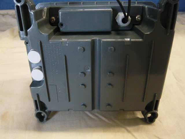
Click to zoom
Application Details
- Equipment Class
- DTS - Digital Transmission System
- Date of Grant
- Jan 12, 2012
- Application Purpose
- Original Equipment
- Date of Application
- Jan 12, 2012
- Equipment Note
- TBOS Radio Relay
- Frequency Range
- 915.50000000 - 926.50000000
- Company
- SOLEM
- Country
- France
Documents & Files
Document Text
Text extracted from the exhibit documents filed with the FCC. Open a document above to read the original.
Users Manual
TBOS Radio Relay Installation Manual FRANÇAIS ENGLISH DRAFT – Field Test Version - Oct 2011 ENGLISH Important! This device TBOS Radio Relay must be fixed to the wall with the enclosed wall fastener. Different wall materials require different types of fixing devices. Use fixing devices suitable for the walls in your home (not included). If you are uncertain about what type of screw or fitting to use, please contact your hardware store. DEUTSCH Achtung! Dieses TBOS Radio Relay muss mit der beigepackten andbefestigung an der Wand angebracht werden. Verschiedene Materialien erfordern verschiedene Arten von Befestigungsbeschlägen. Immer Befestigungsmaterial verwenden, das für die häuslichen Wände geeignet ist (nicht beigepackt). Gfs. sollte man sich beim Eisenwarenfachhandel nach geeignetem Befestigungsmaterial FRANÇAIS Attention ! Cet appareil TBOS Radio Relay doit être fixé à l’aide des accessoires de fixation fournis. Dans le cas de fixation sur un mur vertical ou horizontal, les vis et les chevilles (non fournies) doivent être adaptées au matériau de votre mur. En cas de doute, demandez conseil à un vendeur spécialisé. NEDERLANDS Belangrijk! Bevestig dit TBOS Radio Relay met het meegeleverde muuranker aan de muur.Verschillende wandmaterialen vereisen verschillende soorten bevestigingsbeslag.Gebruik bevestigingsbeslag dat geschikt is voor de muren in je huis (niet inbegrepen).Weet je niet precies welke soort schroeven/beslag je moet gebruiken,neem contact op met de vakhandel. ITALIANO Importante! Questo TBOS Radio Relay deve essere fissato alla parete con l’apposito accessorio incluso. Pareti di materiali diversi richiedono tipi diversi di accessori di fissaggio. Usa sempre accessori di fissaggio (da acquistare a parte) adatti alle pareti della tua casa. Se hai dubbi, rivolgiti a un rivenditore specializzato. ESPAÑOL Importante! Este TBOS Radio Relay debe fijarse a la pared con el dispositivo que se suministra. Distintos materiales de pared requieren distintos tipos de herrajes de fijación. Usa herrajes de fijación adecuados para las paredes de tu casa (no se incluyen). Si no estás seguro sobre el tipo de tornillo o herraje, pregunta en tu ferretería habitual. PORTUGUES Importante! Este TBOS Radio Relay deve ser fixo à parede com o dispositivo incluído. Diferentes materiais de parede requerem diferentes tipos de ferragens de fixação. Use ferragens de fixação adequadas para as paredes da sua casa (não incluídas). Se não tiver a certeza sobre o tipo de parafusos ou ferragem a usar, dirija- se a uma loja especializada. POLSKI Ważne! TBOS Radio Relay należy przytwierdzić do ściany za pomocą specjalnego elementu dołączonego do zestawu. Różne materiały wymagają różnych typów mocującowań. Korzystaj z produktów (nie będących częścią zestawu) odpowiednich do typu ścian wTwoim domu. W przypadku wątpliwości zwróć się o poradę do najbliższego sklepu specjalistycznego. SLOVENSKY Dôležité! Tento TBOS Radio Relay je nutné upevniť k stene pomocou priloženého nástenného kovania. Steny bývajú z rôznych materiálov, preto vyžadujú rôzne typy spojovacieho materiálu. Vyberte si taký spojovací materiál, ktorý je vhodný na vašu stenu(nie je súčasťou balenia). Ak si nie ste istí, aké skrutky a spojovací materiál mate použiť, kontaktujte najbližší špecializovaný obchod. FCC STATEMENT RF Exposure. STATEMENT DECLARATION FCC Exposition aux Fréquences Radio DECLARATION This device complies with FCC RF and Industry Canada radiation exposure limits set forth for general population. This device must be installed to provide a separation distance of at least 20cm from all persons and must not be co-located or operating in conjunction with any other antenna or transmitter. I information to user. The user’s manual or instruction manual for an intentional or unintentional radiator shall caution the user that changes or modifications not expressly approved by the party responsible for compliance could void the user's authority to operate the equipment. NOTE: This equipment has been tested and found to comply with the limits for a Class B digital device, pursuant to part 15 of the FCC Rules. These limits are designed to provide reasonable protection against harmful interference in a residential installation. This equipment generates, uses and can radiate radio frequency energy and, if not installed and used in accordance with the instruction, may cause harmful interference to radio communications. However, there is no guarantee that interference will not occur in a particular installation. If this equipment does cause harmful interference to radio or television reception which can be determined by turning the equipment off and on, the user is encouraged to try to correct interference by one or more of the following measures: - Reorient or relocate the receiving antenna. - Increase the separation between the equipment and receiver. - Connect the equipment into an outlet on circuit different from that to which the receiver is connected. - Consult the dealer or an experienced radio/TV technician for help. Labeling requirements. This device complies with Part 15 of the FCC Rules. Operation is subject to the following two conditions: (1) This device may not cause harmful interference, and (2) this device must accept any interference received, including interference that may cause undesired operation. I C STATEMENT RSS Gen / Transmitter Antenna. Under Industry Canada regulations, this radio transmitter may only operate using an antenna of a type and maximum (or lesser) gain approved for the transmitter by Industry Canada. To reduce potential radio interference to other users, the antenna type and its gain should be so chosen that the equivalent isotropically radiated power (e.i.r.p.) is not more than that necessary for successful communication. RSS Gen / User Manual Notice for Licence-Exempt Radio Apparatus. This device complies with Industry Canada licence-exempt RSS standard(s). Operation is subject to the following two conditions: …
Text truncated - open the document above for the full version.
External Photos
FCC ID: YWW-TBOS2SRRUS1 IC : 9319A-TBOS2SRRUS1 Page 1/4 EXTERNAL PHOTOS OF TESTED EUT FCC ID: YWW-TBOS2SRRUS1 IC : 9319A-TBOS2SRRUS1 Page 2/4 FCC ID: YWW-TBOS2SRRUS1 IC : 9319A-TBOS2SRRUS1 Page 3/4 FCC ID: YWW-TBOS2SRRUS1 IC : 9319A-TBOS2SRRUS1 Page 4/4
ID Label/Location Info
FCC ID: YWW-TBOS2SRRUS1 IC: 9319A-TBOS2SRRUS1 Page 1/2 PRODUCT LABELING FCC ID / IC number label This is the copy of the label stuck on the product Details of label: - Printer Type = Thermal Transfer - Label Height = 30 mm - Label Width = 20 mm - Polyester Material LABEL FCC ID: YWW-TBOS2SRRUS1 IC: 9319A-TBOS2SRRUS1 Page 2/2
Internal Photos
FCC ID: YWW-TBOS2SRRUS1 IC : 9319A-TBOS2SRRUS1 1 INTERNAL PHOTOS OF EUT Without cover FCC ID: YWW-TBOS2SRRUS1 IC : 9319A-TBOS2SRRUS1 Without cover FCC ID: YWW-TBOS2SRRUS1 IC : 9319A-TBOS2SRRUS1 General view of PCB and antenna FCC ID: YWW-TBOS2SRRUS1 IC : 9319A-TBOS2SRRUS1 Detail views of PCB FCC ID: YWW-TBOS2SRRUS1 IC : 9319A-TBOS2SRRUS1 Detail views of PCB FCC ID: YWW-TBOS2SRRUS1 IC : 9319A-TBOS2SRRUS1 General view of PCB FCC ID: YWW-TBOS2SRRUS1 IC : 9319A-TBOS2SRRUS1 Detail views of PCB FCC ID: YWW-TBOS2SRRUS1 IC : 9319A-TBOS2SRRUS1 Detail views of PCB FCC ID: YWW-TBOS2SRRUS1 IC : 9319A-TBOS2SRRUS1 View of battery
Operational Description
FCC ID: YWW-TBOS2SRRUS1 IC: 9319A-TBOS2SRRUS1 GENERAL INFORMATION 1.1. Product description FCC ID: YWW-TBOS2SRRUS1 IC: 9319A-TBOS2SRRUS1 FCC ID: YWW-TBOS2SRRUS1 IC: 9319A-TBOS2SRRUS1 1.2. Related Submittal(s) / Grant(s) All host equipments used in the test configuration are FCC granted, when relevant. 1.3. Tested System Details The FCC IDs for all equipment, with description of all cables used in the tested system are: - Internal max frequencies: 32MHz • Input/output: - 1 x Power supply, 2 wires unshielded, 12VAC • Auxiliaries used for testing: - None • I/O cables used for testing: - 2 x wires unshielded, length: 2m • Equipment information: - External antenna connector: NO, special EUT with connector for conducted tests. - Radiated fundamental frequency band: [915.5-926.5]MHz, twelve channel - Antenna type: Integral - Stand By mode: Yes - Normal power source: 12VAC and internal lead battery 6VDC. - Modulation Type: FSK +/- 140kHz - Modulation Technology: DSSS - Transfer rate: 38400 bps - Maximum Antenna Gain: 0 dBi 1.4. Test Methodology Both conducted and radiated testing were performed according to the procedures in ANSI C63.4-2003, FCC Part 15 Subpart C. Radiated testing was performed at an antenna to EUT distance of 10 meters. During testing, all equipment’s and cables were moved relative to each other in order to identify the worst case set-up. 1.5. Test facility Tests have been performed from December 01 st to 14 th , 2011. This test facility has been fully described in a report and accepted by FCC as compliant with the radiated and AC line conducted test site criteria in ANSI C63.4-2003 in a letter dated March 25 th , 2008 (registration number 94821). This test facility has also been accredited by COFRAC (French accreditation authority for European Union test lab accreditation organization) according to NF EN ISO/IEC 17025, accreditation number 1-1633 as compliant with test site criteria and competence in 47 CFR Part 15/ANSI C63.4 and EN55022/CISPR22 norms for 89/336/EEC European EMC Directive application. All pertinent data for this test facility remains unchanged.
RF Exposure Info
FCCID : YWW-TBOS2SRRUS1 LOW POWER RF EXPOSURE SAMPLE Frequency Range: [915.5-926.5]MHz, 12 channels Low threshold = 60/f(GHz) mW = 60 / 0.915 = 64.7mW Conducted Output Power Measured (dBm) = 7.3dBm Antenna Gain (dBi) = 0dBi EIRP = 5.4mW Conducted Output Power (mW) = 5.4mW Since both Conducted Output Power and EIRP are below the low threshold, device complies with FCC and Industry Canada RF radiation exposure limits for general population/uncontrolled exposure as a portable device without SAR evaluation.
Test Report
Rapport d’essai / Test report N° 275414-R3-E JDE : 110612 DELIVRE A / ISSUED TO : SOLEM ZAE LA PLAINE 5 rue Georges Besse 34830 CLAPIERS - FRANCE Objet / Subject : Essais de compatibilité électromagnétique conformément aux normes FCC CFR 47 Part 15, Subpart B et C. Electromagnetic compatibility tests according to the standards FCC CFR 47 Part 15, Subpart B and C Matériel testé / Apparatus under test : • Produit / Product : RF WATERING SYSTEM • Marque / Trade mark : RAIN BIRD • Constructeur / Manufacturer : SOLEM • Type / Model : TBOSII-SRRUS • N° de série / serial number : 9 • FCCID YWW-TBOS2SRRUS1 Date des essais / Test date : Du 1er au 14 Décembre 2011 / From December 01 st to 14 th , 2011 Lieu d’essai / Test location : LCIE SUD-EST ZI Centr’Alp – 170 rue de Chatagnon 38430 MOIRANS - FRANCE Test réalisé par / Test performed by : Anthony MERLIN / Nicolas BILLAUD Ce document comporte /Composition of document : 28 pages. M OIRANS, LE 9 JANVIER 2012 / JANUARY 9 TH , 2012 Ecrit par / Written by, Approuvé par / Approved by, Anthony MERLIN Jacques LORQUIN La reproduction de ce document n'est autorisée que sous sa forme intégrale. Toute reproduction partielle ou toute insertion de résultats dans un texte d'accompagnement en vue de leur diffusion doit recevoir un accord préalable et formel du LCIE. Ce document résulte d’essais effectués sur un spécimen, un échantillon ou une éprouvette. Il ne préjuge pas de la conformité de l’ensemble des produits fabriqués à l’objet essayé. Sauf indication contraire, la décision de conformité prend en compte l’incertitude de mesures. Il ne préjuge en aucun cas d’une décision de certification. This document shall not be reproduced, except in full, without t he written approval of the LCIE. This document contains results related only to the item tested. It does not imply the conformity of the whole production to the item tested .Unless otherwise specified; the decision of conformity takes into account the uncertainty of measures. This document does not anticipate any certification decision. RAPPORT D'ESSAI / TEST REPORT N° 275414-R3-E Page : 2 / 28 SUMMARY 1. TEST PROGRAM ............................................................................................................................... 3 2. SYSTEM TEST CONFIGURATION ..................................................................................................... 4 3. CONDUCTED EMISSION DATA......................................................................................................... 6 4. RADIATED EMISSION DATA ............................................................................................................. 9 5. BANDWIDTH (15.247) ...................................................................................................................... 13 6. MAXIMUM PEAK OUTPUT POWER (15.247) .................................................................................. 15 7. BAND EDGE MEASUREMENT (15.247) .......................................................................................... 17 8. POWER SPECTRAL DENSITY (15.247) .......................................................................................... 20 9. ANNEX 1 (GRAPHS) ........................................................................................................................ 22 10. TEST EQUIPMENT LIST .................................................................................................................. 27 11. UNCERTAINTIES CHART ................................................................................................................ 28 RAPPORT D'ESSAI / TEST REPORT N° 275414-R3-E Page : 3 / 28 1. TEST PROGRAM Standard: - FCC Part 15, Subpart C 15.247 - ANSI C63.4 (2003) EMISSION TEST LIMITS RESULTS (Comments) Limits for conducted disturbance at mains ports 150kHz-30MHz Frequency Quasi-peak value (dBμV) Average value (dBμV) PASS** 150-500kHz 66 to 56 56 to 46 0.5-5MHz 56 46 5-30MHz 60 50 Radiated emissions 9kHz-30MHz Measure at 300m 9kHz-490kHz : 67.6dBμV/m /F(kHz) Measure at 30m 490kHz-1.705MHz : 87.6dBμV/m /F(kHz) 1.705MHz-30MHz : 29.5 dBμV/m PASS Radiated emissions 30MHz-10GHz* Measure at 3m 30MHz-88MHz : 40 dBμV/m 88MHz-216MHz : 43.5 dBμV/m 216MHz-960MHz : 46.0 dBμV/m Above 960MHz : 54.0 dBμV/m PASS Bandwidth 6dB 15.247 (a) (2) At least 500kHz PASS Maximum Peak Output Power 15.247 (b) Limit: 30dBm Conducted or Radiated measurement PASS Band Edge Measurement 15.247 (d) Limit: -20dBc or Radiated emissions limits in restricted bands PASS Power spectral Density 15.247 (e) Limit: 8dBm/3kHz PASS *§15.33: The highest internal source of a testing device is defined like more the highest frequency generated or used in the testing device or on which the testing device works or agrees. - If the highest frequency of the internal sources of the testing device is lower than 108 MHz, measurement must be only performed until 1GHz. - If the highest frequency of the internal sources of the testing device ranges between 108 MHz and 500 MHz, measurement must be only performed until 2GHz. - If the highest frequency of the internal sources of the testing device ranges between 500 MHz and 1 GHz, measurement must be only performed until 5GHz. If the highest frequency of the internal sources of the testing device is above 1 GHz, measurement must be only performed until 5 times the highest frequency or 40 GHz, while taking smallest of both. **: Conducted emission test is the same results that old version of EUT, because there is none modification hardware just add of channel by software. RAPPORT D'ESSAI / TEST REPORT N° 275414-R3-E Page : 4 / 28 2. SYSTEM TEST CONFIGURATION 2.1. JUSTIFICATION The system was configured for testing in a typical fashion (as a customer would normally use it). 2.2. HARDWARE IDENTIFICATION • Equipment under test (EUT): TBOSII-SRRUS Serial number: 9 - Internal max frequencies: 32MHz • Input/output: - 1 x Power supply, 2 wires unshielded, 12VAC • Auxiliaries used for…
Text truncated - open the document above for the full version.
Test Setup Photos
FCC ID: YWW-TBOS2SRRUS1 IC : 9319A-TBOS2SRRUS1 Page 1/2 CONDUCTED AND RADIATED MEASUREMENT PHOTO 1.1 Radiated emissions FCC ID: YWW-TBOS2SRRUS1 IC : 9319A-TBOS2SRRUS1 Page 2/2 1.2 Conducted emissions
Contact Information
Applicant
Olivier Aussillous
Test Firm
LCIE Sud-EstJacques Lorquin
Technical Specifications
| # | Rule Parts | Frequency Range | Power Output |
|---|---|---|---|
| 1 | 15C | 915.5 MHz - 926.5 MHz | 5.40 mW |
Other Applications from SOLEM
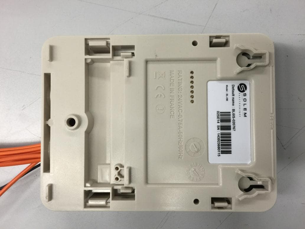
YWW-BLIS
Apr 28, 2015Irrigation Module Sector
Equipment Class
DSS - Part 15 Spread Spectrum Transmitter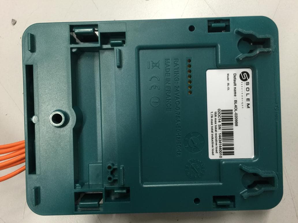
YWW-BLOL
Apr 07, 2015Automatic Devices
Equipment Class
DSS - Part 15 Spread Spectrum Transmitter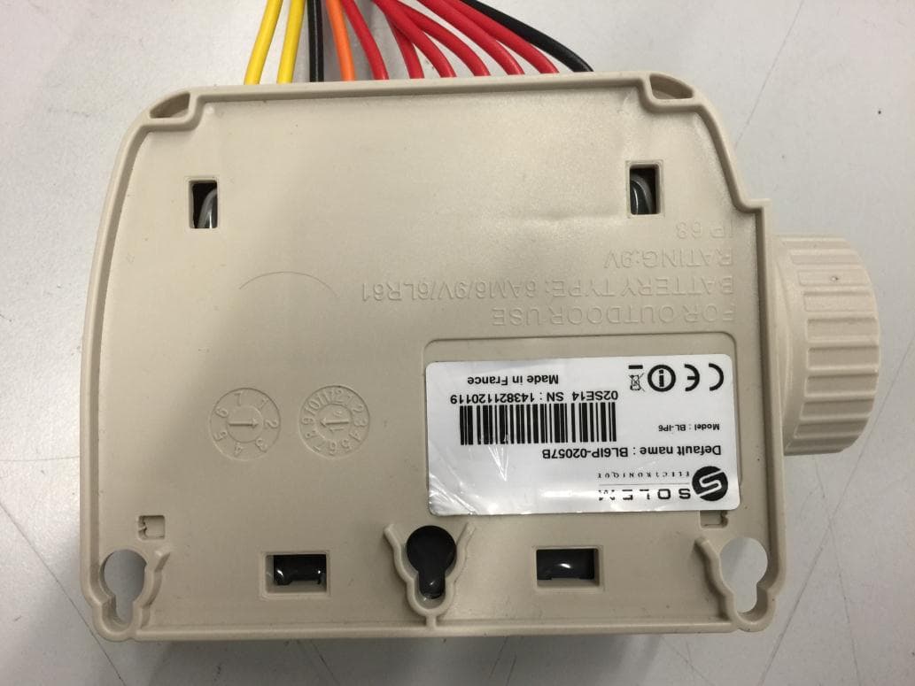
YWW-BLIP
Mar 29, 2015Irrigation Module Battery
Equipment Class
DSS - Part 15 Spread Spectrum Transmitter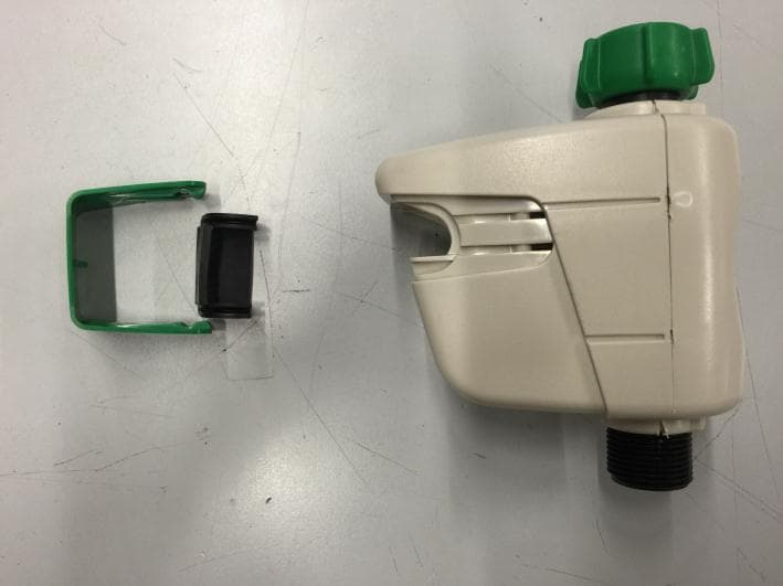
YWW-BLNR
Mar 29, 2015hose end controller
Equipment Class
DSS - Part 15 Spread Spectrum Transmitter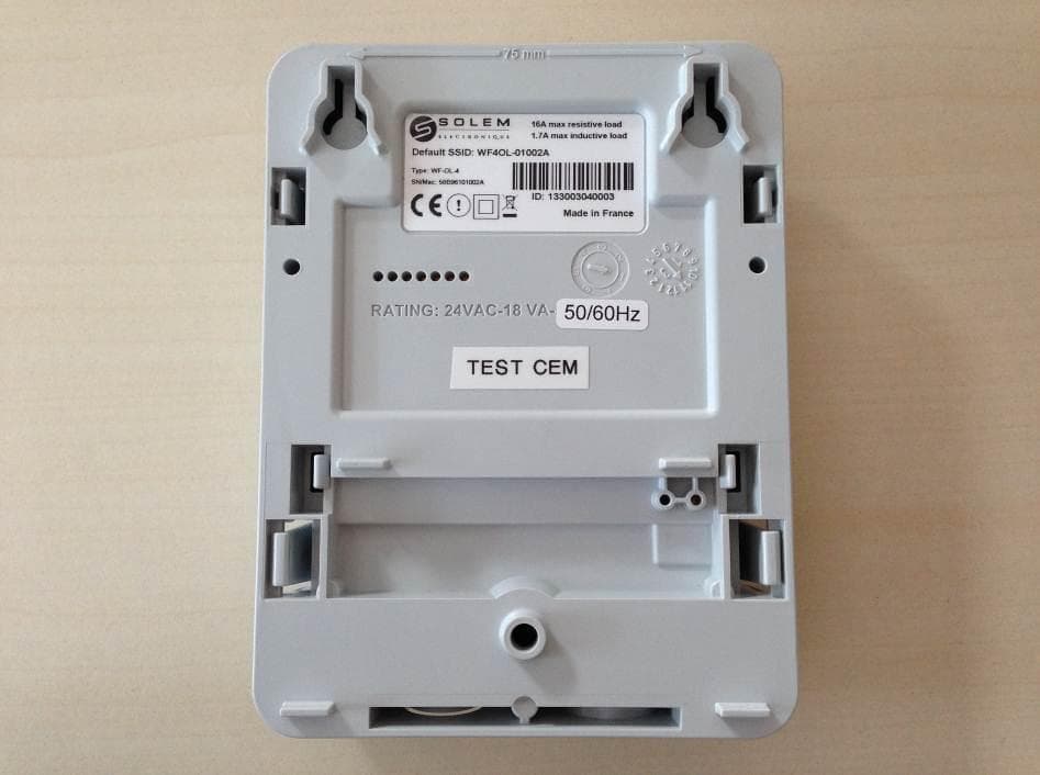
YWW-WFS
Mar 17, 2014Digital Device
Equipment Class
DTS - Digital Transmission System