ZZNPM301Power meter with BLE and ANT+ for bicycle
4iiii Innovations Inc.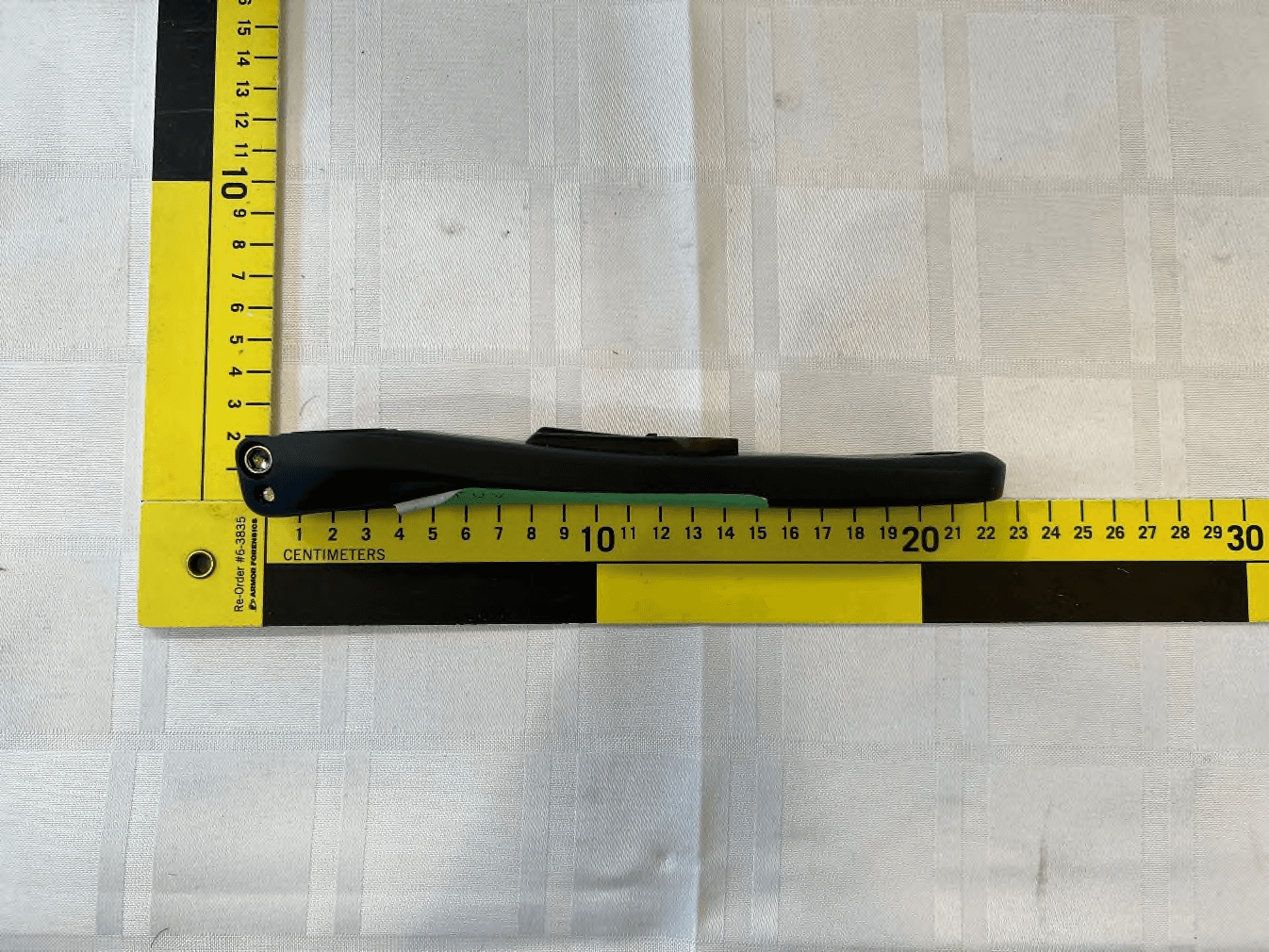
Click to zoom
Application Details
- Equipment Class
- DTS - Digital Transmission System
- Date of Grant
- Jun 05, 2023
- Application Purpose
- Original Equipment
- Date of Application
- Jun 05, 2023
- Equipment Note
- Power meter with BLE and ANT+ for bicycle
- Frequency Range
- 2402.00000000 - 2480.00000000
- Company
- 4iiii Innovations Inc.
- Country
- Canada
Documents & Files
Document Text
Text extracted from the exhibit documents filed with the FCC. Open a document above to read the original.
Users Manual
USER MANUAL PRECISION 3 POWERMETER VERSION 4 AUGUST 2023 CONTENTS 1 INTRO 1.1 YOUR PRECISION 3 POWERMETER [COMPONENT DIAGRAM] 1 1.2 INSTALLATION 1 1.3 GET READY TO RIDE [QUICK START] 2-3 2 PAIR PRECISION 3 PRO 2.1 PAIR WITH THE 4iiii APP 4 2.2 COMPATIBLE DISPLAY UNITS 5 2.3 PAIR WITH A DISPLAY UNIT OVER ANT+ 5 3 ZERO OFFSET 3.1 ZERO OFFSET USING YOUR DISPLAY UNIT 6 3.2 ZERO OFFSET USING THE 4iiii APP 7 3.3 ZERO OFFSET RESPONSE CODES 7 4 CONFIGURE 4.1 UPDATE FIRMWARE 8 4.2 POWER METER FACTORY RESET 9 4.3 ADVANCED FEATURES 9 5 APPLE FIND MY APP 5.1 SETTING UP YOUR POWER METER IN THE APPLE FIND MY APP 10-11 5.2 SERIAL NUMBER LOOK UP 12 5.3 DISABLING APPLE FIND MY 12 5.4 APPLE FIND MY FACTORY RESET 12 6 MAINTENANCE 6.1 CLEANING AND STORAGE 13 6.2 BATTERY LIFE AND BATTERY REPLACEMENTS 13 7 SPECIFICATIONS 14 8 TROUBLESHOOT 8.1 WHAT DO THE POWER METER LIGHTS MEAN? 15 8.2 TROUBLESHOOT BLUETOOTH AND ANT+ CONNECTIONS 15 9 WARRANTY 16 10 COMPLIANCE 17 11 WARNINGS 18 12 CONTACT 19 1. INTRO 1 Preinstalled CR2032 Battery 1.1Your PRECISION 3 POWERMETER Congratulations on your 4iiii PRECISION 3 Powermeter purchase complete with Apple Find My capabilities! PRECISION 3 Battery Cap LED Indicator Light 1.2 Installation Install your 4iiii power meter and crankset following the crankset manufacturer’s instructions. The steps to install the crankset vary between models. Follow the manufacturer’s instructions, or consult your local bike mechanic for assistance. Installation instructions for your new Shimano crankset are included with the Ride Ready option. 1. INTRO 2 2. Wake up PRECISION 3 by rotating the crank 3-4 times. 3. Pair your power meter with a compatible display unit using ANT+ or Bluetooth. Refer to Section 2.3 for full instructions. 1.3Get ready to ride (Quick Start) 1. Connect to the Apple Find My app (Android users skip this step) Refer to Section 5 for full instructions. (a) Remove and reinstalling the battery on your Non-Drive Side PRECISION 3 Powermeter three times (x3) to trigger Apple Find My pairing mode. (b) From the Apple Find My app, add your PRECISION 3 Powermeter. 1. INTRO 3 4. Perform a zero offset (some units refer to this as calibration). Refer to Section 3 for full instructions. (a) Unclip and dismount. Hold the bike upright and stationary, and position the crank arms at 12 and 6 o’clock, with the non-drive side crank arm down. (b) Select “Zero” or “Calibrate” on your display unit. ZERO-OFFSET CALIBRATE 12 6 NON-DRIVE SIDE DRIVE SIDE 2. PAIRING 4 Download the 4iiii app for iOS or Android to configure your power meter, update firmware and access advanced features. Search for “4iiii” on the Apple App Store or Google Play Store. Find the complete 4iiii App User Guide at 4iiii.com/docs 2.1Pair with the 4iiii app 1. Open the 4iiii app and log in. If this is your first time using the app, you will need to create an account. Once you have logged in the app will take you directly to the Devices tab. 2. Spin the crank 3-4 times to wake up your power meters. 3. Select Add a Device. 4. Select your power meter from the list of available devices. A check mark indicates the device is selected. 5. Press Connect. Tip: You can identify your power meter using the ANT+™ ID numbers etched onto the side of the pod. 2. PAIRING 5 2.2Compatible display units To view and record power and cadence data from your power meter, pair it with a compatible head unit or smart watch. Compatible devices pair with your power meter using one of the following protocols: • Bluetooth • ANT+ Consult the head unit or watch manufacturer for compatibility and pairing instructions. 2.3Pair with a display unit over ANT+ Pairing steps vary between display units. Consult your display unit’s user manual for specific instructions. The following are generic instructions for ANT+ enabled display units: 1. Turn on your display unit. 2. Spin the crank 3-4 times to wake up your power meter. 3. Navigate to the “sensors” menu on your display unit. 4. Add a new sensor. 5. Select only your power meter ANT+ ID from the list of available devices and connect. Tip:Your power meter’s ANT+ ID is etched on the side of pod. Once paired, most display units will remember your power meter and automatically connect when both devices are on. POWER METER METRICS Additional power metrics can be added to your display unit’s workout screen. Consult the display unit’s user manual for instructions. Fields that are available on many display units include: •Power (1 sec. 3 sec. 10 sec.) •Normalized Power •Intensity Factor •TSS (training stress scores) •Power Balance (dual power meters only) •Cadence 3. ZERO OFFSET 6 3.1Zero Offset using your display unit. Zero offset (calibrate) your power meter using your display unit before riding. For optimal performance, allow the power meters to adjust to the ambient riding temperature before performing a zero offset. This normally takes just a few minutes. 1. Unclip and dismount from your bike for the zero offset. 2. Spin the crank arms 3-4 times to wake your power meter. 3. Connect your power meter with your display unit. 4. Place your crank arms at 12 and 6 o’clock, with the non-drive side crank arm down. Hold the bike stable and upright. 5. Use your display unit to calibrate your power meter. A. Navigate to the Zeroing or Calibration menu. B. Press “Zero” or “Calibrate”. Tip: If you receive an error message, check that the bike is stable and upright and the cranks are in the correct position before trying again. 12 O’CLOCK DRIVE SIDE 6 O’CLOCK NON-DRIVE SIDE 3. ZERO OFFSET 7 3.2Zero offset using the 4iiii app 1. Unclip and dismount from your bike for the zero offset. 2. Spin the crank arms 3-4 times to wake your power meters. 3. From the Devices tab, click the Zero Offset icon below your power meter’s name. 4. Place your crank arms in the 12 and 6 o’clock positions, with the non-drive side crank arm downwards. Make sure the bike is stable and upright. Then tap on the crank arm image. TWO DIGIT RESPONSE RESULT DESCRIPTIO…
Text truncated - open the document above for the full version.
Attestation Statements
Date: 4/26/2023 To: Federal Communications Commission Authorization and Evaluation Division 7435 Oakland Mills Road Columbia, MD 21046 USA Ref: Attestation Statements Part 2.911(d)(5)(i) and Part 2.911(d)(5)(ii) Filing Re. KDB 986446 D01 FCC ID: ZZNPM301 Dear Sir or Madam, 4iiii Innovations Inc. (“the applicant”) certifies that the equipment for which authorization is sought is not “covered” equipment prohibited from receiving an equipment authorization pursuant to section 2.903 of the FCC rules. We also certify that, as of the date of the filing of the application, the applicant is not identified on the Covered List as an entity producing “covered” equipment. If you have any questions, please contact us. Sincerely, Contact name: Michael Mercer Company name: 4iiii Innovations Inc. Address: 141 2 nd Ave E, Cochrane, Alberta, T4C 2B9, Canada E-mail: [email protected] Tel: 1-403-800-3095
Attestation Statements
4iiii InnovationsInc. 141 2Ave E Cochrane,AB T4C 2B9 Canada To: Fede ral CommunicationsCommission Authoriz ationandEvaluationDiv ision 7435 Oak landMills Road Columbia,MD 21046 USA Da te: 05-0 3-2 023 Ref: AttestationSt atements Par t 2.9 11(d)(7) Filing FCC ID: (ZZNPM301) 4iiii InnovationsInc . (“theapplican t”) ce rtifie s tha t, as of the da te of the filingof the application, Cor por ationSe rvice Compan y, 251 Lit tle Falls Dr iv e, Wilm ing ton, DE 19808 is our de sig na ted ag ent to receiv e se rvice of pr oc ess in the U.S. for the abo ve reference d FCC ID . 4iiii InnovationsInc . ag rees to main tain an ag ent to receiv e se rvice of pr oc ess in the U.S. for no le ss thanoneyear aft er the gran tee has termina ted all mar ketingandim por tationor the conc lusionof an y Commission-rela ted pr oc eeding in volv ing the equipment. Sinc erely , 4iiii InnovationsInc . By: ___________________________ Nam e: Jim Glasspoole Title: CF O Cor por ationSe rvice Compan y ac cepts, as of the da te of the filingof the application,appointm ent as ag ent to receiv e se rvice of pr oc ess for 4iiii InnovationsInc . De sig na ted U.S. Agent In for mation: Nam e: Cor por ationSe rvice Compan y Addr ess: 251 Lit tle Falls Dr iv e, Wilm ing ton, DE 19808 Con tac t Person:Litig ationManagement Se rvice s Tel.: (3 02) 636-5 400 Em ail: SOP @cscg lobal.com FRN : Not applicable Cor por ationSe rvice Compan y By: ______________________________ Nam e: Title: Rev1/26/2023 Sylvia M. Buxbaum Authorized Representative Rev1/26/2023
Attestation Statements
Corporation Service Company ZZNPM301
Cover Letter(s)
Date: 4/26/2023 TUV SUD America Inc. 10 Centennial Drive Peabody, MA 01960, USA Dear Sir or Madam, We, 4iiii Innovations Inc. at 141 2 nd Ave E, Cochrane, Alberta, T4C 2B9, Canada, hereby authorize of Jadon Bull of TUV SUD Canada Inc, 11 Gordon Collins, Gormley, L0H 1G0, Canada; 905-883-7255 to act as our agent in all matters relating to applications for equipment authorization, including the signing of all documents relating to these matters. The authorization expires on April 26 th , 2024. Yours sincerely, Name: Michael Mercer Title: Director of Engineering
Cover Letter(s)
Date: 4/26/2023 Federal Communications Commission Equipment Authorization Branch 7435 Oakland Mills Road Columbia, MD 21046 Confidentiality Request FCC ID: ZZNPM301 Pursuant to Sections 0.457(d)(1)(ii) and 0.459 of the Commission’s Rules, 4iiii Innovations Inc. hereby requests permanent confidential treatment of information accompanying this application as outlined below: Schematics Bill of Materials/Parts List Block Diagrams Theory of Operation The above materials contain trade secrets and proprietary information not customarily released to the public. The public disclosure of these matters might be harmful to the Applicant and provide unjustified benefits to its competitors. The Applicant understands that pursuant to Rule 0.457(d)(1)(ii), disclosure of this Application and all accompanying materials will not be made before the date of the Grant for this Application. Yours sincerely, Name: Michael Mercer Company: 4iiii Innovations Inc.
Cover Letter(s)
Radientum Oy | Visiokatu 4 | 33720 Tampere, Finland | +358 40 501 3535 | [email protected] | www.radientum.com INTEGRATED ANTENNA DATASHEET 1. Features RAD-2834 is a custom designed sheet metal antenna intended for Bluetooth applications. Antenna is assembled in to a printed circuit board (PCB) of the product where it is used. Integrated antenna is product specific and this specification is valid only when antenna is installed into the product it is designed for. Antenna uses an impedance matching circuit integrated to the host device PCB. Figure 1 Picture of the antenna 2. General Data Part Number RAD-2834 Frequency 2400MHz-2487MHz Operating temperature -30 o C to +80 o C Nominal Impedance 50Ω with impedance matching circuit Connection type Solder to PCB Max Power handling 1W Radientum Oy | Visiokatu 4 | 33720 Tampere, Finland | +358 40 501 3535 | [email protected] | www.radientum.com 3. RF Characteristics Figure 2. RAD.2834 Antenna radiation pattern at 2440MHz. Measurement has been conducted using the transmitter of the product with power set to 0 dBm Antenna RAD-2834 Frequency Range 2400MHz-2487MHz Max Peak Gain -7dBi Return loss 6 dB typical Radientum Oy | Visiokatu 4 | 33720 Tampere, Finland | +358 40 501 3535 | [email protected] | www.radientum.com Figure 3 RAD-2834 Antenna S11 measured when assembled at product. 4. Mechanical dimensions 5. Conformity Antenna is in compliance with the essential requirements and other relevant provisions of Directive 2011/65/EU (RoHS)
External Photos
Report File #: 7169012749-000 – External Photos © TÜV SÜD Canada Inc. This test report shall not be reproduced except in full, without written approval of TÜV SÜD Canada Inc. Exhibit: External Photos FCC ID: ZZNPM301 IC: 9896A-PM300 Client 4iiii Innovations Inc. Product Precision 3 Powermeter – PML300 Standard(s) RSS 247 Issue 2:2017 FCC Part 15 Subpart 15.247 Page 2 of 6 Report Issued: 5/3/2023 Report File #: 7169012749-000 – External Photos © TÜV SÜD Canada Inc. This test report shall not be reproduced except in full, without written approval of TÜV SÜD Canada Inc. Figure 1 – EUT External Photo Front – PML300 Client 4iiii Innovations Inc. Product Precision 3 Powermeter – PML300 Standard(s) RSS 247 Issue 2:2017 FCC Part 15 Subpart 15.247 Page 3 of 6 Report Issued: 5/3/2023 Report File #: 7169012749-000 – External Photos © TÜV SÜD Canada Inc. This test report shall not be reproduced except in full, without written approval of TÜV SÜD Canada Inc. Figure 1 – EUT External Photo Side – PML300 Client 4iiii Innovations Inc. Product Precision 3 Powermeter – PML300 Standard(s) RSS 247 Issue 2:2017 FCC Part 15 Subpart 15.247 Page 4 of 6 Report Issued: 5/3/2023 Report File #: 7169012749-000 – External Photos © TÜV SÜD Canada Inc. This test report shall not be reproduced except in full, without written approval of TÜV SÜD Canada Inc. Figure 2 – EUT External Photo Back – PML300 Client 4iiii Innovations Inc. Product Precision 3 Powermeter – PML300 Standard(s) RSS 247 Issue 2:2017 FCC Part 15 Subpart 15.247 Page 5 of 6 Report Issued: 5/3/2023 Report File #: 7169012749-000 – External Photos © TÜV SÜD Canada Inc. This test report shall not be reproduced except in full, without written approval of TÜV SÜD Canada Inc. Figure 3 – EUT External Photo Front – PMR300 Client 4iiii Innovations Inc. Product Precision 3 Powermeter – PML300 Standard(s) RSS 247 Issue 2:2017 FCC Part 15 Subpart 15.247 Page 6 of 6 Report Issued: 5/3/2023 Report File #: 7169012749-000 – External Photos © TÜV SÜD Canada Inc. This test report shall not be reproduced except in full, without written approval of TÜV SÜD Canada Inc. Figure 4 – EUT External Photo Back – PMR300
ID Label/Location Info
Report File #: 7169012749-000 - Labels © TÜV SÜD Canada Inc. This test report shall not be reproduced except in full, without written approval of TÜV SÜD Canada Inc. Exhibit: Sample Label & Location FCC ID: ZZNPM301 IC: 9896A-PM300 Client 4iiii Innovations Inc. Product Precision 3 Powermeter – PML300 & PMR300 Standard(s) RSS 247 Issue 2:2017 FCC Part 15 Subpart 15.247 Page 2 of 3 Report Issued: 5/3/2023 Report File #: 7169012749-000 - Labels © TÜV SÜD Canada Inc. This test report shall not be reproduced except in full, without written approval of TÜV SÜD Canada Inc. Figure 1 – Sample Label – PML300 Client 4iiii Innovations Inc. Product Precision 3 Powermeter – PML300 & PMR300 Standard(s) RSS 247 Issue 2:2017 FCC Part 15 Subpart 15.247 Page 3 of 3 Report Issued: 5/3/2023 Report File #: 7169012749-000 - Labels © TÜV SÜD Canada Inc. This test report shall not be reproduced except in full, without written approval of TÜV SÜD Canada Inc. Figure 2- Sample Label – PMR300
Internal Photos
Report File #: 7169012749-000 – Internal Photos © TÜV SÜD Canada Inc. This test report shall not be reproduced except in full, without written approval of TÜV SÜD Canada Inc. Exhibit: Internal Photos FCC ID: ZZNPM301 IC: 9896A-PM300 Client 4iiii Innovations Inc. Product Precision 3 Powermeter – PML300 Standard(s) RSS 247 Issue 2:2017 FCC Part 15 Subpart 15.247 Page 2 of 3 Report Issued: 5/3/2023 Report File #: 7169012749-000 – Internal Photos © TÜV SÜD Canada Inc. This test report shall not be reproduced except in full, without written approval of TÜV SÜD Canada Inc. Figure 1 – EUT Internal Photo Front Client 4iiii Innovations Inc. Product Precision 3 Powermeter – PML300 Standard(s) RSS 247 Issue 2:2017 FCC Part 15 Subpart 15.247 Page 3 of 3 Report Issued: 5/3/2023 Report File #: 7169012749-000 – Internal Photos © TÜV SÜD Canada Inc. This test report shall not be reproduced except in full, without written approval of TÜV SÜD Canada Inc. Antenna Figure 2 – EUT Internal Photo Back
RF Exposure Info
Report File #: 716901274-000 - RF Exposure © TÜV SÜD Canada Inc. This test report shall not be reproduced except in full, without written approval of TÜV SÜD Canada Inc. Exhibit: RF Exposure – FCC FCC ID: ZZNPM301 Client 4iiii Innovations Inc. Product Precision 3 Powermeter – PML300 & PMR300 Standard(s) FCC KDB 447498 v07 Page 2 of 7 Report Issued: 5/3/2023 Report File #: 716901274-000 - RF Exposure © TÜV SÜD Canada Inc. This test report shall not be reproduced except in full, without written approval of TÜV SÜD Canada Inc. RF Exposure Calculation (FCC) Purpose The purpose of this test is to ensure that the RF energy transmitted at a specified operating distance from the human body meets the criteria to be exempt from routine evaluation. The RF Exposure values are calculated based upon measurements obtained during testing and are compared to the applicable exposure limits for individual RF sources. If multiple RF sources are used within a host product, and they operate simultaneously, an additional exemption criterion based on total exposure from multiple RF sources is also applied. If the exemption criteria are not met, the RF sources may be required to undergo routine evaluation for RF Exposure. Limit(s) and Method The test method and exemption limits are defined in FCC KDB 447498 and FCC 1.1307(b)(3) and are applicable to both unintentional and intentional RF sources, whether portable, mobile, or fixed installations. Individual RF Sources For individual sources, the following three exemption criteria options are defined. Any of the three options may be used to determine the RF source to be exempt from routine evaluation if it meets the corresponding exemption limit. Defined in FCC 1.1307(b)(3)(i)(A), Exemption Criteria Option A is based on the maximum time-averaged output power. The requirement is that this measurement must not exceed 1mW, regardless of separation distance, and in the frequency range of 100kHz-100GHz. Client 4iiii Innovations Inc. Product Precision 3 Powermeter – PML300 & PMR300 Standard(s) FCC KDB 447498 v07 Page 3 of 7 Report Issued: 5/3/2023 Report File #: 716901274-000 - RF Exposure © TÜV SÜD Canada Inc. This test report shall not be reproduced except in full, without written approval of TÜV SÜD Canada Inc. Defined in FCC 1.1307(b)(3)(i)(B), Exemption Criteria Option B is based on SAR using the measurement of maximum time-averaged output power or ERP, whichever is greater. This option is applicable to separation distances of 0.5cm-40cm and in the frequency range of 300MHz-6GHz. The limit is defined below: Defined in FCC 1.1307(b)(3)(i)(C), Exemption Criteria Option C is based on MPE using the ERP measurement. This option is only applicable for separation distances greater than or equal to the wavelength of the frequency under consideration divided by 2π, and in the frequency range of 300kHz-100GHz. The limit is defined below: Client 4iiii Innovations Inc. Product Precision 3 Powermeter – PML300 & PMR300 Standard(s) FCC KDB 447498 v07 Page 4 of 7 Report Issued: 5/3/2023 Report File #: 716901274-000 - RF Exposure © TÜV SÜD Canada Inc. This test report shall not be reproduced except in full, without written approval of TÜV SÜD Canada Inc. Multiple RF Sources For multiple sources, the following two exemption criteria options are defined. Exemption criteria for multiple RF sources is applicable if the EUT contains any RF sources that may operate simultaneously. Defined in FCC 1.1307(b)(3)(ii)(A), the results of only the exemption criteria option A calculation for for each individual RF source shall be used to determine exemption for multiple RF sources. The criteria for exemption are defined below: 1.If the separation distance between each individual RF source is at least 2 centimeters, and each individual source meets exemption criteria option A for single RF sources. 2.If the sum of maximum output power of multiple RF sources is less than 1mW, the sources can be treated as a single source and are exempt based on exemption criteria option A for single RF sources. Defined in FCC 1.1307(b)(3)(ii)(B), the exemption ratios calculated for each individual RF source shall be used to calculate the Total Exposure Ratio. This calculation includes exemption criteria calculated using Exemption Criteria Options B or C, or the measurement results of any RF source that may have been subject to routine evaluation. The limit is defined below: Client 4iiii Innovations Inc. Product Precision 3 Powermeter – PML300 & PMR300 Standard(s) FCC KDB 447498 v07 Page 5 of 7 Report Issued: 5/3/2023 Report File #: 716901274-000 - RF Exposure © TÜV SÜD Canada Inc. This test report shall not be reproduced except in full, without written approval of TÜV SÜD Canada Inc. Results The EUT is exempt from routine evaluation of RF exposure based on the following calculations: Single RF Source 1 Analysis – 2.4GHz BLE Transmitter The 2400MHz BLE Transmitter has maximum output power at the low channel frequency of 2402MHz. The values related to the PML300 model are used as a worst-case representative of both the PML300 and PMR300. The separation distance is taken as 5mm for a worst-case scenario. Frequency (MHz): 2402 Separation Distance (cm): 0.5 Antenna Gain (dBi): -7 Conducted Power (dBm): 4.15 Conducted Power (mW): 2.60 ERP (mW): 0.52 Exemption Criteria Option A: Threshold Power = 1mW 2.60mW > 1mW Option A is not applicable. Exemption Criteria Option B: Threshold Power = 2.79mW 2.60mW < 2.79mW Option B is applicable. Contribution Ratio = 2.60/2.79 = 0.933 Exemption Criteria Option C: λ/2π = 0.02m R = 0.005m 0.005m < 0.02m Option C is not applicable. Therefore, the RF source is exempt from routine evaluation based on Exemption Criteria Option B with contribution ratio of 0.933. Client 4iiii Innovations Inc. Product Precision 3 Powermeter – PML300 & PMR300 Standard(s) FCC KDB 447498 v07 Page 6 of 7 Report Issued: 5/3/2023 Report File #: 716901274-000 - RF Exposure © TÜV SÜD Canada Inc. This test report shall …
Text truncated - open the document above for the full version.
Test Report
Registration # 6844A-3 Testing Laboratory Certificate #2955.02 R-14023, G-20072 C-14498, T-20060 Registration # CA6844 Page 1 of 93 Report Issued: 5/24/2023 Report File #: 7169012749RF-BLE-000 © TÜV SÜD Canada Inc. This test report shall not be reproduced except in full, without written approval of TÜV SÜD Canada Inc. FCC 15 247 Rev3 RF Test Report As per RSS-247 Issue 2:2017 & FCC Part 15 Subpart 15.247 Unlicensed Intentional Radiators on the Precision 3 Powermeter PML300 and PMR300 (BLE Transmitter) Issued by: TÜV SÜD Canada Inc. 11 Gordon Collins Dr, Gormley, ON, L0H 1G0 Canada Ph: (905) 883-7255 Testing produced for See Appendix A for full client & EUT details. Prepared by: Jadon Bull, Project Engineer Reviewed by: Min Xie, Sr. Project Engineer Client 4iiii Innovations Product PML300 and PMR300 Standard(s) RSS 247 Issue 2:2017 FCC Part 15 Subpart 15.247 Page 2 of 93 Report Issued: 5/24/2023 Report File #: 7169012749RF-BLE-000 © TÜV SÜD Canada Inc. This test report shall not be reproduced except in full, without written approval of TÜV SÜD Canada Inc. Table of Contents Table of Contents ................................................................................................................... 2 Report Scope .......................................................................................................................... 3 Summary ................................................................................................................................ 4 Test Results Summary ....................................................................................................... 5 Notes, Justifications, or Deviations ................................................................................... 6 Sample Calculation(s) ........................................................................................................ 6 Applicable Standards, Specifications and Methods ............................................................... 7 Document Revision Status ..................................................................................................... 8 Definitions and Acronyms ..................................................................................................... 9 Testing Facility .................................................................................................................... 10 Calibrations and Accreditations ....................................................................................... 10 Testing Environmental Conditions and Dates ................................................................. 11 Detailed Test Results Section .............................................................................................. 12 6dB Bandwidth of Digitally Modulated Systems ............................................................ 13 Maximum Peak Envelope Conducted Power .................................................................. 21 Antenna Spurious Conducted Emissions (-20 dBc Requirement) ................................... 30 Transmitter Spurious Radiated Emissions ....................................................................... 40 Power Spectral Density .................................................................................................... 86 Appendix A – EUT Summary .............................................................................................. 91 Appendix B – EUT and Test Setup Photos .......................................................................... 93 Client 4iiii Innovations Product PML300 and PMR300 Standard(s) RSS 247 Issue 2:2017 FCC Part 15 Subpart 15.247 Page 3 of 93 Report Issued: 5/24/2023 Report File #: 7169012749RF-BLE-000 © TÜV SÜD Canada Inc. This test report shall not be reproduced except in full, without written approval of TÜV SÜD Canada Inc. Report Scope This report addresses the EMC verification testing and test results of the Precision 3 Powermeter Models: PML300 and PMR300, and are herein referred to as EUT (Equipment Under Test). The EUT was tested for compliance against the following standards: RSS-247 Issue 2:2017 FCC Part 15 Subpart C 15.247 Test procedures, results, justifications, and engineering considerations, if any, follow later in this report. This report does not imply product endorsement by any government, accreditation agency, or TÜV SÜD Canada Inc. Opinions or interpretations expressed in this report, if any, are outside the scope of TÜV SÜD Canada Inc. accreditations. Any opinions expressed do not necessarily reflect the opinions of TÜV SÜD Canada Inc., unless otherwise stated. Client 4iiii Innovations Product PML300 and PMR300 Standard(s) RSS 247 Issue 2:2017 FCC Part 15 Subpart 15.247 Page 4 of 93 Report Issued: 5/24/2023 Report File #: 7169012749RF-BLE-000 © TÜV SÜD Canada Inc. This test report shall not be reproduced except in full, without written approval of TÜV SÜD Canada Inc. Summary The results contained in this report relate only to the item(s) tested. EUT: Precision 3 Powermeter PML300 & PMR300 FCC Certification #, FCC ID: ZZNPM301 ISED Certification #, IC: 9896A-PM300 EUT passed all tests performed Yes Tests conducted by Jadon Bull Report reviewed by Min Xie For testing dates, see "Testing Environmental Conditions and Dates". Client 4iiii Innovations Product PML300 and PMR300 Standard(s) RSS 247 Issue 2:2017 FCC Part 15 Subpart 15.247 Page 5 of 93 Report Issued: 5/24/2023 Report File #: 7169012749RF-BLE-000 © TÜV SÜD Canada Inc. This test report shall not be reproduced except in full, without written approval of TÜV SÜD Canada Inc. Test Results Summary Standard/Method Description Class/Limit Result FCC 15.203 Antenna Requirement Unique Pass See Justification FCC 15.205 RSS-GEN (Table 6) Restricted Bands for Intentional Operation QuasiPeak Average Pass FCC 15.207 RSS-GEN (Table 3) Power Line Conducted Emissions QuasiPeak Average N/A See Justification FCC 15.209 RSS-GEN (Table 4) Spurious Radiated Emissions Q…
Text truncated - open the document above for the full version.
Test Setup Photos
Report File #: 7169012749-000 – Test Setups © TÜV SÜD Canada Inc. This test report shall not be reproduced except in full, without written approval of TÜV SÜD Canada Inc. Exhibit: Test Setup Photos FCC ID: ZZNPM301 IC: 9896A-PM300 Client 4iiii Innovations Inc. Product Precision 3 Powermeter – PML300 & PMR300 Standard(s) RSS 247 Issue 2:2017 FCC Part 15 Subpart 15.247 Page 2 of 17 Report Issued: 5/3/2023 Report File #: 7169012749-000 – Test Setups © TÜV SÜD Canada Inc. This test report shall not be reproduced except in full, without written approval of TÜV SÜD Canada Inc. PML300 Figure 1 ‒ Radiated Emissions Setup (X-Axis – Worst Case) Client 4iiii Innovations Inc. Product Precision 3 Powermeter – PML300 & PMR300 Standard(s) RSS 247 Issue 2:2017 FCC Part 15 Subpart 15.247 Page 3 of 17 Report Issued: 5/3/2023 Report File #: 7169012749-000 – Test Setups © TÜV SÜD Canada Inc. This test report shall not be reproduced except in full, without written approval of TÜV SÜD Canada Inc. Figure 2 ‒ Radiated Emissions Setup 9kHz – 30MHz Client 4iiii Innovations Inc. Product Precision 3 Powermeter – PML300 & PMR300 Standard(s) RSS 247 Issue 2:2017 FCC Part 15 Subpart 15.247 Page 4 of 17 Report Issued: 5/3/2023 Report File #: 7169012749-000 – Test Setups © TÜV SÜD Canada Inc. This test report shall not be reproduced except in full, without written approval of TÜV SÜD Canada Inc. Figure 3 ‒ Radiated Emissions Setup 30MHz – 1GHz Note: As per ANSI C63.10-2013 Clause 6.3.1, below 1GHz, the height of the EUT was set to 80cm. Above 1GHz, the height was raised to 1.5m. Client 4iiii Innovations Inc. Product Precision 3 Powermeter – PML300 & PMR300 Standard(s) RSS 247 Issue 2:2017 FCC Part 15 Subpart 15.247 Page 5 of 17 Report Issued: 5/3/2023 Report File #: 7169012749-000 – Test Setups © TÜV SÜD Canada Inc. This test report shall not be reproduced except in full, without written approval of TÜV SÜD Canada Inc. Figure 4 ‒ Radiated Emissions Setup 1GHz – 6GHz Note: As per ANSI C63.10-2013 Clause 6.3.1, above 1GHz, the height of the EUT was set to 1.5m. Client 4iiii Innovations Inc. Product Precision 3 Powermeter – PML300 & PMR300 Standard(s) RSS 247 Issue 2:2017 FCC Part 15 Subpart 15.247 Page 6 of 17 Report Issued: 5/3/2023 Report File #: 7169012749-000 – Test Setups © TÜV SÜD Canada Inc. This test report shall not be reproduced except in full, without written appro…
Text truncated - open the document above for the full version.
Contact Information
Applicant
Michael Mercer(Director of Engineering)
Test Firm
TUV SUD CANADA (Gormley)William (Mac) Elliott
[email protected]813-284-2736
Technical Specifications
| # | Rule Parts | Frequency Range | Power Output |
|---|---|---|---|
| 1 | 15C | 2.40 GHz - 2.48 GHz | 26.00 mW |
Other Applications from 4iiii Innovations Inc.
ZZN-ST100
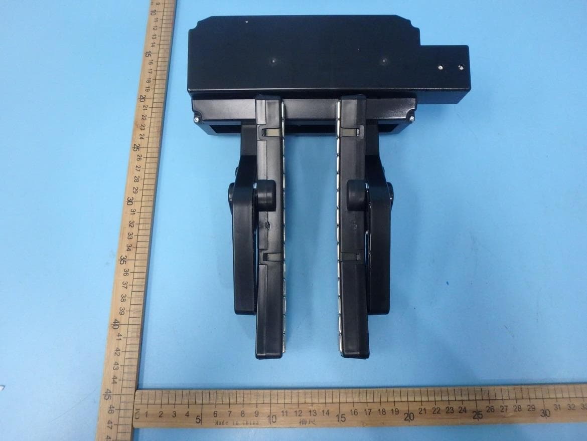
Mar 09, 2020Smart bicycle trainer
Equipment Class
DTS - Digital Transmission System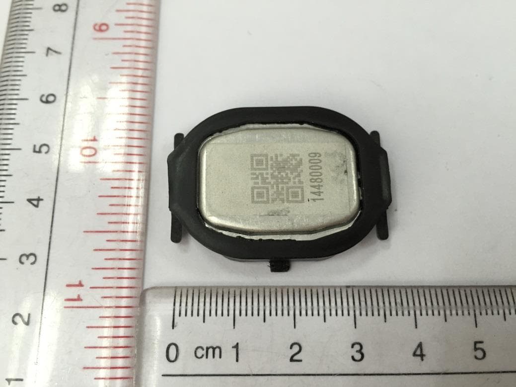
ZZNPM100
May 08, 2015Precision
Equipment Class
DXX - Part 15 Low Power Communication Device Transmitter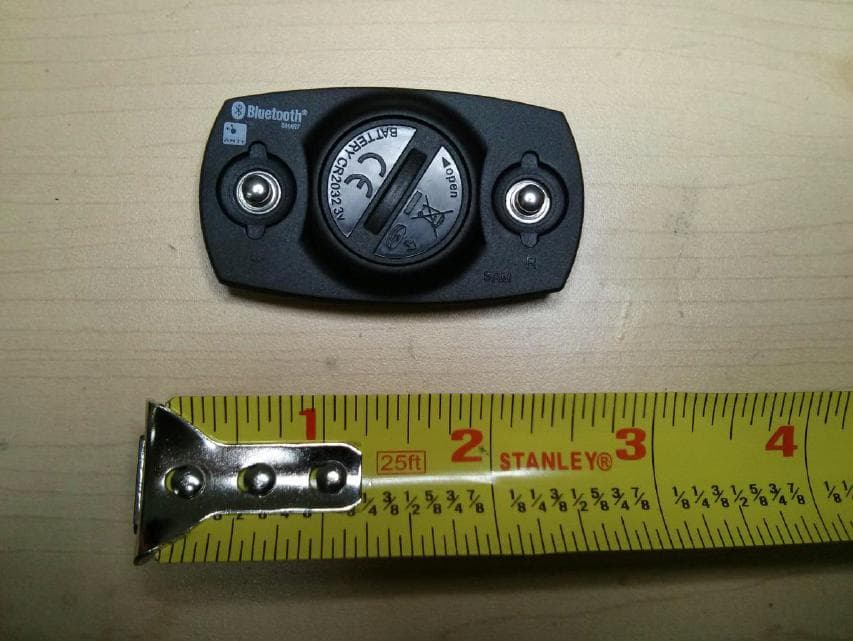
ZZNV100
Feb 10, 2013ZZNV100 ATHLETIC HEART RATE MONITOR ANT AND BTLE
Equipment Class
DXX - Part 15 Low Power Communication Device Transmitter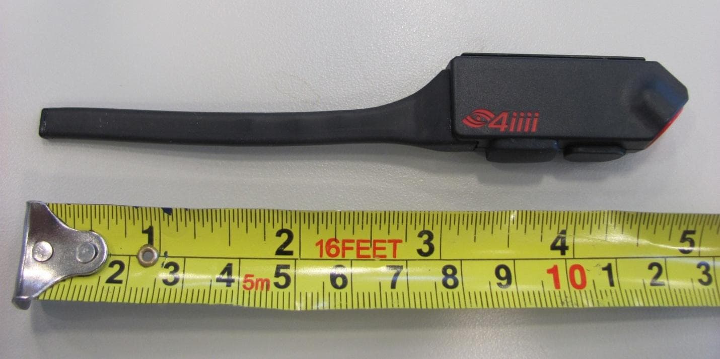
ZZNSP200
Dec 23, 2012ATHLETIC PARAMETER LED DISPLAY
Equipment Class
DXX - Part 15 Low Power Communication Device Transmitter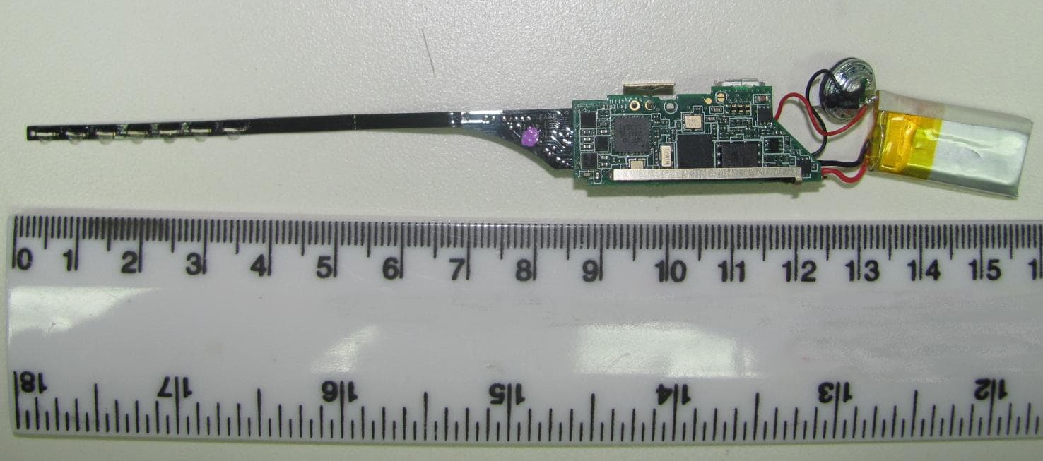
ZZNSP100
Nov 06, 2011ATHLETIC PARAMETER LED DISPLAY
Equipment Class
DXX - Part 15 Low Power Communication Device Transmitter