ZZNSP100ATHLETIC PARAMETER LED DISPLAY
4iiii Innovations Inc.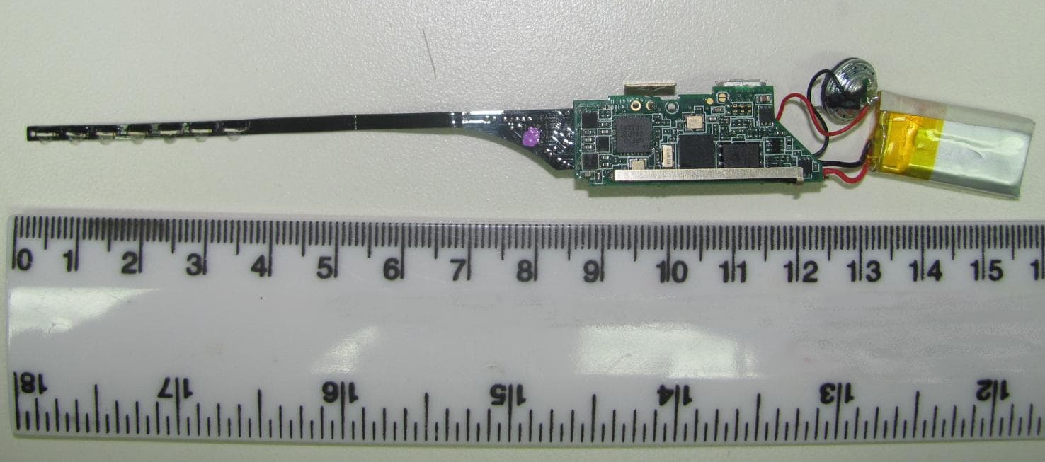
Click to zoom
Application Details
- Equipment Class
- DXX - Part 15 Low Power Communication Device Transmitter
- Date of Grant
- Nov 06, 2011
- Application Purpose
- Original Equipment
- Date of Application
- Nov 06, 2011
- Equipment Note
- ATHLETIC PARAMETER LED DISPLAY
- Frequency Range
- 2403.00000000 - 2480.00000000
- Company
- 4iiii Innovations Inc.
- Country
- Canada
Documents & Files
Document Text
Text extracted from the exhibit documents filed with the FCC. Open a document above to read the original.
Users Manual
Welcome to Sport-iiiis! Thank you for purchasing Sport-iiiis. Sport-iiiis is a heads-up display – it gives you the data you need to stay in your target range (zone) in any of several measures (including heart rate, cadence, power, and pace/speed) while running or cycling, without you having to look down at a watch, cyclocomputer, etc. It can pair with, and receive this data from, any ANT+-enabled heart rate strap, foot pod, power, or speed/cadence sensor. When properly mounted to your glasses, the boom of the Sport-iiiis unit will be in your peripheral vision, so that its LEDs can tell you whether you are below, above, or in your zone by their color (green, yellow, orange, or red) and position. Through the downloadable Sport-iiiis software interface for your Windows or Mac OS computer, you can set up the Sport-iiiis unit and configure the zones for your individual needs. What’s in the Box? Sport-iiiis Unit (2) Mounting Brackets Tie Wraps USB Charge/Sync Cable Getting to Know Your Sport-iiiis Unit Speaker gives audio prompts either when triggered by Tip- Tap or (optionally) when above or below zone for currently enabled sensor Micro-USB Port connect to computer to configure, charge, and sync your Sport-iiiis unit Power Button capacitive-touch button (merely has to be touched, cannot be depressed), powers Sport-iiiis on and off and controls other functions Boom contains seven LEDs (Light-Emitting Diodes) that can be programmed by color and position to indicate where your per- formance is relative to the target zone for your cur- rently-enabled sensor ACTIONSPORT-IIIIS POWERED ONSPORT-IIIIS POWERED OFF press Power Button (unit beeps once) hold Power Button until unit beeps twice hold Power Button until unit beeps three times hold Power Button until unit beeps four times start/stop sessionshow remaining battery power turns Sport-iiiis unit offturns Sport-iiiis unit on switch bike/run mode -------------- pair sensors clear all paired sensors & pair Functions of the Power Button T i p Ta p Your Sport-iiiis unit contains an accelerometer, which allows it to respond to single and double “taps,” as seen below: While it is powered on, a single tap will cause your Sport-iiiis unit to ennuciate the measurement from the active sen- sor, and a double tap (two taps in rapid succession) will switch between currently paired sensors. Download and Set Up the Sport-iiiis Software Both Windows and Mac OS versions of the Sport-iiiis Application are available for download at: http://www.4iiii.com/support.html Windows Software Installation: 1. Download the Sport-iiiis Application Installer from http:// www.4iiii.com/support.html 2. Double-click on “installSport-iiiis.exe” to activate the Installer. 3. Click on “Close” in the Installer’s dialog box once installation is complete. 4. Double-click on the “Sport-iiiis” shortcut on your desktop to open the Sport-iiiis Application. Mac OS Software Installation: 1. Download the Sport-iiiis Application from http://www.4iiii. com/support.html 2. Drag Sport-iiiis Application to your “Applications” folder. 3. In your “Applications” folder, find the “Sport-iiiis” icon and double-click on it to open the Sport-iiiis application Create Your Profile Enter your name, email, height, weight, birth year, gender, unit of measurement (English or Metric), and desired run display (pace or speed) to set up the initial configuration. You may always update this later by clicking on the “Profile” tab and making any desired changes. Set Your Target Zones In addition to the optional ANT+ heart rate strap, your Sport-iiiis unit is compatible with any ANT+- enabled bike (power, speed & cadence) and run (foot pod) sensors. You can choose target zones for the data provided by each of these sensors by clicking on the “Zones” tab in the left column of the Sport-iiiis software interface and then choosing the appropriate activity type (“Run” or “Bike”) in the upper right of the interface window. Then, on the bottom of the interface window, choose the sensor for which you would like to adjust the zone setup (Heartrate, Pace, and Cadence for Run, or Heart- rate, Speed, Cadence, and Power for Bike). The diamond in each zone indicates the LED color for that zone, and it can be moved up and down to adjust the LED color for that zone. To adjust the boundaries for each zone, simply click on the boundary you would like to adjust and drag your mouse in the appropriate direction to increase or decrease it as desired. In this menu, you may also choose whether your Sport-iiiis unit will beep when you move between zones (by clicking on “Enable zone change beeps”) and whether your Sport-iiiis unit will give you voice prompts (by clicking on “Enable voice prompts”). As soon as you have made any changes to your zone settings in the Sport-iiiis Application, the Upload Status Button in the left column of the interface will turn yellow and say “Ready to upload.” Your Sport-iiiis unit will not be updated with the new settings until you click on the Upload Status Button to begin the upload to the unit. Once the upload is complete, the Upload Status Button will turn green and say “OK to disconnect.” Save and Load Your Target Zone Profiles Once you have customized a Zone Profile for a sensor, you may save that profile by clicking on the “Save” button to the right of the Profile Name. When you do this, a dialog box will open up prompting you to name this new Zone Profile. Once you have entered the name, click on the “Save” button. The dialog box will disappear and the Profile Name will change to that which you just saved. You may also load Zone Profiles that you have previously created and saved by clicking on the “Load” button to the left of the Profile Name. When you do this, a dialog box will open that will allow you to choose from all of your saved Zone Profiles for that sensor. Simply choose the profile that you would like to load and click on the “Load” button to load that Zone Profile. You will then have to upload t…
Text truncated - open the document above for the full version.
ID Label/Location Info
Assembled in CHINA FCC ID: ZZNSP100 IC: 9896A-SP100 Model: SP100 Sportiiiis
Operational Description
1 SPORTiiiis Operation Description FC C I D: ZZNS P100 I C I D: 9896A-S P100 Mo del #: S P10 0 Background SPORTiiiis is a zone-based head’s up display system for triathletes. It employs an array of bicolour or tricolour LEDs in the proximity of the eye to display zones. The system also has a speaker to annunciate metrics and other functions. The user has three methods of providing input to the device. Tapping either side of the main module, touching the button, and communicating via the 4iiii software program. The system shall support any foot-pod, heart-rate monitor, bike speed/cadence sensor, bike power sensor and any other ANT+ sensor. The system will be used on the body in indoor and outdoor environments. It will also be subjected to sweat. Environmental Operating temperature: -10C to + 50C Storage temperature: -20C to + 70C Electrical Operating Battery life: 8h minimum. Standby battery life: 1 month minimum. 3 months desired at full battery. Shipping mode battery life: 1 year Micro-B USB connector. Charging: 5V wall adapter or USB port @78.5mA. (4.85V-5.25V) Approximately 1.5h charge time. There will be no charging adapter provided. The user shall use their desktop or laptop computer, or their own 5V USB wall wart/adapter. RF communication: 2457MHz (ANT+), with support for full 2.4GHz ISM Band (2403MHz-2481MHz) for ANT FS and other functions as this communication shall use dynamic frequency selection when the particular channel is too crowded. 10m expected RF range. SPORTiiiis transmit communication has a primary channel at 2450MHz (like ANT FS) and employs dynamic frequency selection if the current channel used is crowded. It will switch to any of the following frequencies: 2450, 2403, 2407, 2415, 2420, 2425, 2429, 2434, 2440, 2445, 2449, 2454, 2460, 2465, 2470, 2475, 2480. Gaussian Frequency Shift Keying (GFSK) modulation, 140usec transmission window, 144byte transmission packet, 300usec receive channel open window. Single antenna configuration for Receive and Transmit. Wire antenna. The unit can support up to 8 independent communication channels open at a time. This is defined as having several sensors/devices communicating with the SPORTiiiis module at different time periods on the same channel. Only one sensor/device can be communicated (Rx or Tx) at a time. 2 LED: The LED package shall be bicolour (RG) or tricolour (RGB) with preference to 4 pads (common cathode). The lens shall be diffused type. The brightness depends on the overmould material opacity and thickness. Overall, the LEDs must be visible when looking at the sun through sunglasses. The LEDs must also be visible in sunlight on regular glasses as well. The current estimation for minimum luminous intensity is 30mcd green and 60mcd for red and blue. Accelerometer function: The accelerometer shall be able to detect single taps, double taps and triple taps from the left or right faces of the module. Optical sensor function: The optical sensor shall have enough dynamic range to detect variations in ambient light. For example when going in and out of tree-shade. The system takes this feedback and adjusts the LED brightness accordingly. Flash memory: The flash memory will mostly be used to hold voice clips. A 16Mb Flash memory chip will be employed. Speaker: 10mm speaker with SPL greater than 90dB across the vocal range (50Hz-5kHz). Speaker max thickness 5mm, and have lead wires exiting the back of the speaker body. This system is not expected to be audible at race pace on a bicycle. Wind noise on a bicycle is quite high (with or without a helmet), and head winds can render the system inaudible. Colours: The product colours shall be non-metallic, RoHS compliant process black and Red Pantone 485C for logo and other markings. For small text, process white may be used. The boom shall be semi-transparent, tinted black. The opacity of the boom shall be enough to hide the internal components but not to compromise the LED brightness Highlights on the device shall be in Red Pantone 485C, which includes: the speaker ring and the button cover. All other parts shall be process black. Main module constru ction One module half houses the battery. The other module half houses the PCB. All dimensions minimized as much as possible. Note: the PCB must be fixed to the mechanics. The two module halves shall be ultrasonically welded together. A glue shall be used to complete the seal around the weld-line, speaker, USB cover and boom base. Sunglass attach ment The attachment shall use standard 0.1” tie-wraps to clasp onto frame arms, shall not scratch or mark sunglasses, and be solid and not have any play/movement. Packaging The contents within the packaging shall include: main unit, HRM soft strap, USB cable (0.5m), manual, tie-wraps (x10), attachment part(s), and potentially a foot pod or bike speed/cadence sensor.
Test Report
LAB REGISTRATION #6844A-2 FCC REGISTRATION #612361 Testing Laboratory Certificate #2555.01 Page 1 of 34 Report issue date: 11/3/2011 GEMC File #:GEMC-FCC-20486R1 © Global EMC Inc. This test report shall not be reproduced except in full, without written approval of Global EMC Inc. This report is based on GEMC Template “FCC 15 247 Rev2.” Global EMC Inc. Labs EMC & RF Test Report As per RSS 210 Issue 8:2010 & FCC Part 15 Subpart C:2010 Unlicensed Intentional Radiators on the 4iiii Innovations Sport-iiiis SP100 Raymond Lee Au Project Engineer Global EMC Inc. 180 Brodie Drive, Unit 2 Richmond Hill, ON, L4B 3K8 Canada Ph: (905) 883-8189 Ph: (905) 883-3919 Testing produced for See Appendix A for full customer & EUT details. Client 4iiii Innovations Inc. Product SP100 Standard(s) RSS 210 Issue 8:2010 / FCC Part 15 Subpart C 15:2010 Page 2 of 34 Report issue date: 11/3/2011 GEMC File #: GEMC-FCC-20486R1 © Global EMC Inc. This test report shall not be reproduced except in full, without written approval of Global EMC Inc. Table of Contents Table of Contents ................................................................................................................... 2 Report Scope .......................................................................................................................... 3 Summary ................................................................................................................................ 4 Test Results Summary ....................................................................................................... 5 Justifications, Descriptions, or Deviations......................................................................... 6 Applicable Standards, Specifications and Methods ........................................................... 7 Sample calculation(s) ......................................................................................................... 8 Document Revision Status ................................................................................................. 8 Definitions and Acronyms ..................................................................................................... 9 Testing Facility .................................................................................................................... 10 Calibrations and Accreditations ....................................................................................... 10 Testing Environmental Conditions and Dates ................................................................. 11 Detailed Test Results Section .............................................................................................. 12 Radiated Emissions .......................................................................................................... 13 Appendix A – EUT Summary .............................................................................................. 28 Appendix B – EUT and Test Setup Photographs................................................................. 30 Client 4iiii Innovations Inc. Product SP100 Standard(s) RSS 210 Issue 8:2010 / FCC Part 15 Subpart C 15:2010 Page 3 of 34 Report issue date: 11/3/2011 GEMC File #: GEMC-FCC-20486R1 © Global EMC Inc. This test report shall not be reproduced except in full, without written approval of Global EMC Inc. Report Scope This report addresses the EMC verification testing and test results of the 4iiii Innovations Sport iiiis SP100, herein referred to as EUT (Equipment Under Test) performed at Global EMC Labs. The EUT was tested for compliance against the following standards: RSS 210 Issue 8:2010 / FCC Part 15 Subpart C 15:2010 Test procedures, results, justifications, and engineering considerations, if any, follow later in this report. The results contained in this report relate only to the item(s) tested. This report does not imply product endorsement by A2LA or any other accreditation agency, any government, or Global EMC Inc. Opinions/interpretations expressed in this report, if any, are outside the scope of Global EMC Inc accreditation. Any opinions expressed do not necessarily reflect the opinions of Global EMC Inc, unless otherwise stated. Client 4iiii Innovations Inc. Product SP100 Standard(s) RSS 210 Issue 8:2010 / FCC Part 15 Subpart C 15:2010 Page 4 of 34 Report issue date: 11/3/2011 GEMC File #: GEMC-FCC-20486R1 © Global EMC Inc. This test report shall not be reproduced except in full, without written approval of Global EMC Inc. Summary The results contained in this report relate only to the item(s) tested. EUT FCC Certification #, FCC ID: ZZNSP100 EUT Industry Canada Certification #, IC: 9896A-SP100 EUT Passed all tests performed. Yes (see test results summary) Tests conducted by Raymond Lee Au Client 4iiii Innovations Inc. Product SP100 Standard(s) RSS 210 Issue 8:2010 / FCC Part 15 Subpart C 15:2010 Page 5 of 34 Report issue date: 11/3/2011 GEMC File #: GEMC-FCC-20486R1 © Global EMC Inc. This test report shall not be reproduced except in full, without written approval of Global EMC Inc. Test Results Summary Standard/Method Description Class/Limit Result FCC 15.203 Antenna Requirement Unique Pass See Justification FCC 15.205 RSS 210 (Table 1) Restricted Bands for intentional operation QuasiPeak Average Pass FCC 15.209 RSS-210 (Table 2) Spurious Radiated emissions QuasiPeak Average Pass FCC 15.249(a) RSS-210 A2.9(a) Fundamental/Harmonic limits Peak Average Pass Overall Result PASS Client 4iiii Innovations Inc. Product SP100 Standard(s) RSS 210 Issue 8:2010 / FCC Part 15 Subpart C 15:2010 Page 6 of 34 Report issue date: 11/3/2011 GEMC File #: GEMC-FCC-20486R1 © Global EMC Inc. This test report shall not be reproduced except in full, without written approval of Global EMC Inc. All tests were performed by Raymond Lee Au. If the product as tested or otherwise complies with the specification, the EUT is deemed to comply with the requirement and is deemed a „PASS‟ grade. If not „FAIL‟ grad…
Text truncated - open the document above for the full version.
Test Setup Photos
Radiated Emissions Photo 1 Radiated Emissions Photo 2
Contact Information
Applicant
Michael Mercer(Director of Engineering)
Test Firm
TUV SUD CANADA (Gormley)William (Mac) Elliott
[email protected]813-284-2736
Technical Specifications
| # | Rule Parts | Frequency Range | Power Output |
|---|---|---|---|
| 1 | 15C | 2.40 GHz - 2.48 GHz | - |
Other Applications from 4iiii Innovations Inc.
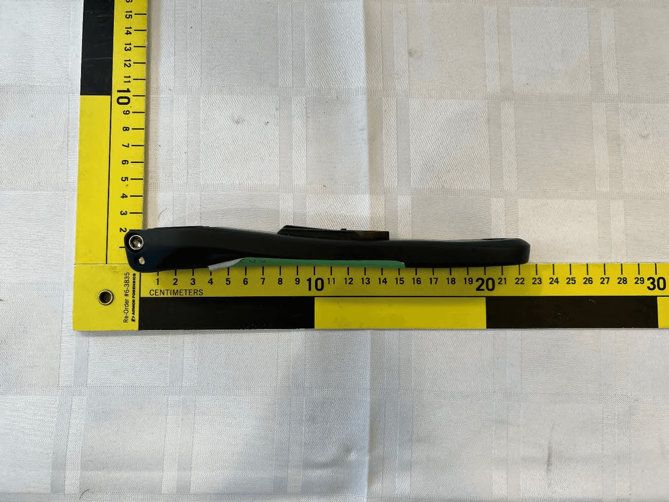
ZZNPM301
Jun 05, 2023Power meter with BLE and ANT+ for bicycle
Equipment Class
DTS - Digital Transmission System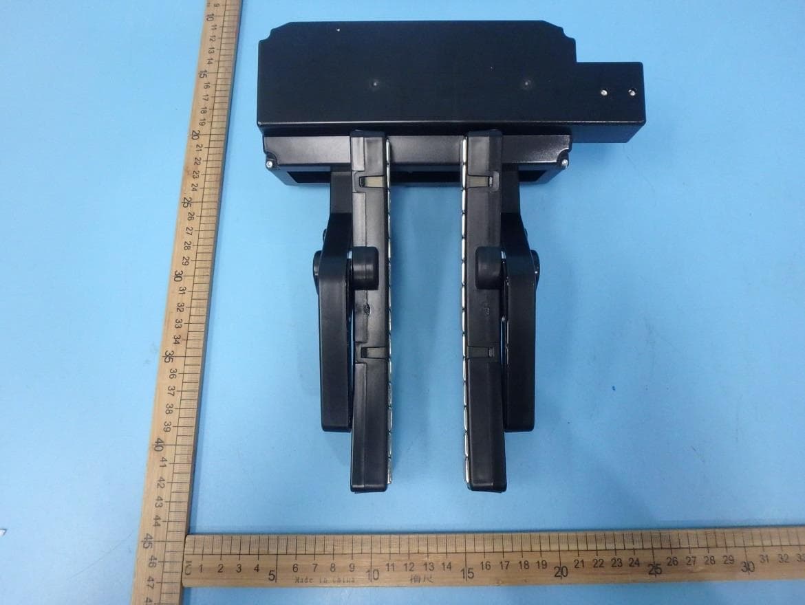
ZZN-ST100
Mar 09, 2020Smart bicycle trainer
Equipment Class
DTS - Digital Transmission System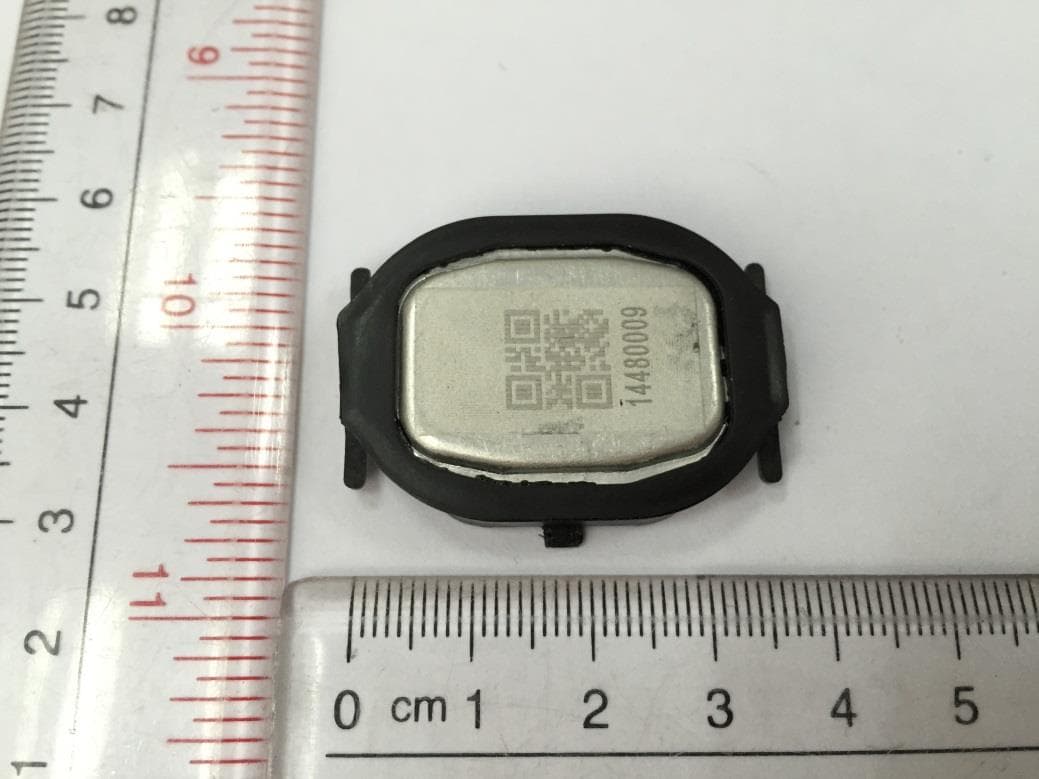
ZZNPM100
May 08, 2015Precision
Equipment Class
DXX - Part 15 Low Power Communication Device Transmitter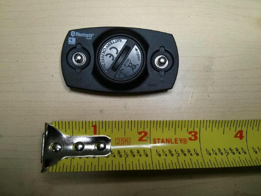
ZZNV100
Feb 10, 2013ZZNV100 ATHLETIC HEART RATE MONITOR ANT AND BTLE
Equipment Class
DXX - Part 15 Low Power Communication Device Transmitter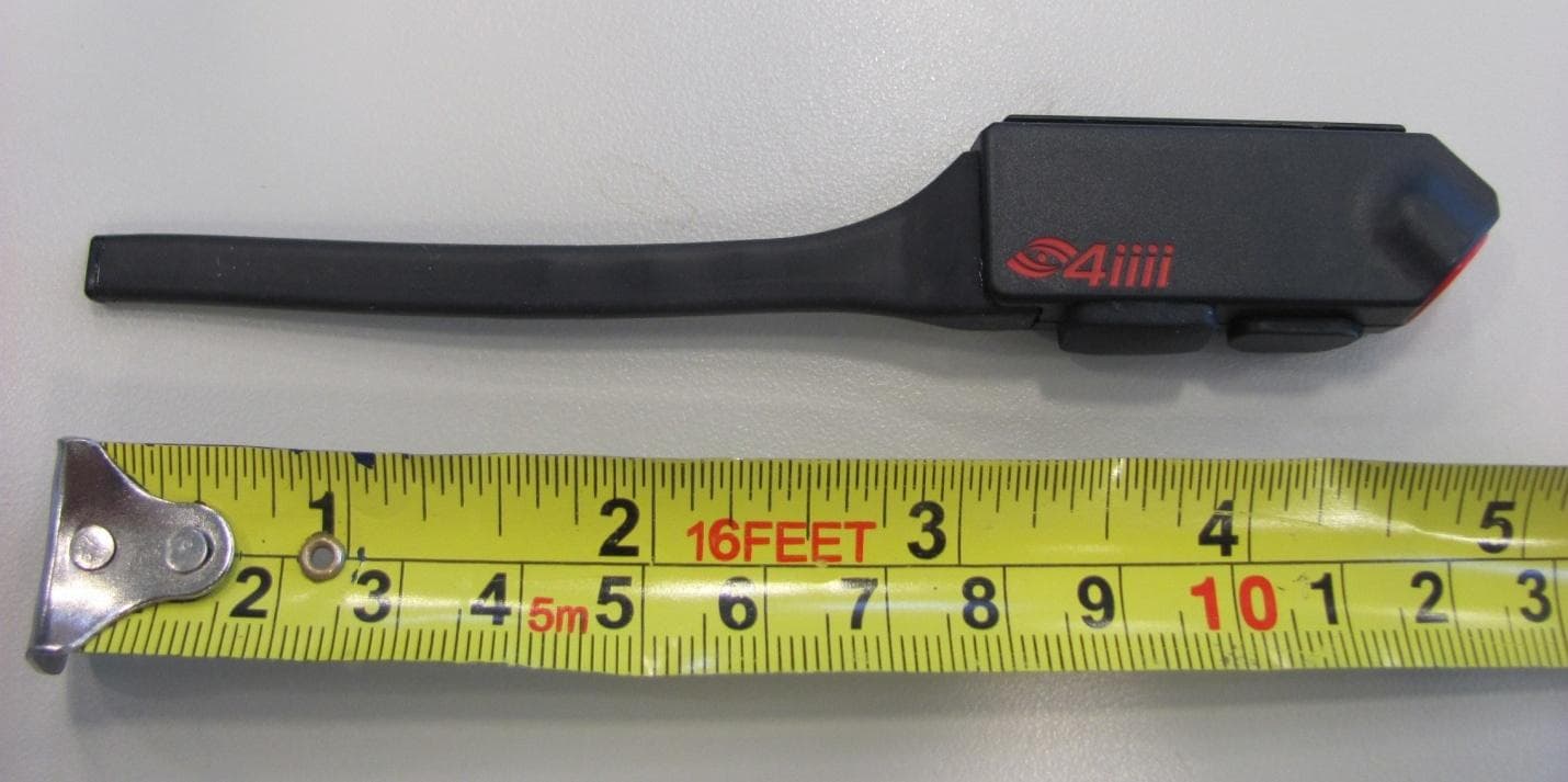
ZZNSP200
Dec 23, 2012ATHLETIC PARAMETER LED DISPLAY
Equipment Class
DXX - Part 15 Low Power Communication Device Transmitter